
My C5 dash has gone nuts and I have every message there is!!!
 05-08-2012, 10:12 PM
#1
Tech Contributor


Thread Starter

Member Since: Dec 1999
Location: Anthony TX
Posts: 32,736
Received 2,180 Likes
on
1,583 Posts
CI 6,7,8,9,11 Vet
St. Jude Donor '08

This post is being constructed to save my fingers and a little time. I have answered this question too many times to count so,, I'm making it something I can add to my File of saved post so that I can add it to any post asking for help when this issues happens as simply as copying the link or the information:
So,, your IPC goes crazy,, your door or doors don't work electrically and your getting NUMEROUS messages,,,, BUT,,,, you can still drive the car.
Some of you wont be able to start the car when the serial data buss goes crazy. That is what happens to my 02 ZO6 when the serial Data Buss get corrupted.
Heres what you need to do to troubleshoot the problem AND FIX IT.
Check the following:
1. Has water entered the passengers compartment? Is your Body Control Module (BCM) big silver box in the Passengers Foot Well behind the toe board wet or damp?
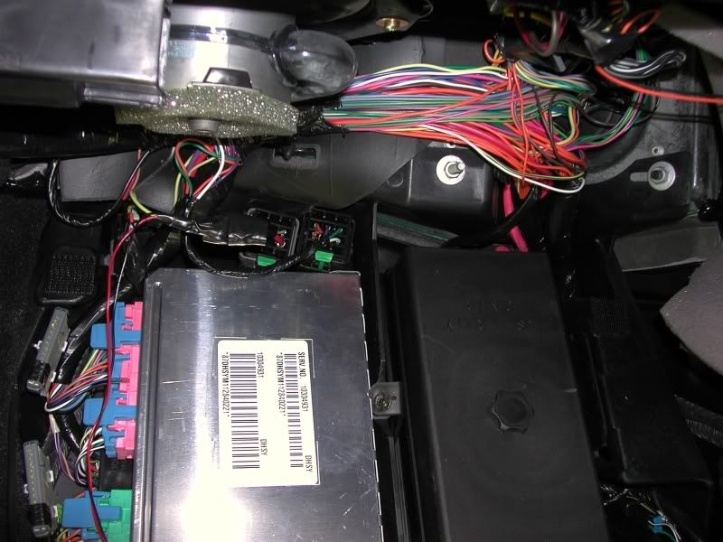
Feel the jute carpet underlayment and see if it is damp or wet. Move the passengers seat fully forward and run your hand up under the carpet and check the area under the seat. If you feel dampness, its very possible that the BCM got wet or damp! NOTE! The BCM DOES NOT LIKE WATER!!!!!!!! It MUST be dry to work properly!!
2. Do you have a Class 2 Serial Data Bus issue? If the data wires that connect each module short or get corrupt, It can cause the IPC to go crazy and display erroneous messages and alerts.
The most common cause of the data buss issues are moisture but, if your carpets and the BCM are DRY,, you could have an electrical issue.
There are THREE COMMON modules that frequently contribute to this issue. They are the: Left Door Control Module (LDCM), Right Door Control Module (RDCM) and the Seat Control Module (SCM)..
To figure out if one of the THREE modules are causing the issue, you can preform an easy procedure!
To the LEFT of the BCM are two thin connectors. They are the Class 2 Serial Data Bus STAR connectors. All the modules and the OBDII ALDL connector are connected together in both of these connectors:
The TOP of both of those thin connectors are a shorting bar that connects all the wires together in that connector.
If you remove the top "shorting bar", you open up (isolate) the modules that terminate in that connector. NOTE! Always examine the male and female pins inside the STAR Connectors when you open them up. There have been damaged connector from the factory.
If you remove the top of the STAR 2 Connector, (the one with FOUR wires in it) you isolate the serial data of the LDCM, RDCM and the SCM.
Once you have that connector disconnected, turn on the ignition switch and see if you clear the INSANITY! Then start the engine, CLEAR ALL THE DTCs and see if you have normal function of all the other modules. When you remove the top of that connector, You WILL have NO COMMS messaged for the three modules listed above. That is NORMAL!
If you regain normal functions,,, one or all three of the disconnected modules are causing the issue.
Start with the left and right door control modules. Another forum member found the cause of this issue so, its NOT my discovery.
For the longest time, it was believed that the wire in the clear sheaf that has exposed conductors caused this issue!!
WRONG!
Its a SPEAKER SHIELD WIRE and has NOTHING to do with the issue!
The real cause of the problem is poor connection/s in the door connectors. Mainly the power connector.
The rubber accordion tube between the doors is a conduit for the door WIRE HARNESS. Disconnect accordion tubes between the door and door frame. They easily pop in and out.
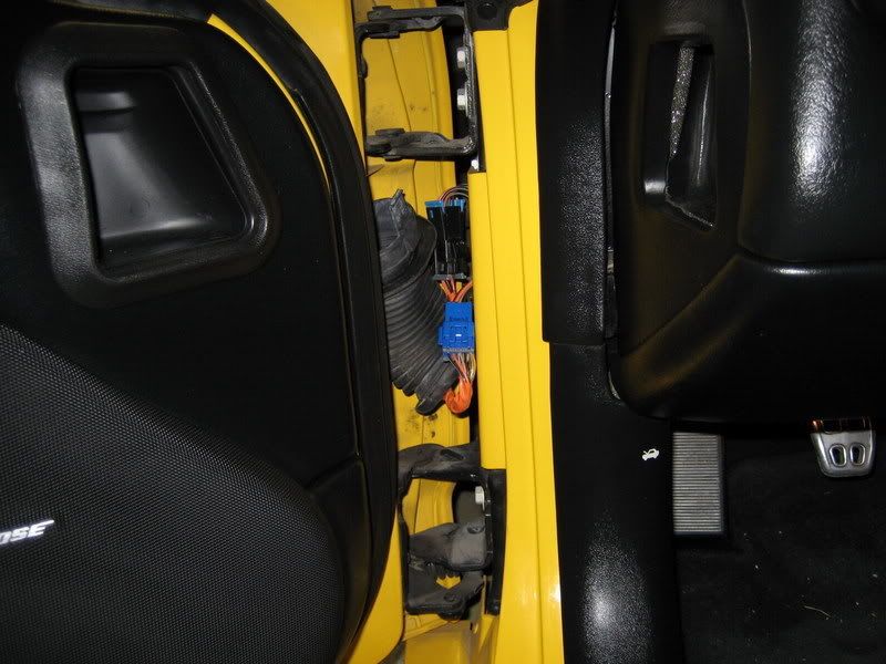
The door connectors live inside the hole in the DOOR FRAME "A" PILLAR. Fish the connectors out of the hole in the door frame. Yes,,, Its Short and will not pull out very far.
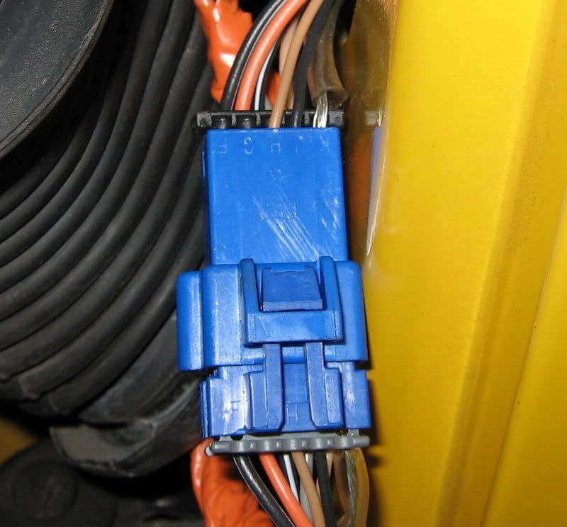
Disconnect the connectors and examine the male and female pins. The FEMALE pins in the connectors are easily damaged by heat and vibration and distort. When they distort, they make a POOR CONNECTION and any vibration can cause the power to that module to turn on and off rapidly. This causes the serial data buss data corruption. My ZO6 brand new purchased by ME from a dealer in 02 had bad pins and it was NEVER disturbed previously!! CRAZY!
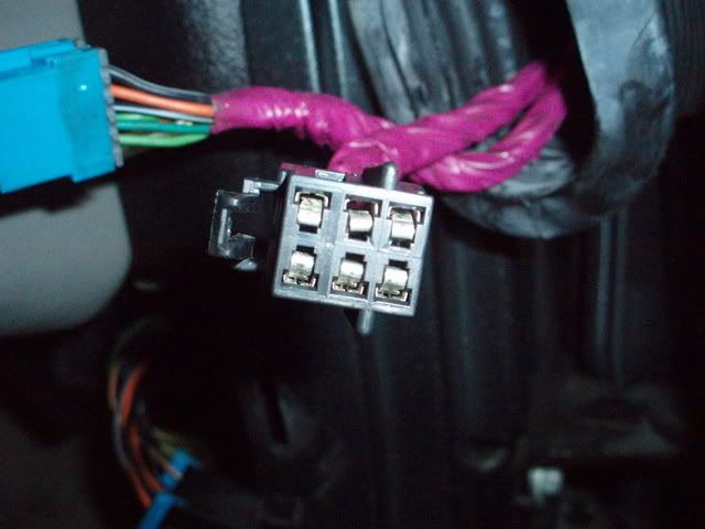
Here is a good example of a power plug with a damaged FEMALE PIN:
The only way to properly test the female pins for proper mechanical contact with the male pin is to insert a proper size male pin into the female pin. Here is a picture of a pin that I use to test female pins:
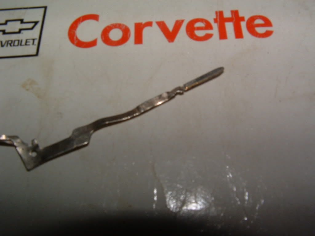
When you insert the pin into the female pin, you should feel resistance inserting and removing it.
To fix the pin properly you should replace it BUT,,, if your careful, you can use a metal pick (I use a dental pick) and bend the metal tong back in place so that it makes positive contact with the male pin.
The seat control module connector under the DRIVERS SEAT sits very LOW and can easily be damaged when the seat moves, Check that connector for damaged wires.
If you have any MOISTURE (read water) under the drivers seat. it will SHORT OUT the SCM serial data wire!
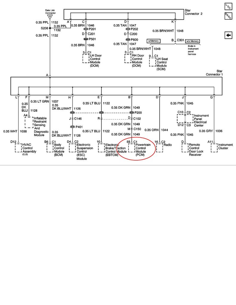
Some stuff to know. There are other problems that can cause serial data buss issues. If all else fails and you can not figure out what module is causing serial data issues... disconnect BOTH CLASS 2 connector tops.
CONNECT the serial wire for the BCM & the PCM (PIN "M" and PIN "B") with a single wire. If the BCM and PCM are working properly the engine will start and run normally.
"U" series DTCs can indicate Module Communications or Power issues. Don't just ignore the U series DTCs
If a module fails to communicate, make SURE that it has proper POWER & GROUNDS
Most of the modules in your car have "TWO" 12 VDC power supplies. One that is called "HOT AT ALL TIMES" That BUS should read full battery voltage all the time! The voltage is used to keep module memory alive and to allow the module to function thru the BCM.
The other 12 VDC power is supplied to the modules when the ignition switch is ON or "HOT IN RUN & START"
The Ignition Switch gets it power from the HOT AT ALL TIMES bus and supplies switch power to the modules and fuel pump.
The IPC Digital Voltage reading in the DIC and the Instrument Cluster ANALOG VOLT METER get their power from the (HOT IN RUN & START) AFTER or thru the ignition switch.
The voltage readings on BOTH of those meters is NOT actual battery voltage. If the electrical contacts inside the IGNITION SWITCH are compromised, the voltage reading that you see will on both of those meters will be LESS than the actual HOT AT ALL TIMES bus voltage readings.
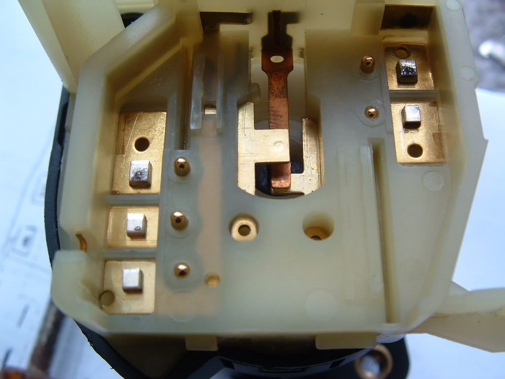
I have seen the output of the ignition switch read as low as 8 VDC because of bad electrical connections inside the ignition switch:
Here is a complete post that explains WHY and what to do to repair the ignition switch problem!
- C5 ignition Switch repair - http://forums.corvetteforum.com/c5-t...ch-repair.html
If you have water issues causing ANY of theses issues, look in the stickies for my leak check post.
Hope this helps someone get their C5 back on the road!


Bill Curlee
So,, your IPC goes crazy,, your door or doors don't work electrically and your getting NUMEROUS messages,,,, BUT,,,, you can still drive the car.
Some of you wont be able to start the car when the serial data buss goes crazy.
That is what happens to my 02 ZO6 when the serial Data Buss get corrupted.Heres what you need to do to troubleshoot the problem AND FIX IT.
Check the following:
1. Has water entered the passengers compartment? Is your Body Control Module (BCM) big silver box in the Passengers Foot Well behind the toe board wet or damp?
Feel the jute carpet underlayment and see if it is damp or wet. Move the passengers seat fully forward and run your hand up under the carpet and check the area under the seat. If you feel dampness, its very possible that the BCM got wet or damp! NOTE! The BCM DOES NOT LIKE WATER!!!!!!!! It MUST be dry to work properly!!
2. Do you have a Class 2 Serial Data Bus issue? If the data wires that connect each module short or get corrupt, It can cause the IPC to go crazy and display erroneous messages and alerts.
The most common cause of the data buss issues are moisture but, if your carpets and the BCM are DRY,, you could have an electrical issue.
There are THREE COMMON modules that frequently contribute to this issue. They are the: Left Door Control Module (LDCM), Right Door Control Module (RDCM) and the Seat Control Module (SCM)..
To figure out if one of the THREE modules are causing the issue, you can preform an easy procedure!
To the LEFT of the BCM are two thin connectors. They are the Class 2 Serial Data Bus STAR connectors. All the modules and the OBDII ALDL connector are connected together in both of these connectors:
The TOP of both of those thin connectors are a shorting bar that connects all the wires together in that connector.
If you remove the top "shorting bar", you open up (isolate) the modules that terminate in that connector. NOTE! Always examine the male and female pins inside the STAR Connectors when you open them up. There have been damaged connector from the factory.
If you remove the top of the STAR 2 Connector, (the one with FOUR wires in it) you isolate the serial data of the LDCM, RDCM and the SCM.
Once you have that connector disconnected, turn on the ignition switch and see if you clear the INSANITY! Then start the engine, CLEAR ALL THE DTCs and see if you have normal function of all the other modules. When you remove the top of that connector, You WILL have NO COMMS messaged for the three modules listed above. That is NORMAL!
If you regain normal functions,,, one or all three of the disconnected modules are causing the issue.
Start with the left and right door control modules. Another forum member found the cause of this issue so, its NOT my discovery.
For the longest time, it was believed that the wire in the clear sheaf that has exposed conductors caused this issue!!
WRONG!
Its a SPEAKER SHIELD WIRE and has NOTHING to do with the issue!
The real cause of the problem is poor connection/s in the door connectors. Mainly the power connector.
The rubber accordion tube between the doors is a conduit for the door WIRE HARNESS. Disconnect accordion tubes between the door and door frame. They easily pop in and out.
The door connectors live inside the hole in the DOOR FRAME "A" PILLAR. Fish the connectors out of the hole in the door frame. Yes,,, Its Short and will not pull out very far.
Disconnect the connectors and examine the male and female pins. The FEMALE pins in the connectors are easily damaged by heat and vibration and distort. When they distort, they make a POOR CONNECTION and any vibration can cause the power to that module to turn on and off rapidly. This causes the serial data buss data corruption. My ZO6 brand new purchased by ME from a dealer in 02 had bad pins and it was NEVER disturbed previously!! CRAZY!
Here is a good example of a power plug with a damaged FEMALE PIN:
The only way to properly test the female pins for proper mechanical contact with the male pin is to insert a proper size male pin into the female pin. Here is a picture of a pin that I use to test female pins:
When you insert the pin into the female pin, you should feel resistance inserting and removing it.
To fix the pin properly you should replace it BUT,,, if your careful, you can use a metal pick (I use a dental pick) and bend the metal tong back in place so that it makes positive contact with the male pin.
The seat control module connector under the DRIVERS SEAT sits very LOW and can easily be damaged when the seat moves, Check that connector for damaged wires.
If you have any MOISTURE (read water) under the drivers seat. it will SHORT OUT the SCM serial data wire!
Some stuff to know. There are other problems that can cause serial data buss issues. If all else fails and you can not figure out what module is causing serial data issues... disconnect BOTH CLASS 2 connector tops.
CONNECT the serial wire for the BCM & the PCM (PIN "M" and PIN "B") with a single wire. If the BCM and PCM are working properly the engine will start and run normally.
"U" series DTCs can indicate Module Communications or Power issues. Don't just ignore the U series DTCs
If a module fails to communicate, make SURE that it has proper POWER & GROUNDS
Most of the modules in your car have "TWO" 12 VDC power supplies. One that is called "HOT AT ALL TIMES" That BUS should read full battery voltage all the time! The voltage is used to keep module memory alive and to allow the module to function thru the BCM.
The other 12 VDC power is supplied to the modules when the ignition switch is ON or "HOT IN RUN & START"
The Ignition Switch gets it power from the HOT AT ALL TIMES bus and supplies switch power to the modules and fuel pump.
The IPC Digital Voltage reading in the DIC and the Instrument Cluster ANALOG VOLT METER get their power from the (HOT IN RUN & START) AFTER or thru the ignition switch.
The voltage readings on BOTH of those meters is NOT actual battery voltage. If the electrical contacts inside the IGNITION SWITCH are compromised, the voltage reading that you see will on both of those meters will be LESS than the actual HOT AT ALL TIMES bus voltage readings.
I have seen the output of the ignition switch read as low as 8 VDC because of bad electrical connections inside the ignition switch:
Here is a complete post that explains WHY and what to do to repair the ignition switch problem!
- C5 ignition Switch repair - http://forums.corvetteforum.com/c5-t...ch-repair.html
If you have water issues causing ANY of theses issues, look in the stickies for my leak check post.
Hope this helps someone get their C5 back on the road!
Bill Curlee
Last edited by Bill Curlee; 07-14-2015 at 01:42 PM.

The following 13 users liked this post by Bill Curlee:
Alley Oop (10-07-2021),
blackmachdown (07-15-2017),
BmoreRnsDeep (01-08-2022),
C5inator (09-18-2015),
El original (07-18-2017),
and 8 others liked this post.


 05-09-2012, 09:05 AM
#4
Tech Contributor
Bill - you are truly an asset to the C5 community. While there are many others with the aptitude and knowledge to diagnose and fix, you are one of the few that also has the ability/desire to document and teach. Thank you.

 05-09-2012, 05:47 PM
#7
Tech Contributor
Thread Starter
Member Since: Dec 1999
Location: Anthony TX
Posts: 32,736
Received 2,180 Likes
on
1,583 Posts
CI 6,7,8,9,11 Vet
St. Jude Donor '08
Thanks Bud!! Im going to save your picture if you dont mind. Its PURDY!
Bill
Bill
 05-09-2012, 09:09 PM
#9
Race Director

I went through this over the winter. I checked and cleaned oll the ground on the block, driver's side head, front frame rails. I also pulled the accordian connectors as shown here. They appeared straight and clean but I cleaned them up more.
Thanks to Bill and Lucky, it's all good now. Some of this stuff should almost be preventive maintenance.
Thanks to Bill and Lucky, it's all good now. Some of this stuff should almost be preventive maintenance.
09-30-2012, 05:41 PM
#11
Tech Contributor
Thread Starter
Member Since: Dec 1999
Location: Anthony TX
Posts: 32,736
Received 2,180 Likes
on
1,583 Posts
CI 6,7,8,9,11 Vet
St. Jude Donor '08
TTT for more people to view.
Bill
Bill

 01-12-2013, 09:20 PM
#13
Tech Contributor
Thread Starter
Member Since: Dec 1999
Location: Anthony TX
Posts: 32,736
Received 2,180 Likes
on
1,583 Posts
CI 6,7,8,9,11 Vet
St. Jude Donor '08
When your Body Control Module gets wet and stays wet for a long period of time,, this is what happens to the circuit board inside the big silver box.
Its a white powdery residue that can and will cause BCM electrical issues.
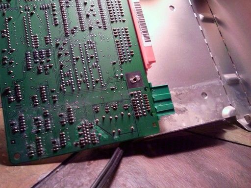
If you have this on the circuit board, remove as much as you can with a soft bristle nylon bush and then add some alcohol to flush the rest off.
NOTE!! The Circuit Board is Electrostatic Discharge (ESD) sensitive. DO NOT touch the board if your are not properly grounded. Static electricity will damage the board.
BC
Its a white powdery residue that can and will cause BCM electrical issues.
If you have this on the circuit board, remove as much as you can with a soft bristle nylon bush and then add some alcohol to flush the rest off.
NOTE!! The Circuit Board is Electrostatic Discharge (ESD) sensitive. DO NOT touch the board if your are not properly grounded. Static electricity will damage the board.
BC
 07-04-2013, 01:52 PM
#15
Tech Contributor
Thread Starter
Member Since: Dec 1999
Location: Anthony TX
Posts: 32,736
Received 2,180 Likes
on
1,583 Posts
CI 6,7,8,9,11 Vet
St. Jude Donor '08
You need to remove the IPC and dig into it. You either have a poor connection on one of the circuit boards OR there are cold solder joints on some of the surface mount resistors.
If you cant do electronic work/troubleshooting, find a TV repair shop that is willing to take on the work. Its simple if you have the tools and knowledge and know what to look for.
Here are a few post that you can review. The HVAC Control module is a PRIME EXAMPLE of what happens and what is needed to fix it:
- C5 HVAC Display repair: http://forums.corvetteforum.com/c5-t...splay-fix.html
I also included some WHATS INSIDE MY IPC post:
- C5 Gage Cluster disassembly - http://forums.corvetteforum.com/c5-t...post1570380674
- C5 Gage Cluster Post - http://forums.corvetteforum.com/c5-t...post1570380878
Last edited by Bill Curlee; 07-04-2013 at 02:43 PM.
The following users liked this post:
Rick369 (05-19-2016)
03-20-2014, 12:09 AM
#16
Racer

Bill
Just wanted to say THANK YOU.
I had these problems last week with my 98 and was kind of freaking out.
I believe that I've narrowed it down to the wires in the door accordion thanks to your post.
I appreciate you helping us out here on CF.
Thank you again.
If you come to Cali I'll buy you a drink of your choice
 01-25-2015, 11:52 AM
#18
Heel & Toe

Member Since: Jan 2015
Posts: 21
Likes: 0
Received 0 Likes
on
0 Posts
This post is being constructed to save my fingers and a little time. I have answered this question too many times to count so,, I'm making it something I can add to my File of saved post so that I can add it to any post asking for help when this issues happens as simply as copying the link or the information:
So,, your IPC goes crazy,, your door or doors don't work electrically and your getting NUMEROUS messages,,,, BUT,,,, you can still drive the car.
Some of you wont be able to start the car when the serial data buss goes crazy.
Heres what you need to do to troubleshoot the problem AND FIX IT.
Check the following:
1. Has water entered the passengers compartment? Is your Body Control Module (BCM) big silver box in the Passengers Foot Well behind the toe board wet or damp?
Feel the jute carpet underlayment and see if it is damp or wet. Move the passengers seat fully forward and run your hand up under the carpet and check the area under the seat. If you feel dampness, its very possible that the BCM got wet or damp! NOTE! The BCM DOES NOT LIKE WATER!!!!!!!! It MUST be dry to work properly!!
2. Do you have a Class 2 Serial Data Bus issue? If the data wires that connect each module short or get corrupt, It can cause the IPC to go crazy and display erroneous messages and alerts.
The most common cause of the data buss issues are moisture but, if your carpets and the BCM are DRY,, you could have an electrical issue.
There are THREE COMMON modules that frequently contribute to this issue. They are the: Left Door Control Module (LDCM), Right Door Control Module (RDCM) and the Seat Control Module (SCM)..
To figure out if one of the THREE modules are causing the issue, you can preform an easy procedure!
To the LEFT of the BCM are two thin connectors. They are the Class 2 Serial Data Bus STAR connectors. All the modules and the OBDII ALDL connector are connected together in both of these connectors:
The TOP of both of those connector are a shorting bar that connect all the wires together in that connector.
If you remove the top shorting bar, you open up (isolate) the modules that terminate in that connector.
If you remove the top of the STAR 2 Connector, (the one with FOUR wires in it) you isolate the serial data of the LDCM, RDCM and the SCM.
Once you have that connector disconnected, turn on the ignition switch and see if you clear the INSANITY! Then start the engine, CLEAR ALL THE DTCs and see if you have normal function of all the other modules.
If you regain normal functions,,, one or all three of the disconnected modules are causing the issue.
Start with the left and right door control modules. Another forum member found the cause of this issue so, its NOT my discovery.
For the longest time, it was believed that the wire in the clear sheaf that has exposed conductors caused this issue!!
WRONG!
Its a SPEAKER SHIELD WIRE and has NOTHING to do with the issue!
The real cause of the problem is poor connection/s in the door connectors. Mainly the power connector.
The rubber accordion tube between the doors is a conduit for the door WIRE HARNESS. Disconnect accordion tubes between the door and door frame. They easily pop in and out.
The door connectors live inside the hole in the DOOR FRAME "A" PILLAR. Fish the connectors out of the hole in the door frame.
Disconnect the connectors and examine the male and female pins. The FEMALE pins in the connectors are easily damaged by heat and vibration and distort. When they distort, they make a POOR CONNECTION and any vibration can cause the power to that module to turn on and off rapidly. This causes the serial data buss data corruption.
Here is a good example of a power plug with a damaged FEMALE PIN:
The only way to properly test the female pins for proper mechanical contact with the male pin is to insert a proper size male pin into the female pin. Here is a picture of a pin that I use to test female pins:
When you insert the pin into the female pin, you should feel resistance inserting and removing it.
To fix the pin properly you should replace it BUT,,, if your careful, you can use a metal pick (I use a dental pick) and bend the metal tong back in place so that it makes positive contact with the male pin.
The seat control module connector under the DRIVERS SEAT sits very LOW and can easily be damaged when the seat moves, Check that connector for damaged wires.
If you have any MOISTURE (read water) under the drivers seat. it will SHORT OUT the SCM serial data wire!
Some stuff to know. There are other problems that can cause serial data buss issues. If all else fails and you can not figure out what module is causing serial data issues... disconnect BOTH CLASS 2 connector tops.
CONNECT the serial wire for the BCM & the PCM (PIN "M" and PIN "B") with a single wire. If the BCM and PCM are working properly the engine will start and run normally.
"U" series DTCs can indicate Module Communications or Power issues. Don't just ignore the U series DTCs
If a module fails to communicate, make SURE that it has proper POWER & GROUNDS
Most of the modules in your car have "TWO" 12 VDC power supplies. One that is called "HOT AT ALL TIMES" That BUS should read full battery voltage all the time! The voltage is used to keep module memory alive and to allow the module to function thru the BCM.
The other 12 VDC power is supplied to the modules when the ignition switch is ON or "HOT IN RUN & START"
The Ignition Switch gets it power from the HOT AT ALL TIMES bus and supplies switch power to the modules and fuel pump.
The IPC Digital Voltage reading in the DIC and the Instrument Cluster ANALOG VOLT METER get their power from the (HOT IN RUN & START) AFTER or thru the ignition switch.
The voltage readings on BOTH of those meters is NOT actual battery voltage. If the electrical contacts inside the IGNITION SWITCH are compromised, the voltage reading that you see will on both of those meters will be LESS than the actual HOT AT ALL TIMES bus voltage readings.
I have seen the output of the ignition switch read as low as 8 VDC because of bad electrical connections inside the ignition switch:
Here is a complete post that explains WHY and what to do to repair the ignition switch problem!
- C5 ignition Switch repair - http://forums.corvetteforum.com/c5-t...ch-repair.html
If you have water issues causing ANY of theses issues, look in the stickies for my leak check post.
Hope this helps someone get their C5 back on the road!
Bill Curlee
After I installed the old module yesterday and it worked door open but not with the door closed I knew I had to check the connector in the pictures. I was difficult from me to understand that being the problem but when I disconnected the black plug I became a believer. 3 of my female connectors looked like the picture including the center one described in the picture
I used a piece of a metal coat hanger from the backside of the pin to reduce the gap. No dental pick on hand but you could also use an icepick mine had a broken point and would not fit in the pin, maybe that was a good thing.
I had found a copy of this post when we first started having this problem and before I purchased the used module but didn't understand how a connection that is never touched in the 13 years we've had the car could be the problem and the used module was cheap and easy fix. The post I found steered you to the clear coated silver wire so I'm glad that has been updated in this new version.
I installed the original module replaced in 04 glad I kept it and everything works under all conditions so far. Sometimes the first reply to a post is best.
One more time Thanks Again to All that responded

Next up hazard flasher install
 07-13-2015, 08:50 PM
#19
Thank You and thank everyone that responded to my plea for help. I was almost ready to replace the module again but wanted to check the connections before I did that. I checked for water intrusion but everything was dry but I was pretty sure what I had was an electrical problem.
After I installed the old module yesterday and it worked door open but not with the door closed I knew I had to check the connector in the pictures. I was difficult from me to understand that being the problem but when I disconnected the black plug I became a believer. 3 of my female connectors looked like the picture including the center one described in the picture
I used a piece of a metal coat hanger from the backside of the pin to reduce the gap. No dental pick on hand but you could also use an icepick mine had a broken point and would not fit in the pin, maybe that was a good thing.
I had found a copy of this post when we first started having this problem and before I purchased the used module but didn't understand how a connection that is never touched in the 13 years we've had the car could be the problem and the used module was cheap and easy fix. The post I found steered you to the clear coated silver wire so I'm glad that has been updated in this new version.
I installed the original module replaced in 04 glad I kept it and everything works under all conditions so far. Sometimes the first reply to a post is best.
One more time Thanks Again to All that responded
Next up hazard flasher install
07-14-2015, 01:28 PM
#20
Tech Contributor
Thread Starter
Member Since: Dec 1999
Location: Anthony TX
Posts: 32,736
Received 2,180 Likes
on
1,583 Posts
CI 6,7,8,9,11 Vet
St. Jude Donor '08

Ive had some luck with NAPA.
Our local Advance Auto have some pins.
You can always call Gene Culley and see if he has pins and pigtails..
Bill