
Fuel level sending unit
 07-06-2013, 03:13 PM
#1


Can someone please post a picture or clearly explain how to be sure that I have correctly wired my new passenger side fuel sending unit?
I'm getting two codes 0461H and 1432 HC. I replaced the passenger fuel sender, but this did not fix the problem. I was confused by the fact that the replacement fuel sending units have 2 wires, and the original 1997 fuel sending units have 3. Furthermore the colors for the wires were not the same on both sides of the connector.
If you know how to correctly wire the fuel sending unit on the passenger side, please enlighten me.
Thanks,
Chris
 07-06-2013, 04:05 PM
#2
Alright, so here's what it looks like:
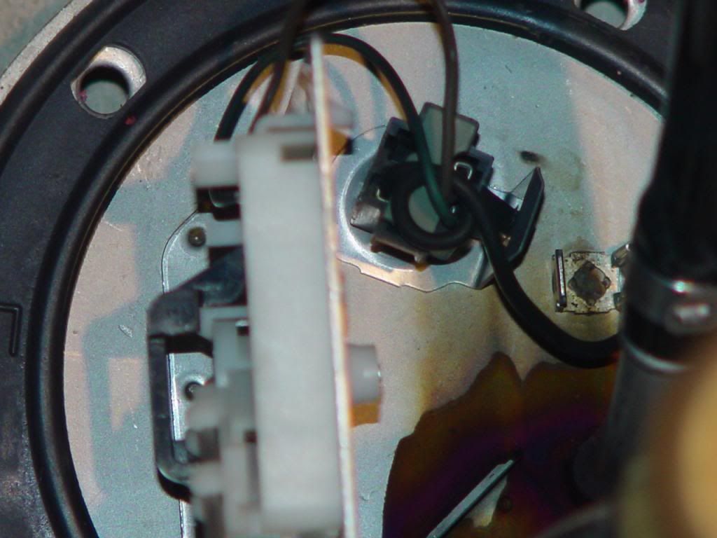
First, here's the sending unit. This picture is looking downward from the passenger side with the camera in the wheel well looking inward at the fuel tank. The white piece is the sender, and you can see that it's hanging by the float arm. Note the blue and grey wire. The old sender had 3 wires, this sender has only these 2.

This one is from under the car, upside down, looking upwards, and a little outwards, back towards the wheel well. For lack of a better term, the black thing is the pin receiver, and you can see the blue and grey wires, as well as a black wire that was already there.

For reference, that orange thing up there is the connector that I had to unplug the "pin receiver" from to get access to the wires. When it's plugged in, I currently have the black wire on the top right side, the blue wire on the top left, and the grey wire on the bottom left. Maybe Gene Culley just sent me the wrong part twice? Shouldn't I still have 3 wires? If only two, then should they be plugged in a different way?

Finally, this picture gives you a better idea of the positioning of the wires. Again, the black on the top right, and I currently have the blue on the top left, and the grey on the bottom left. The positioning of everything is looking towards connector from the fuel tank. So the black wire is actually closest to the driver's side, the blue and grey wires are closest to the passenger side of the car.

Someone with teh knowledge, please help.
First, here's the sending unit. This picture is looking downward from the passenger side with the camera in the wheel well looking inward at the fuel tank. The white piece is the sender, and you can see that it's hanging by the float arm. Note the blue and grey wire. The old sender had 3 wires, this sender has only these 2.
This one is from under the car, upside down, looking upwards, and a little outwards, back towards the wheel well. For lack of a better term, the black thing is the pin receiver, and you can see the blue and grey wires, as well as a black wire that was already there.
For reference, that orange thing up there is the connector that I had to unplug the "pin receiver" from to get access to the wires. When it's plugged in, I currently have the black wire on the top right side, the blue wire on the top left, and the grey wire on the bottom left. Maybe Gene Culley just sent me the wrong part twice? Shouldn't I still have 3 wires? If only two, then should they be plugged in a different way?
Finally, this picture gives you a better idea of the positioning of the wires. Again, the black on the top right, and I currently have the blue on the top left, and the grey on the bottom left. The positioning of everything is looking towards connector from the fuel tank. So the black wire is actually closest to the driver's side, the blue and grey wires are closest to the passenger side of the car.
Someone with teh knowledge, please help.
Last edited by Chris Arnold; 07-06-2013 at 07:27 PM.
07-08-2013, 08:08 AM
#4
Since I seem to be blazing down this path for the first time in Corvette history  , for posterity's sake here's are the relevant wiring diagrams from a helpful member of another forum that might help lead to a solution to this or other problems:
So, this wiring diagram at least confirms that the later cars had 2-wire fuel senders. It still leaves me with some unanswered questions.
Forgive me for my lack of electrical know-how, but I can't figure out how to use the diagram to tell me the right way to wire this thing. I can see that the terminals on the '97 are marked A, B, C, & D, and that they are marked on B, C, & D, on the '99. I can also see that on the '99 the grey wire goes to terminal B and the blue wire goes to terminal C, but I can't figure out which terminals are which on the actual parts. I'll take another look to see if I missed some markings on one of them. Any ideas?
, for posterity's sake here's are the relevant wiring diagrams from a helpful member of another forum that might help lead to a solution to this or other problems: So, this wiring diagram at least confirms that the later cars had 2-wire fuel senders. It still leaves me with some unanswered questions.
Forgive me for my lack of electrical know-how, but I can't figure out how to use the diagram to tell me the right way to wire this thing. I can see that the terminals on the '97 are marked A, B, C, & D, and that they are marked on B, C, & D, on the '99. I can also see that on the '99 the grey wire goes to terminal B and the blue wire goes to terminal C, but I can't figure out which terminals are which on the actual parts. I'll take another look to see if I missed some markings on one of them. Any ideas?
07-08-2013, 09:55 AM
#5
Found another piece to the puzzle:


B and D are confusing, since the orange connector shows that B on the black pin-receiver is D as it exits, but after looking at it and referring back to the wiring diagram, I think it's wired correctly. You can see that the wiring diagram references A, B, C, and D. The black pin receiver does not reference a terminal A, but rather a terminal E. The output from the orange connector shows that terminal E becomes output "A". In any case, A/E isn't used at all with the new sending unit. I do not believe when I first changed the wires that I ever pulled the black wire out of the black pin receiver. So, assuming it was ever wired correctly, it, the black wire, should be terminal "B" in the black pin-receiver, and output "D" from the orange connector.
It's actually bad news, because I was really hoping that incorrect wiring was causing all of my problems. So, any thoughts? Am I right about the wiring being correct? Does it turn out that I actually do need a 3-wire sending unit? What else would lead to a faulty fuel gauge and codes 1432, and 0461?
Last edited by Chris Arnold; 07-10-2013 at 06:56 AM.
07-08-2013, 10:56 AM
#6
Melting Slicks


Did you replace the entire sending unit or just the fuel level sensor? What part number did you order and receive?
There appears to have been an upgraded card on the fuel sending unit for the fuel level sensor. I'm guessing by the photos you're just replacing the level sensor. I don't know if you can just replace the fuel level sensor portion and have it all work the same as before. (If I'm reading the diagram correctly, they just eliminated a redundant ground which should work for your application)
What color are your wires to the yellow connector? Make sure the wires between the yellow connector and the black connector are good.
Last edited by 3sACROWD; 07-08-2013 at 11:07 AM.
07-08-2013, 12:18 PM
#7
Thanks for the interest. The black "pin-receiver," as I've been calling it, connect directly to the orange connector. There are not additional wires. The three wires to the pin-receiver, as you probably already understand, are blue, grey, and black. The black pin-receiver then connects onto the orange connector. In the second picture, you can even see an edge that juts out from the black pin-receiver and the metal catch that locks it into the orange connector.
As far as the other question, I don't really understand it. To me the sending unit and the fuel level sensor are the same thing. At GMpartshouse.com it's referred to as the "10333749 - FUEL GAUGE SENDING UNIT Corvette"
As far as the parts number, Gene Culley at GM parts house sent me part # 10333749, which is actually the driver's side, but gene told me it's the same sending unit on both sides. You'll just end up with the wrong strainer replacement. Of course, mine is still not working. So, I would be careful following in my footsteps until I've worked everything out. Here's the link to the part: http://store.gmpartshouse.com/parts/...&siteid=214638
Last edited by Chris Arnold; 07-08-2013 at 12:20 PM.
07-08-2013, 05:47 PM
#8
Melting Slicks
OK. We're dealing with symantics and I now know what you're calling each item.
I have an 03Z so I'm not sure I'm going to be of assistance by using my set-up for comparison. When I look at my sending unit and compare it to yours, the wires are "flip-flopped" in the black connector. My black wire is in the "D" position, my blue wire is in the "B" position, and the grey wire is in the "E" position. (nothing in the "C" position) The black wire is then connected to one of the "tangs" on the back of the pump assembly plate. (my wires appear to be dk green and brown but I think that is the staining from the gas. If I scrape at the coating, it appears more blue and gray)
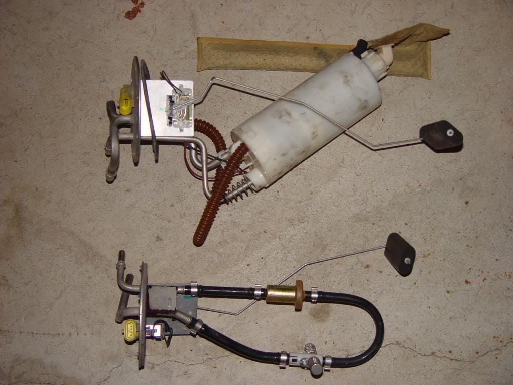
Upper assembly is left tank; lower assembly is right tank.
Do you have a picture of the old sending unit for comparison?
I have an 03Z so I'm not sure I'm going to be of assistance by using my set-up for comparison. When I look at my sending unit and compare it to yours, the wires are "flip-flopped" in the black connector. My black wire is in the "D" position, my blue wire is in the "B" position, and the grey wire is in the "E" position. (nothing in the "C" position) The black wire is then connected to one of the "tangs" on the back of the pump assembly plate. (my wires appear to be dk green and brown but I think that is the staining from the gas. If I scrape at the coating, it appears more blue and gray)
Upper assembly is left tank; lower assembly is right tank.
Do you have a picture of the old sending unit for comparison?
Last edited by 3sACROWD; 07-08-2013 at 05:55 PM.
07-08-2013, 07:26 PM
#10
Would really like to see a wiring diagram specific to your car. I'm feeling a bit desperate to try something else, but the last thing I want to do is pull the ground off of the fuel tank hat and cause a dangerous situation.
Your fuel hat is definitely different, and it's likely that your PCM pin-out differs, as well. If there's anything for sure about the above two wiring diagrams it's that there is a blue wire attached to the C terminal, which is the letter for the terminal on the black connector and the output from the orange/yellow connector. I'm also 99% sure that I never pulled the black wire from the fitting. So it should be as it came from the factory in black-connector terminal B, and orange connector output D. That leaves 2 spots for the grey wire, and unfortunately neither of them worked.
I'm not discounting the possibility that the above wiring diagrams are simply wrong. However, if they are right, then it seems as though my problem lies in the wiring, at the PCM, or in the firmware.
07-08-2013, 08:05 PM
#11
So, I took a multimeter to the new sending unit, and it worked fine. I also tested the orange connector for continuity between the pins in the tank and the ones on the outside of it. Everything checked out fine. I got a really bright idea, that since the wiring diagram shows the variable resistor on terminal A in the 97, but on terminal B in the 99 diagrams, maybe the grey wire should be connected to Terminal A. But, that didn't work either. One thing I was able to confirm is that the driver's side fuel sender is working fine. With the driver's fuel sender at the top, and the codes cleared, the gauge shows almost a half-tank. With its float arm at the bottom, the gauge shows empty. I just can't get any response from the passenger side sender to the gauge.
Is there a way to check the wiring harness' connector? Can I jumper terminal B to terminal C to test the body-side circuit? i.e. shouldn't that change the fuel gauge?
I really don't know what to do next.
Is there a way to check the wiring harness' connector? Can I jumper terminal B to terminal C to test the body-side circuit? i.e. shouldn't that change the fuel gauge?
I really don't know what to do next.
07-08-2013, 08:26 PM
#12
Melting Slicks
Member Since: Nov 1999
Location: MI
Posts: 2,073
Received 556 Likes
on
263 Posts
Cruise-In VI Veteran

Hello, I think I see what�s going on here�.
When I review the manual, there is no procedure to replace just the sender, there is a procedure to replace the assembly and when troubleshooting a 1432 code, the path can lead to replacing the assembly. I believe the schematics do not show the wiring inside the tank, sender wiring to the sender assy or the wires from the tank to the yellow (PED) plug on top of the sender assy, (the schematics show wiring FROM this yellow (PED) plug on top of the sender assy to the cars various systems. If you can confirm the wire colors on the plug the connects to this yellow (PED) plug on the (car side and not inside the fuel tank) this would confirm my info
Kevin
07-08-2013, 08:30 PM
#13
Melting Slicks
Member Since: Nov 1999
Location: MI
Posts: 2,073
Received 556 Likes
on
263 Posts
Cruise-In VI Veteran
1997 Vette DTC P1432 Fuel Level Sensor 2 Circuit Low Voltage
Circuit Description
The Fuel Level sensor 2, mounted in the rear side of the right fuel tank, measures fuel level changes within the right fuel tank. The Fuel Level sensor 2 has a 5.0 volt reference circuit, a ground, and a signal circuit.
When the fuel level is low the sensor output voltage is high. When the fuel level is high the sensor output voltage is low.
The PCM uses inputs from the Fuel Level sensor 1 and the Fuel Level sensor 2 in order to calculate the total fuel remaining in both fuel tanks. The system sends this information via the serial data to the BCM. This information displays on the fuel gauge.
When the PCM senses a signal voltage lower than the normal operating range of the sensor, this DTC sets.
Conditions for Setting the DTC
� The Fuel Level sensor voltage is below 0.39 volts.
� The above condition present for greater than 50 seconds.
Action Taken When the DTC Sets
� The powertrain control module (PCM) stores the DTC information into memory when the diagnostic runs and fails.
� The malfunction indicator lamp (MIL) will not illuminate.
� The PCM records the operating conditions at the time the diagnostic fails. The PCM stores this information in the Failure Records.
Conditions for Clearing the DTC
� A last test failed, or current DTC, clears when the diagnostic runs and does not fail.
� A history DTC will clear after 40 consecutive warm-up cycles, if no failures are reported by this or any other non-emission related diagnostic.
� Use a scan tool in order to clear the DTC.
Diagnostic Aids
The following occurs with this DTC set:
� The vehicle fuel gauge displays empty.
� The Check Gauge lamp illuminates.
� The Driver Information Center displays a message.
Using the Freeze Frame and/or Failure Records data may aid in locating an intermittent condition. If you cannot duplicate the DTC, the information included in the Freeze Frame and/or Failure Records data can help determine how many miles since the DTC set. The Fail Counter and Pass Counter can also help determine how many ignition cycles the diagnostic reported a pass and/or a fail. Operate vehicle within the same freeze frame conditions (RPM, load, vehicle speed, temperature etc.) that you observed. This will isolate when the DTC failed. For an intermittent condition, refer to Symptoms .
Test Description
The numbers below refer to the step numbers on the diagnostic table.
This step determines if the fault is present.
Step
2
Action
Value(s)
Yes
No
1
Did you perform the On-Board Diagnostic (OBD) System Check?
--
Go to Step 2
Go to Powertrain On Board Diagnostic (OBD) System Check
2
Install the scan tool.
Idle the engine at the normal operating temperature.
Monitor Failed This Ignition under DTC Status for DTC P1635 using the scan tool
Did DTC P1635 Fail This Ignition cycle?
--
Go to DTC P1635 5 Volt Reference 1 Circuit
Go to Step 3
3
Install the scan tool.
Turn ON the ignition leaving the engine OFF.
Monitor the Fuel Level Sensor Right Tank parameter using the scan tool.
Is the fuel level sensor right tank voltage below the specified value?
0.39V
Go to Step 5
Go to Step 4
4
Turn ON the ignition leaving the engine OFF.
Review the Freeze Frame and/or Failure Records data for this DTC and observe the parameters.
Turn the ignition OFF for 15 seconds.
Start the engine.
Operate the vehicle within the conditions required for this diagnostic to run, and as close to the conditions recorded in Freeze Frame/Failure Records as possible. Special operating conditions that need to be met before the PCM will run this diagnostic, where applicable, are listed in Conditions for Setting the DTC.
Select the Diagnostic Trouble Code (DTC) option and the Clear DTC Information option, then enter the DTC number using the scan tool.
Does the scan tool indicate that this diagnostic failed this ignition?
--
Go to Step 5
Refer to Diagnostic Aids
5
Disconnect the right tank fuel level sensor at the right fuel tank.
Jumper the right tank fuel level sensor 5.0 volt reference circuit and the signal circuit together.
Monitor the Fuel Level Sensor Right Tank parameter using the scan tool.
Is the Fuel Level Sensor Right Tank at the specified value?
5.0V
Go to Step 11
Go to Step 6
6
Connect a test lamp J 35616-200 between B+ and the fuel level sensor right tank signal circuit at the fuel level sensor right tank connector.
Monitor the Fuel Level Sensor Right Tank parameter using the scan tool.
Is the Fuel Level Sensor Right Tank at the specified value?
5.0V
Go to Step 7
Go to Step 9
7
Turn OFF the ignition.
Disconnect the PCM connector located on the same side as the manufacturer's logo. Refer to Powertrain Control Module/Throttle Actuator Control Module Replacement .
Check the right tank fuel level sensor 5.0 volt circuit for an open or a short to ground , repair it as necessary. Refer to Body and Accessories/Wiring Systems .
Was the 5.0 volt reference circuit open or shorted to ground?
--
Go to Step 14
Go to Step 8
8
Check the right tank fuel level sensor 5.0 volt circuit for a poor connection at the PCM and replace the terminal if necessary. Refer to Body and Accessories/Wiring Systems .
Did the terminal require replacement?
--
Go to Step 14
Go to Step 12
9
Turn OFF the ignition.
Disconnect the PCM connector located on the same side as the manufacturer's logo. Refer to Powertrain Control Module/Throttle Actuator Control Module Replacement .
Check the right tank fuel level sensor signal circuit for the following:
� Open circuit.
� Short to ground.
� Short to the sensor ground circuit.
If the right tank fuel level sensor signal circuit is open or shorted to ground, repair it as necessary. Refer to Body and Accessories/Wiring Systems .
Did the terminal require replacement?
--
Go to Step 14
Go to Step 10
10
Check the right tank fuel level sensor signal circuit for a poor connection at the PCM and replace the terminal if necessary. Refer to Body and Accessories/Wiring Systems .
Did the terminal require replacement?
--
Go to Step 14
Go to Step 11
11
Replace the right tank fuel level sensor. Refer to Fuel Sender Assembly Replacement .
Is the action complete?
--
Go to Step 14
--
12
Check the terminal contact at the PCM. Refer to Body and Accessories/Wiring Systems.
If you find a problem, repair the problem as necessary.
Did you find and correct the condition?
--
Go to Step 14
Go to Step 13
13
Important:: Program the replacement PCM. Refer to Powertrain Control Module/Throttle Actuator Control Module Replacement .
Replace the PCM.
Is the action complete?
--
Go to Step 14
--
14
Select the Diagnostic Trouble Code (DTC) option and the Clear Information option using the scan tool.
Idle the engine at the normal operating temperature.
Select the Diagnostic Trouble Code (DTC) option and the Specific DTC option, then enter the DTC number using the scan tool.
Operate vehicle within the conditions for setting this DTC as specified in the supporting text, if applicable.
Does the scan tool indicate that this test ran and passed?
--
Go to Step 15
Go to Step 2
15
Select the Capture Info option and the Review Info option using the scan tool.
Are any DTCs displayed that have not been diagnosed?
--
Go to Applicable DTC Table
System OK
07-08-2013, 08:36 PM
#14
Melting Slicks
Member Since: Nov 1999
Location: MI
Posts: 2,073
Received 556 Likes
on
263 Posts
Cruise-In VI Veteran
1997 DTC P0461 Fuel Level Sensor Performance
Circuit Description
Important: The fuel level sensor referenced in this DTC refers to the left fuel level sensor for Y car.
The Fuel Level Sensor changes resistance based on fuel level. The Fuel Level Sensor has a signal circuit and a ground circuit. The PCM applies a voltage (about 5.0 volts) on the signal circuit to the sensor. The PCM monitors the changes in this voltage caused by changes in the resistance of the sensor in order to determine fuel level.
When the fuel tank is full, the sensor resistance is high, and the PCM's signal voltage is only pulled down a small amount through the sensor to ground. Therefore, the PCM will sense a high signal voltage (fuel tank full). When the fuel tank is empty, the sensor resistance is low, and the signal voltage is pulled down a greater amount. This causes the PCM to sense a low signal voltage (fuel tank empty).
The PCM uses inputs from the Fuel Level Sensor in order to calculate the total fuel remaining in the fuel tank(s). This information is then sent to the fuel gauge.
This diagnostic checks for a stuck Fuel Level Sensor signal. If the PCM determines that the fuel level signal appears to be stuck based on a lack of signal variation expected during normal operation, this DTCs.
Conditions for Setting the DTC
The fuel level in the left fuel tank does not decrease by at least 4.0 liters when:
� The fuel level sender in the left tank indicates a fuel level greater than 34.4 liters.
� The fuel level in the right fuel tank is less than 0.5 liters.
� More than 150 miles have been accumulated.
OR
� The fuel level sender in the left tank indicates a fuel level less than 34.4 liters.
� The fuel level in the right fuel tank is less than 0.5 liters.
� More than 100 miles have been accumulated.
Action Taken When the DTC Sets
� The powertrain control module (PCM) stores the DTC information into memory when the diagnostic runs and fails.
� The malfunction indicator lamp (MIL) will not illuminate.
� The PCM records the operating conditions at the time the diagnostic fails. The PCM stores this information in the Failure Records.
Conditions for Clearing the DTC
� A last test failed, or current DTC, clears when the diagnostic runs and does not fail.
� A history DTC will clear after 40 consecutive warm-up cycles, if no failures are reported by this or any other non-emission related diagnostic.
� Use a scan tool in order to clear the DTC.
Diagnostic Aids
The following occurs with this DTC set:
� The vehicle fuel gauge displays empty.
� The Check Gauge lamp illuminates.
� The Driver Information Center displays a message.
Using Freeze Frame and/or Failure Records data may aid in locating an intermittent condition. If you cannot duplicate the DTC, the information included in the Freeze Frame and/or Failure Records data can aid in determining how many miles since the DTC set. The Fail Counter and Pass Counter can also aid determining how many ignition cycles the diagnostic reported a pass and/or a fail. Operate the vehicle within the same freeze frame conditions (RPM, load, vehicle speed, temperature etc.) that you observed. This will isolate when the DTC failed.
Test Description
The numbers below refer to the step numbers on the diagnostic table.
The PCM set DTCs P0461 and P1431 if one of the following conditions exists:
� No fuel transfer between fuel tanks (i.e. , Siphon Jet pump inoperative).
� The left side Fuel Level sensor cannot obtain a predetermined upper threshold.
� The right side Fuel Level sensor cannot obtain a predetermined lower threshold.
� The left Fuel Level sensor is stuck in the full position.
This step determines if a circuit condition is causing the fuel level signal to be at a fixed value.
This step determines if a circuit condition is causing the fuel level signal to be at a fixed value.
This step determines if a circuit condition is causing the fuel level signal to be at a fixed value.
This step determines if a circuit condition is causing the fuel level signal to be at a fixed value.
This step determines if fuel is being transferred to the right fuel tank.
The fuel pump runs for 2 seconds each time it is commanded ON with the scan tool. The fuel pump must be enabled several times to achieve the time specified in the diagnostic table.
This step verifies that the left fuel level sender voltage is not above the specified value. If the left fuel level sender voltage is above the specified value, the left fuel tank will have to be drained.
This step determines if fuel is transferred to the left fuel tank.
The fuel pump runs for 2 seconds each time it is commanded ON using the scan tool. The fuel pump must be enabled several times to achieve the time specified in the diagnostic table.
The fuel level information is important for diagnosis. The fuel level information can determine how much fuel is remaining. Also, review failure records to determine how many miles have been traveled since the DTC set. Inquire with the customer for fuel level information. Refer to Diagnostic Aids for fuel level conversion table. Ask the customer the following questions:
� Has the vehicle just been re-fueled (full tank)?
� How many miles have been traveled since the last fill-up?
� How many miles have been traveled since the LOW FUEL message appeared and the fuel gauge moved to empty?
The voltages at 2.5 volts indicates that the PCM and wiring are OK.
The Left Fuel Level sensor may be stuck within range (2.5V). The vehicle may need to be driven and retested before refueling, or fuel may be drained from the Left Tank as the Fuel Level Sensor voltage is monitored.
If the Left Fuel Level sender is not stuck, the following could be what caused the DTCs to set:
� The fuel tanks were over filled.
� A fuel level that is almost empty and then re-fueled with only a couple gallons.
� The fuel level sender un-stuck while re-fueling.
� The fuel level sender became un-stuck on rough road or going around a corner.
The fuel levels in each tank should equalize when the vehicle sets with the engine off for a couple of hours. The fuel level will not equalize as quick or at all if the fuel level is below 50 percent. It is important that the fuel level is greater than 50 percent before performing the next step.
Add the appropriate amount of fuel if the fuel level is below a half tank. Refer to Diagnostic Aids for fuel level conversion table. The values in this table are approximate values. You should be able to determine the fuel level even if there is a malfunctioning sensor. The fuel level information is important. The fuel levels in each tank should equalize when the vehicle sets with the engine off for a couple of hours. The fuel level will not equalize as quick or at all if the fuel level is below 50 percent.
Starting the engine allows fuel to transfer to the left fuel tank. The fuel transfer is greater to the left fuel tank then to the right fuel tank while the engine is operating. The engine must be started after fuel is added. This step tests if fuel level voltages change when the fuel tanks are equalizing. Once the fuel tanks equalize, and the engine is started, the left fuel tank level should increase and the right fuel level should decrease.
The fuel level sensors are not stuck if the fuel level increased for the left fuel tank and decreased for the right fuel tank. The following could have caused the DTCs to set:
� The fuel tanks over filled.
� Fuel level that is almost empty and then re-fueled with only a couple gallons.
� The Fuel Level sender un-stuck while re-fueling.
� The Fuel Level sender un-stuck on rough road or going around a corner.
This step determines if a circuit condition is causing the fuel level signal to be at a fixed value.
This step determines if a circuit condition is causing the fuel level signal to be at a fixed value.
This step determines if fuel is transferred to the right fuel tank.
The fuel pump runs for 2 seconds each time it is commanded ON with the scan tool. The fuel pump must be enabled several times to achieve the time specified in the diagnostic table.
This step determines if fuel is transferred to the left fuel tank.
The fuel pump runs for 2 seconds each time it is commanded ON using the scan tool. The fuel pump must be enabled several times to achieve the time specified in the diagnostic table.
The PCM will not reset the mileage for this diagnostic if the fuel tanks are re-fueled to the same level as before the repair was made. Perform the following procedure in order to re-fuel the vehicle after replacing a sending unit or fuel tank.
1. Add 25 percent of the fuel that you removed before the repair.
2. Start and idle the engine for 5 minutes.
3. Turn OFF the engine.
4. Add the remainder of the fuel.
Step
Action
Values
Yes
No
1
Did you perform the Powertrain On-Board Diagnostic (OBD) System Check?
--
Go to Step 2
Go to Powertrain On Board Diagnostic (OBD) System Check
2
Install a scan tool.
Turn ON the ignition leaving the engine OFF.
Is DTC P1431 also set?
--
Go to Step 3
Go to Step 17
3
Raise the vehicle. Refer to Lifting and Jacking the Vehicle in General Information.
Disconnect the left fuel level sensor electrical connector.
Jumper the left fuel level sensor signal circuit to a known good ground.
Monitor the left fuel level sensor voltage using a scan tool.
Is the voltage at the specified voltage?
0.0V
Go to Step 4
Go to Step 28
4
Jumper the left fuel sensor signal circuit to the ground circuit.
Monitor the left fuel level sensor voltage using a scan tool.
Is the voltage at the specified voltage?
0.0V
Go to Step 5
Go to Step 29
5
Disconnect the right fuel level sensor electrical connector.
Jumper the right fuel level sensor signal circuit to the 5 volt reference circuit.
Monitor the right fuel level sensor voltage using a scan tool.
Is the voltage at the specified voltage?
5.0V
Go to Step 6
Go to Step 30
6
Leave the ignition ON.
Test the continuity of the right fuel level sensor return circuit between the right fuel level sensor harness connector and a good ground.
Does the DMM display a resistance below the specified value?
5 ohms
Go to Step 7
Go to Step 30
7
Caution: Gasoline or gasoline vapors are highly flammable. A fire could occur if an ignition source is present. Never drain or store gasoline or diesel fuel in an open container, due to the possibility of fire or explosion. Have a dry chemical (Class B) fire extinguisher nearby.
Reconnect both fuel level sensor electrical connectors.
Disconnect the fuel feed rear crossover pipe (left tank to jet pump) from the right fuel tank sending unit. Refer to Y car fuel system .
Insert the fuel feed rear crossover pipe into an approved gasoline container.
Important: The scan tool will have to be commanded ON several times in order to achieve the time specified.
Command the fuel pump ON for the specified time using the scan tool.
Measure the volume of fuel.
Is the volume of fuel greater than the specified value?
10 seconds 300 ml (0.633 pt)
Go to Step 8
Go to Step 25
8
Reconnect the fuel feed rear crossover pipe to the right tank.
Observe the left fuel level sender voltage with a scan tool.
Is the left fuel level sender voltage above the specified value?
1.25V
Go to Step 9
Go to Step 10
9
Drain the left fuel tank until the left fuel sender voltage is within the specified range. Refer to Draining Fuel Tanks .
Did you complete the action?
1.0-1.25V
Go to Step 10
--
10
Disconnect the fuel sender fuel feed pipe (left tank to jet pump) from the left fuel tank sending unit. Refer to Y car fuel system .
Insert the fuel sender fuel feed pipe into an approved gasoline container.
Important: The scan tool will have to be commanded ON several times in order to achieve the time specified.
Command the fuel pump ON for the specified time using the scan tool.
Measure the volume of fuel.
Is the volume of fuel greater than the specified value?
8 seconds 332.6 ml (0.703 pt)
Go to Step 11
Go to Step 26
11
Reconnect the fuel sender fuel feed pipe (left tank to jet pump).
Was the vehicle just re-fueled (Full tank) inquire with the customer?
--
Go to Step 12
Go to Step 13
12
Turn ON the ignition leaving the engine OFF.
Are both the fuel level sensor voltages near the specified voltage?
2.5V
Go to Diagnostic Aids
Go to Step 24
13
Is the fuel level greater than 50%?
--
Go to Step 15
Go to Step 14
14
Turn OFF the ignition.
Add the appropriate amount of fuel.
Is the action complete?
--
Go to Step 15
--
15
Start the engine and idle for ten minutes.
Allow vehicle to sit with the engine off for the specified time.
Monitor the fuel level sensor voltages for both fuel tanks.
Important: Observe and record both fuel level sensor voltages.
Start the engine and idle for ten minutes.
Compare voltages to previous recorded voltages.
Did the Fuel Level sensor voltage for the left tank increase?
2 Hours
Go to Step 16
Go to Step 33
16
Did the fuel level sensor voltage for the right tank decrease?
--
Go to Diagnostic Aids
Go to Step 34
17
Disconnect the left fuel level sensor electrical connector.
Jumper the left fuel level sensor signal circuit to a known good ground.
Monitor the left Fuel Level sensor voltage using a scan tool.
Is the voltage at the specified voltage?
0.0V
Go to Step 18
Go to Step 28
18
Jumper the left fuel sensor signal circuit to the ground circuit.
Monitor the left Fuel Level sensor voltage using a scan tool.
Is the voltage at the specified voltage?
0.0V
Go to Step 19
Go to Step 29
19
Caution: Gasoline or gasoline vapors are highly flammable. A fire could occur if an ignition source is present. Never drain or store gasoline or diesel fuel in an open container, due to the possibility of fire or explosion. Have a dry chemical (Class B) fire extinguisher nearby.
Disconnect the fuel feed rear crossover pipe (left tank to jet pump) from the right fuel tank sending unit. Refer to Y car fuel system .
Insert the fuel feed rear crossover pipe into an approved gasoline container.
Important: The scan tool will have to be commanded ON several times in order to achieve the time specified.
Command the fuel pump ON for the specified time using the scan tool.
Measure the volume of fuel.
Is the volume of fuel greater than the specified value?
10 seconds 300 ml (0.633 pt)
Go to Step 20
Go to Step 25
20
Reconnect the fuel feed rear crossover pipe to the right tank.
Observe the left fuel level sender voltage with a scan tool.
Is the left fuel level sender voltage above the specified value?
1.25V
Go to Step 21
Go to Step 22
21
Drain the left fuel tank until the left fuel sender voltage is within the specified range. Refer to Draining Fuel Tanks .
Did you complete the action?
1.0-1.25V
Go to Step 22
--
22
Disconnect the fuel sender fuel feed pipe (left tank to jet pump) from the left fuel tank sending unit. Refer to Y car fuel system .
Insert the fuel sender fuel feed pipe into an approved gasoline container.
Important: The scan tool will have to be commanded ON several times in order to achieve the time specified.
Command the fuel pump ON for the specified time using the scan tool.
Measure the volume of fuel.
Is the volume of fuel greater than the specified value?
8 seconds 332.6 ml (0.703 pt)
Go to Step 23
Go to Step 26
23
Turn OFF the ignition.
Remove the left fuel tank sender assembly. Refer to Fuel Sender Assembly Replacement .
Inspect the left fuel tank sender assembly for the following:
� A stuck fuel level sender (i.e., the fuel strainer interfering with the sender float arm or fuel pump body)
� Foreign material (ice)
If you find a condition, repair the condition as necessary.
Did you find and correct the condition?
--
Go to Step 35
Go to Step 33
24
Replace the fuel Sender assembly that did not measure near the specified value. Refer to Fuel Sender Assembly Replacement .
Is the action complete?
--
Go to Step 35
--
25
Repair the fuel lines between the fuel tanks for the following conditions:
� Restrictions
� Kinked line
� Proper connections
� Proper routing
Is the action complete?
--
Go to Step 35
--
26
Visually/physically inspect the fuel lines between the fuel tanks for the following conditions:
� Restrictions
� Kinked lines
� Proper connections
� Proper routing
� If you find a condition, repair as necessary.
Did you find and correct the condition?
--
Go to Step 35
Go to Step 27
27
Replace the right tank fuel level sensor. Refer to Fuel Sender Assembly Replacement .
Is the action complete?
--
Go to Step 35
--
28
Disconnect the PCM. Refer to Powertrain Control Module/Throttle Actuator Control Module Replacement .
Test the left tank fuel level sensor signal circuit for the following:
� An open
� A short to ground
� Excessive resistance
If you find a condition, repair as necessary. Refer to Wiring Repairs in Wiring Systems.
Did you find and correct the condition?
--
Go to Step 35
Go to Step 31
29
Disconnect the PCM. Refer to Powertrain Control Module/Throttle Actuator Control Module Replacement .
Test the left tank fuel level sensor ground circuit for the following:
� An open
� Excessive resistance
If you find a condition, repair as necessary. Refer to Wiring Repairs in Wiring Systems.
Did you find and correct the condition?
--
Go to Step 35
Go to Step 31
30
Disconnect the PCM. Refer to Powertrain Control Module/Throttle Actuator Control Module Replacement .
Test the right tank fuel level sensor signal circuit , 5 volt reference circuit and ground circuit for the following:
� Excessive resistance
� Short to a ground
� Short to a voltage
If you find a condition, repair as necessary. Refer to Wiring Repairs in Wiring Systems.
Did you find and correct the condition?
--
Go to Step 35
Go to Step 31
31
Inspect for a poor connection at the PCM. Refer to Testing for Electrical Intermittents in Wiring Systems.
If you find a poor connection, repair as necessary. Refer to Repairing Connector Terminals in Wiring Systems.
Did you find and correct the condition?
--
Go to Step 35
Go to Step 32
32
Important: Program the replacement PCM.
Replace the PCM. Refer to Powertrain Control Module/Throttle Actuator Control Module Replacement .
Is the action complete?
--
Go to Step 35
--
33
Replace the left tank fuel level sensor. Refer to Fuel Sender Assembly Replacement .
Is the action complete?
--
Go to Step 35
--
34
Replace the right tank fuel level sensor. Refer to Fuel Sender Assembly Replacement .
Is the action complete?
--
Go to Step 35
--
35
Select the Diagnostic Trouble Code (DTC) option and the Clear Information option using the scan tool.
Start the engine and idle at the normal operating temperature.
Select the Diagnostic Trouble Code (DTC) option and the Specific DTC option, then enter the DTC number using the scan tool.
Operate vehicle within the Conditions for Running this DTC as specified in the supporting text, if applicable.
Does the scan tool indicate that this test ran and passed?
--
Go to Step 36
Go to Step 2
36
Select the Capture Info option and the Review Info option using the scan tool.
Are any DTCs displayed that have not been diagnosed?
--
Go to the applicable DTC table
System OK
07-08-2013, 08:39 PM
#15
Melting Slicks
Member Since: Nov 1999
Location: MI
Posts: 2,073
Received 556 Likes
on
263 Posts
Cruise-In VI Veteran
--------------------------------------------------------------------------------
#01-06-04-022: Inaccurate/Erratic Fuel Level Gage Readings (Install New Sensor, Strainer and/or RH Fuel Sender Assembly) - (Mar 16, 2001)
Subject: Inaccurate/Erratic Fuel Level Gage Readings (Install New Sensor, Strainer and/or R.H. Fuel Sender Assembly)
Models: 1997-2000 Chevrolet Corvette
--------------------------------------------------------------------------------
Condition
Some owners may comment about inaccurate/erratic fuel level gage reading conditions such as those indicated below:
� Fuel gage suddenly drops to E (empty) and CHECK GAGES message illuminates (DTC P1431 or P0461 set).
� Fuel gage does not go to F (full) after filling fuel tank.
� Vehicle runs out of fuel while the gage still indicates fuel is available.
Cause
The conditions indicated above may be the result of one or a combination of more than one of the causes indicated below:
� Stuck or intermittent sticking of the sensor float arm.
� Clogged/restricted R.H. fuel sender assembly jet pump.
� R.H. jet pump unable to transfer fuel due to fuel vaporization resulting in bubble accumulation in the fuel strainer.
Correction
Inspect the Julian date codes located on the bar code labels attached to the R.H. and L.H. fuel level sender assembly cover plates as shown in the figure. If the R.H. sender date code is less/smaller than "01301", replace the complete assembly with a new fuel sender kit indicated below by model year. If the L.H. sender date code is less/smaller than "32791", replace the existing fuel sender sensor and strainer with those components contained in the applicable sensor and strainer kits shown below by model year.
To insure correct installation, follow the service procedure contained in the applicable Service Manual and the instructions contained in the service kits.
Parts Information
Part Number
Description
88896043
R.H. Fuel Sender Kit (1997-1999 M.Y.)
88895126
R.H. Fuel Sender Kit (2000 M.Y.)
88899034
Fuel Sensor Kit (1997-2000 M.Y.)
12458245
Fuel Strainer Kit (1997-1999 M.Y.)
12459862
Fuel Strainer Kit (2000 M.Y.)
07-08-2013, 09:11 PM
#16
Hello, I think I see what�s going on here�.
When I review the manual, there is no procedure to replace just the sender, there is a procedure to replace the assembly and when troubleshooting a 1432 code, the path can lead to replacing the assembly. I believe the schematics do not show the wiring inside the tank, sender wiring to the sender assy or the wires from the tank to the yellow (PED) plug on top of the sender assy, (the schematics show wiring FROM this yellow (PED) plug on top of the sender assy to the cars various systems. If you can confirm the wire colors on the plug the connects to this yellow (PED) plug on the (car side and not inside the fuel tank) this would confirm my info
Kevin
When I review the manual, there is no procedure to replace just the sender, there is a procedure to replace the assembly and when troubleshooting a 1432 code, the path can lead to replacing the assembly. I believe the schematics do not show the wiring inside the tank, sender wiring to the sender assy or the wires from the tank to the yellow (PED) plug on top of the sender assy, (the schematics show wiring FROM this yellow (PED) plug on top of the sender assy to the cars various systems. If you can confirm the wire colors on the plug the connects to this yellow (PED) plug on the (car side and not inside the fuel tank) this would confirm my info
Kevin

 Shouldn't the install be the reverse of removal?
  07-11-2013, 04:49 PM
#18
Ok, I'm back on the case tonight. I have a digital multimeter, but not a scan tool. So, how would I do this test without a scan tool? Which pins in the PCM would I measure the voltage drop across.
07-11-2013, 07:09 PM
#19
A couple other things I did tonight:
- On the connector for the wiring harness itself, I tried testing voltage across A (5v signal) to D (ground) and got 5v as expected. I tried measuring from C (5v signal, right?) to D (ground) and got .1v. Shouldn't I be getting 5v from both wires?
-tried holding a wire to connect to the 3rd post on the new sending units and connecting that wire to the E--->A terminal inside of the tank. Didn't make any different.
- tried connecting the blue wire to the actual 5v signal (E--->A), but that did not change the gauge.
- pulled the panel in the front passenger wheel well to get access to the PCM. I would like to test the terminals from the PCM directly to ensure that it's not the problem. Can anyone help with the best way to test the PCM?
Since I'm in there, thought I might as well take a couple pictures to help future guys:
Passenger front wheel well:
This is what I assume to be the PCM:
This is what it looks like from the bottom with all of the connections from about a billion wires:
This is with the connections removed. Now I'm ready to test... If only I know which ones to test. Help, please?
Last edited by Chris Arnold; 07-13-2013 at 08:10 AM.
07-13-2013, 04:41 PM
#20
Alright guys, I've got a new theory. The only 5v signal coming in through the wiring harnes is Terminal A. The wiring diagram seems to indicate that Terminal C should be a 5v signal too, at least that's how my ignorant mind reads it. However, it is not providing a 5v signal, but it is giving something like .1v. Both B and D read 0. I'm thinking that either the wire is shorted somewhere, or the PCM is not providing the signal for some reason. Does this sound right?