
C5 2002 Driver Seat Wiring
 11-08-2014, 06:39 PM
#1
Cruising

Thread Starter

Member Since: Nov 2014
Location: Castaic CA
Posts: 13
Likes: 0
Received 0 Likes
on
0 Posts
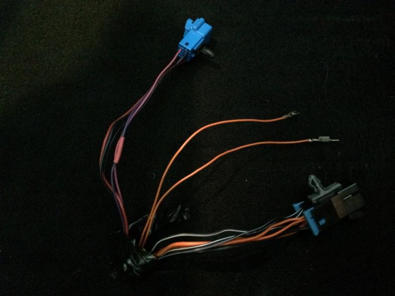
About a week ago I replaced the seat adjuster control cover on my wife's 2002 corvette driver side seat. Put the seat back in, and everything was going good until I moved the seat. Then a few of the wires got pulled out of the connectors, and one got cut.
I have all but two orange wires back in the connectors. These two orange wires go into the "E" and "G" slot of the blue connector. See above photo.
I think one of these orange wires go to the telescoping actuator switch, and the other goes to the telescoping sensor???? But I do not know how to check or test to confirm which one is which.
Any help would certainly be appreciated.
 11-09-2014, 08:32 AM
#2
Le Mans Master


Need some info since I don't know what connector was damaged. How many pins are in the connector of concern? What are wire colors and pin ID locations for those still in place? I should be able to ID the connector from that info.
Once we figure out the connector in question we can determine how to ID the circuits.
Are the pins too damaged to be reused? You may have to replace them if they are. There are sources.
Once we figure out the connector in question we can determine how to ID the circuits.
Are the pins too damaged to be reused? You may have to replace them if they are. There are sources.
11-09-2014, 08:36 AM
#3
Le Mans Master
The Forum edit function is hosed up at the moment. When I said "How many pins are in the connector of concern?" I wanted to know how many opening are in the connector (like 6, etc.) even if they are not all used.
11-09-2014, 11:38 AM
#4
Cruising
Thread Starter
Member Since: Nov 2014
Location: Castaic CA
Posts: 13
Likes: 0
Received 0 Likes
on
0 Posts
Here is the wire configuration in the blue connector:
Position A - Red Wire
Position B - Black (heavier gauge)
Position C - Purple
Position D - Black (smaller gauge)
Position E - Open - one of the Orange Wires
Position F - Pink
Position G - Open - one of the Orange Wires
11-10-2014, 07:34 AM
#5
Le Mans Master
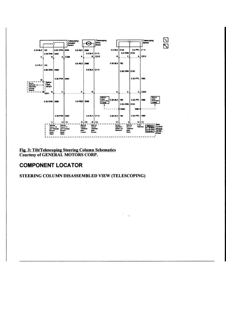
I have looked thru all the possible connectors in my 2001 FSM. The only one that appears to be a match is C303 which interfaces between the steering column and the SCM. I am sure that is the one we are dealing with.
All the wire colors and positions match with this clarification:
It only shows one Orange wire at pin G for the power to move the column "out".
Also, pin E is shown as White and is for the Telescoping Position Signal.
Not sure I can get access to a 2002 FSM but I would be amazed if it were different. In particular, Orange is NEVER used for a sensor signal.
We may need to discuss this over the phone to figure out what is going on. You are welcome to PM me with your number if you like. There has to be a logical reason for the mismatch.
11-10-2014, 08:01 AM
#6
Le Mans Master
Tried to edit my previous post but this Forum's edit feature is still hosed up. I knew when I said they never use Orange for a sensor wire I would somehow be proven wrong. I did find that in 2004 they used an Orange wire for the sensor. I can only assume they did that from 2002-2004.
I have the info for pin outs for each of the two different connectors they go to so you can do a continuity check and verify which one is which. Will try to post a little later after I take my daughter to school.
Learning something every day, the hard way.
I have the info for pin outs for each of the two different connectors they go to so you can do a continuity check and verify which one is which. Will try to post a little later after I take my daughter to school.
Learning something every day, the hard way.
11-10-2014, 08:14 AM
#7
Le Mans Master
Here is the schematic for checking out the circuits. If you can't read it I can email you a copy that might be better than a link. Let me know if I can do anything else.
BTW, where did you get the replacement pins?
BTW, where did you get the replacement pins?
 11-10-2014, 11:40 AM
#8
Cruising
Thread Starter
Member Since: Nov 2014
Location: Castaic CA
Posts: 13
Likes: 0
Received 0 Likes
on
0 Posts
I purchased the pins at electricalhub.com.
06-08-2016, 11:57 PM
#10

[QUOTE=RickJennings;1588220836]Attachment 47839267
About a week ago I replaced the seat adjuster control cover on my wife's 2002 corvette driver side seat. Put the seat back in, and everything was going good until I moved the seat. Then a few of the wires got pulled out of the connectors, and one got cut.
I have all but two orange wires back in the connectors. These two orange wires go into the "E" and "G" slot of the blue connector. See above photo.
I think one of these orange wires go to the telescoping actuator switch, and the other goes to the telescoping sensor???? But I do not know how to check or test to confirm which one is which.
Any help would certainly be appreciated.[/QUOT
L
Hi there, My 2002 vert had drivers seat intermittent movement failure. I bought a connector and while taking the seat out I color coded and labeled all wire to wire so reconnecting the new connector was a no brainer.
This spring the intermittent movement started failing again. I could not get the seat to move electrically so I was forced to disconnect the wires from the connector before removing the seat, not being able to mark the wires for re-connecting Ive left myself with the
NOTE IM GUESSING ON GAUGE OF WIRE TO SHOW
DIFFERENT GAUGE SIZE 8 BEING LARGEST
7 wires from the FLOOR
1 brn wht / 2 blk wht /
let's say 1 8 GA ORNG / 1 6 GA ORNG / 1 4 GA ORNG
and let's say 1 8 GA BLK /
I'm using 8 ga as the biggest wire.
6 wires from the SEAT
1 brn wht / blk wht /
1 8 GA ORNG / 1 6 GA ORNG / 1 4 GA ORNG
1 8 GA BLK
Three months ago these wires were connected and the drivers seat moved fine. Now.
I have these wires posi locked and tucked under the seat. I have no idea how to reconnect these wires. Oh and the original connector is long gone because of my inexperience on the first reconnect. Now of corse I would have to signal electronics and ordered the original connector pins and pin tool.
If anyone can help the way I was able to get the help I needed on vet forum reinstalling my falling out vert back window. Oh and completely stop my vert driver side to stop leaking.
Thanks, Ken