When you click on links to various merchants on this site and make a purchase, this can result in this site earning a commission. Affiliate programs and affiliations include, but are not limited to, the eBay Partner Network.
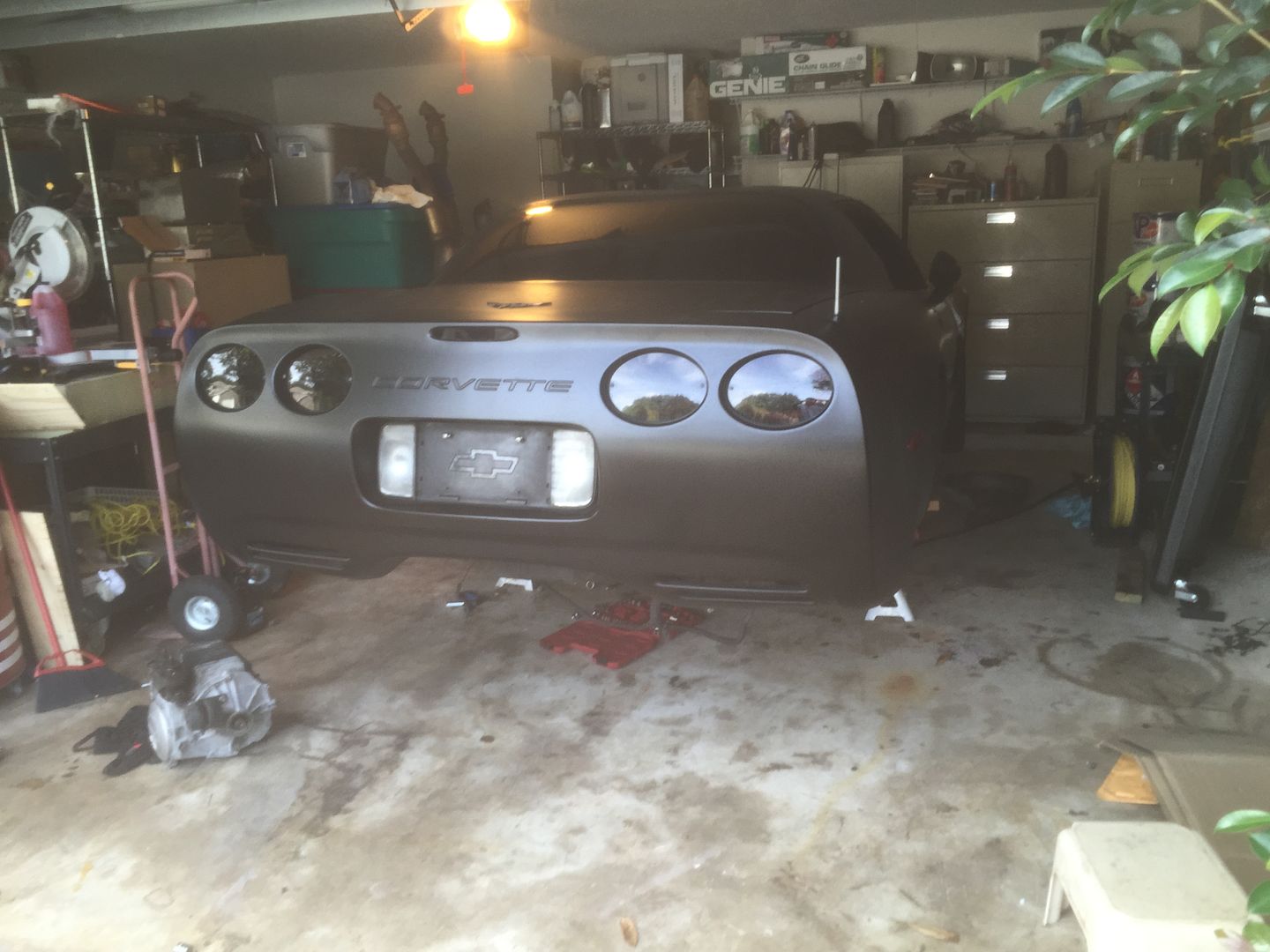
Hello all, i recently purchased my first corvette, a matte black 2001 z06, and i have a bunch of questions. It doesnt drive atm.
Does anyone with a c5 repair manual mind sending me pictures or copies of the pages on transaxle and clutch removal and install? Found a decent write up but need more detail and torque specs.
I am not very familiar with chevys, clutches, transmissions, and especially not transaxles, but i will try to keep the silly questions to a minimum.
I have a spare transmission that was checked out and works so im good there, but how can i check if the throwout bearing is bad? Is the bearing any different for a ls7 clutch? My clutch is good but if i have to take apart the bellhousing ill want to upgrade.
The drivetrain on the car has problems, when the engine is running there is a thud about every 1/4 sec. Not sure what is causing this but when i get under the car and spin the wheel i hear the same thud coming from the transaxle
Second problem, whenever the clutch is let out, there is a very bad binding noise. Throwout bearing?
Third problem, the shifter engages gears forward and back but is completely detatched side to side. Only 3rd and 4th can be selected and the shifter still moves as if in neutral. Probably a broken shifter linkage but of course those cant be accessed without dropping the transaxle. Do they go through the torque tube?
Just trying to figure out what i need to order to get this thing on the road, all suggestions welcome, thanks guys!
Last edited by Coorvette; 11-10-2015 at 01:08 PM.
Reason: thanks k24556
The throwout bearing is just a bearing. Turning rough or dry means it's bad just like any other bearing.
The LS7 clutch still uses the C5 throwout bearing and slave cylinder.
The noises could be related. You'll have to pull the drivetrain and look for an issue. It could be a broken output shaft in the differential, a broken input or output shaft in the transmission, damage to the driveshaft in the torque tube or damage to the clutch.
The shifter could be in the transmission or it could be damage to the shifter. Take the console apart and check out the shifter setup. The linkage is a single shaft that twists and moves forwards and backwards to select all gears. Something loose or damaged in the shifter could cause it to not select the gears properly.
Just replace slave cylinder(comes with t/o brg) and clutch master. Fluid is prob black as hell in reservoir. Add remote bleeder with that. The ls7 clutch will make pedal a lot stiffer! Also need a spacer for slave. Should also consider u-joints (couplers) if have a lot of miles and with noise going to want to pull driveshaft out of torque tube and inspect anyway. Is your trans from a Z? They have diff ratios than non Z trannies.
The throwout bearing is just a bearing. Turning rough or dry means it's bad just like any other bearing.
The LS7 clutch still uses the C5 throwout bearing and slave cylinder.
The noises could be related. You'll have to pull the drivetrain and look for an issue. It could be a broken output shaft in the differential, a broken input or output shaft in the transmission, damage to the driveshaft in the torque tube or damage to the clutch.
The shifter could be in the transmission or it could be damage to the shifter. Take the console apart and check out the shifter setup. The linkage is a single shaft that twists and moves forwards and backwards to select all gears. Something loose or damaged in the shifter could cause it to not select the gears properly.
Originally Posted by 3musky3
Just replace slave cylinder(comes with t/o brg) and clutch master. Fluid is prob black as hell in reservoir. Add remote bleeder with that. The ls7 clutch will make pedal a lot stiffer! Also need a spacer for slave. Should also consider u-joints (couplers) if have a lot of miles and with noise going to want to pull driveshaft out of torque tube and inspect anyway. Is your trans from a Z? They have diff ratios than non Z trannies.
Thanks guys,
Yes I took apart the console and checked out the shifter and its all aligned and tight, I guess it must have broken at the transmission, but how and why I don't know. It actually already has a new slave and remote bleeder, but was vacuum bleed and had problems bleeding completely so I want to replace it. I'm not sure if the new trans is a c5z but it came with a diff, do c5 6 spds have all different ratios or just final drive? Can you tell me more about the spacer? will installing a ls6 slave with a spacer interfere with transaxle installation? Would an ls7 slave need the spacer or any modification? Aftermarket FX racing slave?
So just to make sure im not forgetting anything, I will need the following(or equivalent). I think ill order the cultrag performance kit with the fidanza flywheel and arp flywheel and pressure plate bolts.
ls7 clutch
ls7 pressure plate
ls7 flywheel
ls6 slave w/ throw out bearing & spacer
pilot bearing
driveshaft couplers
What do I need to know about balancing the flywheel? I know they are balanced to 0. Am I supposed to transfer the balancing weights?
Sorry to ask more questions, ive been reading so much my eyes hurt from staring at the screen.
Thanks again!,
David
WOW! If this was my car, I would break the drive train down to PARADE REST and inspect EVERYTHING!
Sounds like you are in for a real treat!
BALANCE is very important so, you will need to reference mark the flywheel to the crank. The OEM installed weights need to be transferred to the new flywheel OR the new flywheel needs to be OFF SET BALANCED to match the off set weights that were added to the rim holes.
Disassemble your TT and inspect the bearings and couplers.
You need a NEW pilot bearing! PERIOD!
Before you rip out the drivetrain put the trans in "N", jack up one rear wheel. Attempt to rotate that wheel. It SHOULD have some break away resistance to rotation (approx 40 ft/lbs) as you are slipping the differential limited slip clutches.
Do the same to the other wheel.
If you have little or no resistance, you most likely have a busted beleivew spring OR the clutches are shot!
Jack up BOTH wheels and see if the wheels turn together smoothly.
You can check the rear wheel bearings by push/pulling the wheel at the 3-9 and 12-6 positions. There should be little to no slop in the wheel hub bearings.
Here are some post to read about the differential and output shafts and transmission guts.
made a copy some time back,,,lots of info-- hope it helps along with the suggestions from CF members
mike v
C5 & C6 CORVETTE CLUTCH INSTALLATION
Depending on the driving style of the owner, manual transmission clutches can be subjected to a lot of abuse. An owner can wear the disc linings out in just a few days or even within hours. How quickly the clutch pedal is released determines how long the clutch disc will last. Those with a tendency to let the clutch out slowly or leave slight pressure on the clutch pedal clutch disc will experience rapid clutch wear. Living in mountainous areas also works the clutch assembly harder, as owners are fighting the forces of gravity when attempting to roll away from a stop going uphill.
Choosing the correct clutch assembly is important for long life and driving ease. This is especially true if plans are made to increase power or frequent the local drag strips (road racing or Gymkhana events are not as rough on the clutch assembly).
The clutch disc uses a metallic center plate with a complex friction material bonded to it. Rivets are used to bond the friction material to the metallic disc. Clutch discs have dampening springs in the center, sandwiched between the outer plate and inner hub. The dampening springs allow the outer plate lined with friction material to rotate slightly on the inner hub during engagement. The inner hub is splined to the transmission’s input main shaft, propelling a Corvette down the road. The dampening springs absorb the shock of the torque loading as the clutch fully engages. Matching the correct dampening springs and friction material to vehicle usage is very important to allow smooth engagement.
Pressure plates are spring loaded devices that clamp the clutch friction disc to the flywheel. As you can imagine, it takes quite a lot of spring clamping force to propel a 3000-pound vehicle down the road. Pressure plates come in two forms for most automotive uses. GM has used diaphragm pressure plates equipped with a belleville spring (coned metallic disc that can be over-centered using relatively light force) to apply clamping load for C3, 4, 5 and 6 Corvettes. Once they spring back from over-centering, they clamp very well. This diaphragm style clutch also works well with hydraulic clutches used today.
Borg & Beck three-finger style clutches are commonly used with mechanical clutch linkages. The Borg & Beck pressure plates use coil springs to apply disc clamping force. The three-fingers work similarly, using levers to over-center and disengage the clutch. The downside to Borg & Beck clutches is effort. Their design takes more pedal effort for the same clamping force as the diaphragm clutch. Because of the additional effort required, the Borg & Beck works better with a mechanical clutch linkage. The upside to the Borg & Beck style clutch is that it will engage at high RPM without fail.
Diaphragm clutches have a tendency to stay disengaged at high RPM, especially if the clutch is out of adjustment. Before there were hydraulic clutches, it was common to find the clutch pedal still on the floor while attempting to shift through the gears at high RPM. We found that adjusting the clutch so that it just barely disengaged helped prevent stuck pedals. Centrifugal force would prevent the belleville spring from over-centering if it went beyond a certain point. Hydraulic clutches will not allow for adjustments, so the clutch manufacturers have had to work their magic to prevent sticking clutch pedals. They have to precisely measure the final clutch stack to limit any excess belleville spring movement.
Buying the Correct Clutch
Clutch manufacturers have to consider many possible scenarios during the design stage. Customers want a clutch that grabs smoothly with the least amount of pedal effort. City traffic and gridlock quickly gets old when dealing with high clutch pedal effort. Those who plan on hard launches in their C5 will want to strongly consider a performance clutch assembly. Sticky tires will also need to be figured into the equation. Once you have the variables considered, ask questions. We have plenty of options from stock replacement to Fidanza and Ram performance clutch assemblies. Remember: aggressive clutches will grab quickly and can chatter depending on how the clutch pedal is released.
Common Clutch Problems
Clutch chatter is usually caused from warped clutch discs and pressure plates or (less likely) oil and grease contamination. To date, we have never witnessed anyone complaining of oil or grease contamination with their C5 or C6. Because of the rear transaxle, there is no way of getting transmission fluid on the clutch assembly.
Slippage is what occurs when engine RPM is increasing on a slight grade, but your Corvette is losing speed. This is usually due to clutch disc friction material loss. High RPM banzai runs can shuck the friction material off instantly. Typical wear from usage is noticed when the clutch pedal is almost fully released before the Corvette starts to move.
Vibration is usually the next symptom of clutch slippage. When big pieces of friction material come off the clutch, disc vibration occurs. In most cases, the Corvette is not able to move under its own power from a slipping clutch disc before the vibration is noticed. The clutch is ready to give up the ghost when you notice slippage and then vibration. At that point, the best thing to do is nurse your Corvette home and check into a new clutch assembly.
Gear clashing during shifting can be due to the clutch assembly. When you are shifting through the gears, the input shaft slows down upon clutch disengagement. Input shaft slowdown allows the transmission to shift easier, as the upshifted gear ratio is closer in speed to the previous gear. The input shaft can drag for a couple of reasons. Contamination from oil or grease can cause the clutch disc to drag on the flywheel or pressure plate. Pilot bearings can also cause drag if the bearing has gone bad or the lubricant has dried up. As the input shaft drag worsens, shifting into first and reverse can become very difficult.
Replacing the Clutch
Tools needed:
• 8mm socket
• 10mm socket
• 13mm socket
• 15mm socket
• 18mm socket
• 21mm socket
• 24mm socket
• Torx T15 bit
• Torx T30 bit
• Flywheel tool (recommended)
• large C-clamp
• transmission jack (2 recommended)
• jack stands
• Ford A/C and fuel line disconnect tool
• new clutch and flywheel
• remote fluid bleeder
• slave cylinder, Corvette Central part #535050
• 4.1 quarts GM Syncromesh, Corvette Central part #531196
• Blue Loctite
• clutch alignment tool
• (2) 16 oz. bottles of brake fluid
• small vice grips
• flat screwdriver
Torque specifications:
• Slave: 106 inch lbs.
• Flywheel: 15 ft/lbs; 37ft/lbs; 74 ft/lbs with blue Loctite
• Factory pressure plate specifications: 20 ft/lbs; 30 ft/lbs; 50 ft/lbs (aftermarket will differ)
C5 or C6 Corvette clutch replacement may seem daunting. The challenge is pulling the entire driveline (from the torque tube at the bell housing to the differential). The entire assembly comes out of the underside. There are eight bolts that retain the rear upper control arms and shocks to the chassis. Four nuts retain the cradle to the chassis. Once these nuts are removed, the entire assembly will drop (including all suspension pieces with the differential and transmission. Of course there are a few wire and lines to remove first).
No access to a lift? If you raise the rear of your C5 to the correct height, the differential, transmission and torque tube can be lowered onto the wheels and rolled back far enough for clutch replacement. Make provisions to get the car at least 2′ in the air. Positioning the jack stands will take some thought, but it is possible to remove the entire assembly in this manner.
The following photos illustrate how the drivetrain is disassembled and reassembled.
This is where it starts: removing the shifter. The shifter bolts to the torque tube from the top side under the shift boot.
The panel that houses the traction control switch is removed by carefully prying it out of the console. Disconnect the wires and set it aside.
We remove the console compartment as an assembly. There are screws at the rear under plastic caps that must be removed. Two 10MM nuts are removed from the front and the console is out of the way.
Pop the a/c inside temperature probe cover off to remove the T15 torx bit screw holding the center fascia.
Carefully pry the shift emblem out of the shifter ****.
A wedge is used to secure the shifter **** after it is screwed down. The interference fit wedge can be difficult to remove. Wiggling it can help get it loose. Watch that shifter ball leather!
Unscrew the **** counter-clockwise.
Remove the center console plate and dash fascia. You will need to disconnect the lighter at the rear of the plate.
Remove the 10MM nuts that retain the shift boot.
Remove the shifter for replacement with an aftermarket assembly (optional). You do not need to remove the four 10MM screws as shown unless you are replacing the shifter.
Remove the rear wheels. Next, remove the rear brake calipers (15mm socket required, 2 bolts for each caliper). It is always a good idea to tie-off the calipers. Do not leave them dangling from the brake hoses.
Remove the two 13mm bolts from the top of the shock (recommended), or from the single 24mm nut and bolt on the bottom. Next, remove the two 18mm bolts from the top of the upper control arm (recommended), or remove the upper ball joint as an alternative. Remove the halfshaft from the differential with a pry tool. Disconnect the 2-pin wiring harness located near the emergency brake.
Remove the two 15mm bolts that hold the emergency brake bracket. Proceed to remove the emergency brake cable from the rear of the spindle, and remove the emergency brake cable from the bracket (important: 3 tabs must be pressed. Use a small set of vice grips to hold two tabs in place as you press on the third with a flat screwdriver). Depending on what year you are working with, the anti-lock brake system module wiring must be removed. The rear wheel speed sensor wiring must be disconnected and moved out of the way. Rear brake lines must be unclipped from their places on the rear cradle. Finally, the four 21MM cradle bolts are removed after making sure everything is supported properly. Repeat this entire procedure for the other side.
Now to the underside to remove the exhaust system.
For muffler removal clearance reasons, the 18MM sway bar nuts are removed from the mounts. Let the sway bar hang. Disconnect the 2 15mm bolts that hold the over-axle pipes to the center pipe. Zip tie through these holes onto a nearby bolt (look for one on the side of the tunnel) to get these out of the way. Pull the center pipe. Note that there are two 13mm bolts hanging from springs near the back. Pay close attention to the O2 sensors. Remove the clips on the sides of the tunnel to prevent from stretching the wires.
Remove the 13MM exhaust hanger nuts. Hold onto the muffler, as it is ready for removal.
Now is the time to replace that stock exhaust system with one of our Magnaflow exhaust kits. The muffler and exhaust pipe is rolled out over the CV axleshaft.
You need enough room to let the muffler go straight down to get it out completely. A reciprocating saw makes it easy to remove if you decide on a new system. Do not forget about the seals for the front to rear pipes (Corvette Central part number 325123).
These clips hold the rear oxygen sensor harnesses to the tunnel shield. The connectors for the oxygen sensors are up at the front near the exhaust manifolds. While you’re in the area, you can remove the two 15MM horizontal bolts that hold the front pipe assembly to the torque tube.
There are three 15MM nuts on each exhaust manifold connection that must be removed. If you have headers, remove the five 10mm bolts from each header flange and swing them out of position. Hold them in place with straps or bungee cords.
There are also rear exhaust pipe hangers to be removed.
Once the exhaust is out of the way, remove the multitude of 8MM screws holding the center heat shield in place.
Remove the intake tubing from the throttle body before lowering the drivetrain (not pictured). It is recommended to have two transmission jacks to lower the drivetrain. Place one under the rear suspension cradle and one beneath the transmission. Remove the four 21mm bolts for the rear suspension cradle. Note: do NOT use an impact tool for this step, as an impact tool will break the retaining rivets for the nuts (meaning you will have to remove carpeting and cut a hole in the floorpan). To begin removal of the assembly, remove all but two bolts that are used to retain the torque tube to the bellhousing. Slowly begin to lower the rear end. You will need to carefully watch for parts to disconnect, like the differential wiring harness. The brake lines will pass between the rear differential and the halfshafts. Then the jack is lowered slowly to allow the engine to angle back and stop at the firewall. Do NOT let the engine rest against the firewall, as damage will occur. With the differential supported, have a helper remove the last two torque tube to bellhousing bolts. Move the complete assembly away from the bellhousing while the front of the torque tube is held up by your helper. The torque tube is not heavy at this point. Move the assembly out of the way and be sure to support the torque tube until you’re ready to install the assembly.
Disconnect the fitting leading to the slave (it’s a steel braided line with a big brass cylinder in the middle of it, towards the driver’s side of the car, coming out of the very end of the torque tube near the bellhousing). A Ford air conditioning + fuel line coupling disconnect tool is a great time-saving tool for this procedure. Using the 5/8″ version, push in the white (turns to grey if the Corvette has higher mileage) collar on the brass cylinder that is facing towards the front of the car. Once the white collar is completely pushed in, the line will release.
Remove the 13mm bolts at the end of the torque tube to the bellhousing. At this point, measure the height of the rear cradle and transmission and/or the jacks. Take a measurement at the front and rear, as the height will vary slightly at each end. This will make it easier when it comes time to reassemble everything. Place a bottle jack underneath the oil pan to keep the engine from tilting upon removing the torque tube. Pull the torque tube and rear assembly backwards until the shaft at the end of the tube is clear of the bellhousing.
Remove the large wiring harness from the top of the torque tube, in addition to several connectors on the transmission.Completely lower the transmission jacks so that everything will clear upon removal. Observe the shifter base during this step, as it can catch the lines on the driver side of the tunnel. Slow and steady is the key here. Once lowered, position the assembly away from the underside of the car for more space. This is a prime opportunity to replace the slave cylinder (our part number 535050 slave cylinder and release bearing assembly is a direct replacement) and add a remote bleeder extension (pictured is the Tick Performance Speed Bleeder).
The rear cradle allows you balance the assembly on a transmission jack easier than the differential itself.
This torque tube photo shows the shifter mounted on the tube with the stick removed. We typically remove the three T30 torx bit screws and remove the complete shifter. The shifter has two torx bit screws and the linkage has one in the rod clamp. For orientation purposes, the left side of the photo is the engine side of the tube. If needed, service the release bearing and hydraulic clutch release cylinder.
If desired, remove the 13mm bolts from the bellhousing and pull the bellhousing. It is not necessary to do this.
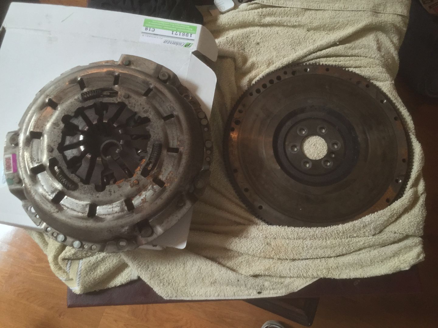
Replacement is like a traditional clutch at this point. Remove the six 13mm pressure plate bolts. The pressure plate bolts should be removed, a couple of turns at a time, in a criss-cross pattern. This evenly releases pressure on the clutch disc and plate. NOTE: the pressure plate and the clutch disc will come out after removing the bolts. Next, remove the 6 15mm flywheel bolts and remove the flywheel.
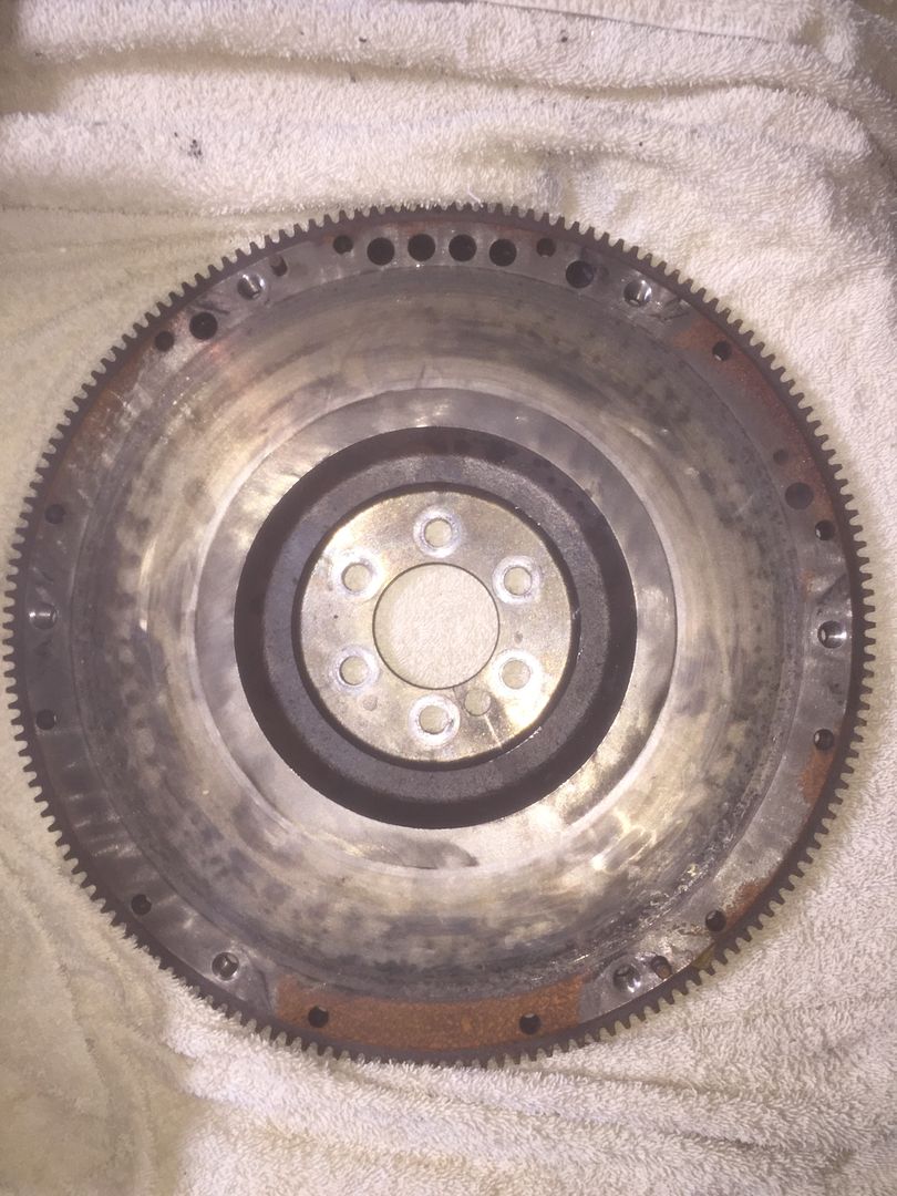
If the flywheel is checked with hot spots (super hot metal smearing across the flywheel face and then balling up), it should be resurfaced. These hot spots are extremely hard and sometimes will not machine out. The machine tool skips over the hard spot preventing a smooth engagement surface. You should only remove .020 of material from the surface. Something to consider is, has the flywheel been machined in the past?
After the main assembly is out of the way, the lower bellhousing cover is removed to reveal the clutch assembly. At this point you can also remove the bellhousing to get at the clutch pressure plate bolts easier.
This clutch assembly is from an earlier Corvette. The clutch disc lining has been thrown off from high RPM. The flywheel clutch surface is full of check marks (hotspots) questioning the possibility of resurfacing the flywheel. Of course the pressure plate is junk.
All flywheels have a tendency to cone outward from pressure plate applied forces. Here we are checking to see how bad the cone is with a feeler gauge. Hydraulic clutches have limited travel. Excessive flywheel machining can cause clutch disengagement problems. We use .020 as our maximum allowed machining of the flywheel friction face.
Once the flywheel is torqued and ready for the clutch assembly, wash the machined surfaces with brake cleaner or alcohol. This step is often missed, causing clutch chatter from the contaminated surfaces.
Installing the flywheel takes some care to avoid rear main seal oil leaks from crankshaft hub distortion. Clean the flywheel bolts with brake cleaner and apply blue Loctite to the threads before installation. A torque wrench should be used to incrementally tighten the flywheel to crankshaft bolts in a star pattern. Torque the bolts to 15 lb/ft on the first pass, 37 lb/ft on the second pass and 74 lb/ft to finish (see above pic).
Put the clutch disc in the pressure plate and place both parts against the flywheel. Hand tighten the 6 bolts. Find the alignment tool (provided with your new clutch in most cases; if not, an old input shaft will work as a substitute). Position the alignment tool through the pressure plate, the clutch disc, and into the pilot bearing. Tighten the bolts in a criss-cross pattern with 2-3 steps. Note: the factory final torque specification is 50 ft/lbs. NOTE: If an aftermarket clutch is being used, make sure to verify the final torque specs, as they will differ from the factory specs. Failure to do this may result in broken bolts.
When you’re done, the alignment tool should easily slide in and out. Realign if it does not. Tip: hand tighten the bolts, wiggling the alignment tool, then slowly tighten the bolts (give the tool a wiggle every once in a while to check the tension on it).
If needed, service the release bearing and hydraulic clutch release cylinder. Our part number 535050 slave cylinder and release bearing assembly is a direct replacement . The addition of an aftermarket bleeder extension would be ideal here. The throwout bearing is attached it via a large spring. To remove the bearing, push it in and rotate it counterclockwise until it pops out.
Now is the best time to replace the transmission fluid. Once the transmission is back in place, a pump must be used to fill the unit. We have part number 531196 GM Synchromesh transmission fluid available for a factory fill. B&M Trick shift fluid is also available for high RPM shifting under part number 533218.
Assembly reinstall
First, completely lower the transmission jacks. Slide the assembly under the car until the tip of the input shaft is positioned near the bellhousing opening. Find the height measurements that you took during disassembly. Begin to raise the jacks slowly. Alternate raising each jack , as a single jack cannot support the entire weight of the drivetrain. If available, use a bottle jack at the end of the torque tube to aid in lining up the input shaft with the clutch assembly. Put some lithium grease on the input shaft to prevent squeaks and aid in reassembly. Avoid getting grease on the clutch at all costs.
Once the jacks are at their correct height, and the input shaft looks lined up, start pulling, push the drivetrain into place. It is strongly recommended to have two people complete this task. It is critical that the splines are correctly lined up. Use a large C-clamp to hold the end of the torque tube and the end of the drivetrain together. Crank the C-clamp down to draw the drivetrain into the clutch.
The input shaft must go through the clutch disc grooves and into the pilot bearing. Keep turning the flywheel in tiny increments until they mesh. The input shaft will slide into position when it is just right. Continue to pull the torque tube and drivetrain closer together. Important: As you get closer, take extra care to ensure that the drivetrain is angled and leveled correctly (use a level on the rear swaybar to verify). After this, use the bellhousing bolts to pull the parts together. Take caution not to tighten the bolts before you are certain that everything is aligned, otherwise you run the risk of crossthreading (and ruining) the bolts in the bell housingReconnect and tighten all connectors and bolts that were separated earlier. Take extra care to ensure that the wiring above the torque tube is not pinched. Also, watch the wiring harness located near the rear mufflers so that they do not touch the exhaust pipe.
Once the assembly is buttoned up, bleed the clutch cylinder and you’re ready to go enjoy the extra grip from your new clutch.
First thing I suggest you do is go into the edit mode in your original post and delete your phone number and email. While all the regulars here are honest people, you have given out some info you may not want the whole world to know. the edit button is just below the typing area to the right.
Some of your descriptions are a bit on the vague side, like "a thud ever 1/4 second" is that with the clutch out and the trans in neutral with the wheels off the ground? Everyone here will be happy to help you and have helped me greatly too. Before you go tearing into the car and disabling your ability to trouble shoot, try to isolate what you are seeing, hearing and feeling.
Not sure what a binding noise is in the clutch, but if either the pilot bearing or the throwout bearing is bad, you will get noise with the clutch out and the trans in neutral. The throwout bearing has a plastic retainer behind it that can melt and cause problems, and there are aftermarket solutions for that. The throwout bearing is generally not serviceable by itself, but comes with a new slave cylinder.
Your shifting problems can be as simple as adjusting. The adjustment can be done from the driver's seat, but you must remove the console to get to the shifter. You will find plenty of posts regarding getting to the adjustment. Your problem might be as simple as getting the linkage adjusted properly and some of your noise may be the linkage binding the internals of the trans. By the way, the shifter "Box" is mounted outside the torque tube and the shift linkage is one rod that is also outside the torque tube but really close to it.
Here are two files to help you. One is the linkage adjust procedure, the other the torque values you requested.
edited
The thud is there even when the clutch is in, in neutral, with the wheels off the ground. sounded like it was coming from the transaxle. I didn't get under the car to listen for it before I took the exhaust off and now its hard to hear. I think I will try using a car stethoscope to isolate it.
To try to fix the binding I already tried the adjustment, the shifter linkage is just complete broken at the other end. I also think the binding may be one of those bearings, might the aftermarket slave cylinder I posted also have a aftermarket slave cyl as well?
Originally Posted by mike venth
made a copy some time back,,,lots of info-- hope it helps along with the suggestions from CF members
mike v
Very detailed info, thanks a ton!
Originally Posted by Bill Curlee
WOW! If this was my car, I would break the drive train down to PARADE REST and inspect EVERYTHING!
Sounds like you are in for a real treat!
BALANCE is very important so, you will need to reference mark the flywheel to the crank. The OEM installed weights need to be transferred to the new flywheel OR the new flywheel needs to be OFF SET BALANCED to match the off set weights that were added to the rim holes.
Disassemble your TT and inspect the bearings and couplers.
You need a NEW pilot bearing! PERIOD!
Before you rip out the drivetrain put the trans in "N", jack up one rear wheel. Attempt to rotate that wheel. It SHOULD have some break away resistance to rotation (approx 40 ft/lbs) as you are slipping the differential limited slip clutches.
Do the same to the other wheel.
If you have little or no resistance, you most likely have a busted beleivew spring OR the clutches are shot!
Jack up BOTH wheels and see if the wheels turn together smoothly.
You can check the rear wheel bearings by push/pulling the wheel at the 3-9 and 12-6 positions. There should be little to no slop in the wheel hub bearings.
Here are some post to read about the differential and output shafts and transmission guts.
It is sounding that way, I've come to the same conclusion im going to rebuild everything Thanks, I give those things a try, and for the info on balancing. Although I don't think the issues are with the diff or wheel bearings.
Updated list:
OEM ls7 clutch
OEM ls7 pressure plate
Fidanza ls7 flywheel
OEM ls6 slave w/ throw out bearing & spacer
OEM pilot bearing
OEM driveshaft couplers
OEM torque tube bearings, front and back
Thanks guys, it turned out it was the rusted pins and I was able to pry them loose and the transmission came off.
I'm now trying to install the new LS7 flywheel, clutch, and pp can't find a place to have the new unit balanced. Apparently my LS6 may be externally balanced because on the flywheel there is nothing in any of the balancing slots, but instead there are 8 holes drilled into one side of the flywheel. I know my only option is to take the old & new clutch assemblies to a machine shop, and find out whether the holes were drilled to balance it to neutral or match the unit being replaced.
Anyone know of any shops in Jacksonville that balance flywheels/pp?

 11-08-2015, 05:17 PM


 edited