
Voltage 13.6 to 18.0 and Higher
 07-24-2016, 09:27 PM
#1


Ripley's Believe it or Not !!!!!
Tested my battery 12.0 volts .... Tested my Alternator 14/15 volts .... These readings are in the evening when the sun has set and it's cooler outside. Now, when I start the car during the middle of the day the sun is blasting hot and it's dang hot out there. On my DIC volts are 18 and higher my gauges drop off line and shut down. But when I test Batt and alternator 14 to 15 volts while car is started and running. What's going on with my 2004 C5?
RAiN 1999
 07-24-2016, 10:32 PM
#2
Le Mans Master

12 volts would be a drained battery....have your battery load tested
Check your connections on the starter...look for corroded, burnt, loose...
Check your grounds...
C5 battery charge loss chart
A fully charged battery should be 12.6v or more.
If the battery is
12.5 = 85% charged
12.4 = 65%
12.3 = 50%
12.2 = 35%
12.1 = drained
Check your connections on the starter...look for corroded, burnt, loose...
Check your grounds...
C5 battery charge loss chart
A fully charged battery should be 12.6v or more.
If the battery is
12.5 = 85% charged
12.4 = 65%
12.3 = 50%
12.2 = 35%
12.1 = drained
Last edited by 73Corvette; 07-24-2016 at 10:34 PM.
07-24-2016, 10:48 PM
#3
Thx Sir, checked my Batt again 12.5 ... Just looked at my starter, everything is tight but connections appear to have some corrosion and as I was checking things out the plastic under the connection leads appears to move while trying to remove nut on connections .... Should it move? Exhaust is in the way does it require dropping the exhaust to get to the starter?
Last edited by RAiN 1999; 07-24-2016 at 10:49 PM.
07-25-2016, 11:48 AM
#4
1/4 mile/AutoX

Do not just replace the alternator with a rebuild !!!!!
Last edited by Pounder; 07-25-2016 at 11:48 AM.
07-25-2016, 11:55 AM
#5
Tech Contributor


Member Since: Dec 1999
Location: Anthony TX
Posts: 32,736
Received 2,180 Likes
on
1,583 Posts
CI 6,7,8,9,11 Vet
St. Jude Donor '08

The JUNCTION on the starter main lug contains three wires. In of the wires is an alternator voltage feedback wire. If the alternator doesn't get feed back from that terminal it will max out voltage.
That terminal needs to be clean and tight and NO, the plastic end cap should NOYT move or be cracked!
Te wires need to be clean and tight!
BC
That terminal needs to be clean and tight and NO, the plastic end cap should NOYT move or be cracked!
Te wires need to be clean and tight!
BC
07-28-2016, 12:58 PM
#8
The JUNCTION on the starter main lug contains three wires. In of the wires is an alternator voltage feedback wire. If the alternator doesn't get feed back from that terminal it will max out voltage.
That terminal needs to be clean and tight and NO, the plastic end cap should NOYT move or be cracked!
Te wires need to be clean and tight!
BC
That terminal needs to be clean and tight and NO, the plastic end cap should NOYT move or be cracked!
Te wires need to be clean and tight!
BC
Removed all three wires on starter cleaned removed corrosion and reinstalled tight .... I still have the same problem High voltage. I checked the volts on the batt 12.5 and with the car running 14.6 coming back from the voltage regulator, not throwing any codes (none). Any more ideas I would greatly appreciate it.
RAiN 1999
07-28-2016, 01:35 PM
#9
Le Mans Master
If I were in your shoes I'd have my alternator rebuilt... but, I have a VERY reputable shop that does top notch work with a quick turn around... don't know your situation... 
07-28-2016, 02:14 PM
#10
RAin 1999
07-28-2016, 02:44 PM
#11
Le Mans Master
8vette7 knows WAY more than I do... so listen to him and do whatever he ask ... he'll get you fixed up ... Thanks Chuck I don't want to lead someone down the wrong path...
07-28-2016, 03:12 PM
#12
[QUOTE=8VETTE7;1592726004]No need to have the alternator rebuilt. OP's post indicates it is putting out 14.6 volts at the back of the alternator so it seems it should be OK.
After re-reading your post I am unsure if you are saying you measured the both the battery voltage and the alternator voltage with the car running. The remainder of my post is assuming that you DID measure both with the engine running. Either way you need to verify the condition of the two wires (both red in the diagram below) to insure that they are good end to end. One provides alternator output voltage to the battery to charge it and the other is for a sensing circuit in the alternator.
Voltage is OK at the back of the alternator but is obviously NOT getting to the battery. The path from the alternator to the battery is through the connections at the starter solenoid. So there is a breakdown in the
electrical path somewhere. Either the wire from the alternator to the solenoid is bad (there is a fuseable link as shown in the diagram below) or the connection of the wire to the lug that connects to the post on the battery is bad. Really can't be the wire from the solenoid to the battery or the car would not start. Here is a diagram that should help:
Attachment 48004253[/QUOTE
8VETTE7,
I fully understand what you are saying ... I measured my batt static not running 12.5 I measured the Alt & batt also while running 14.6 .... Now, things got better for about 20 mins then my volts on the DIC went up to 15.5 but the gauges within the cluster did not shut down as before ... My question is where do I find the fuseable links on the two wires you stated? Do I have to remove the wires completely?
07-28-2016, 03:43 PM
#13
Tech Contributor
Member Since: Dec 1999
Location: Anthony TX
Posts: 32,736
Received 2,180 Likes
on
1,583 Posts
CI 6,7,8,9,11 Vet
St. Jude Donor '08
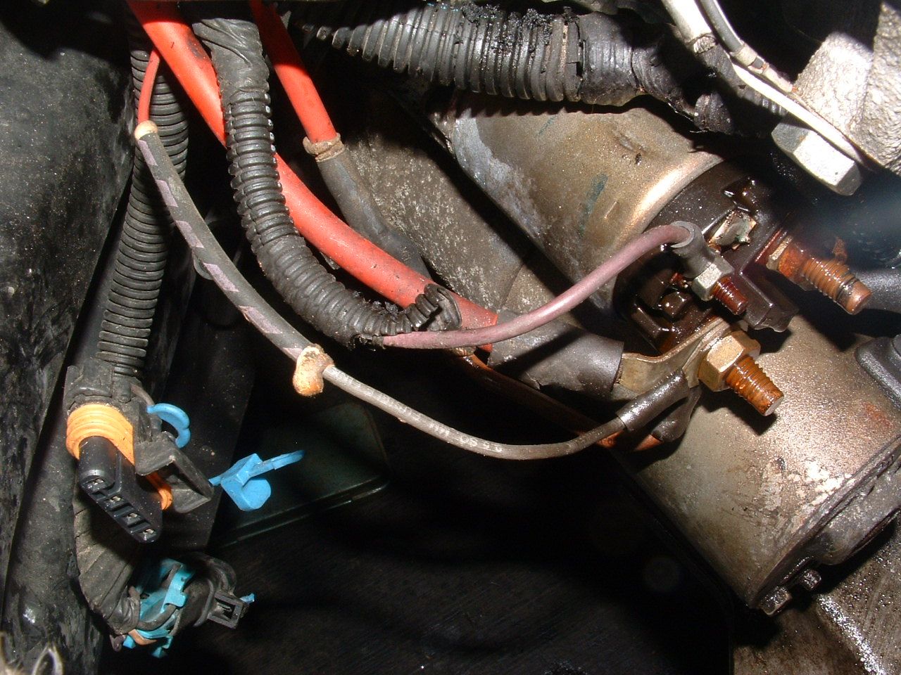
The fuse links are attached to the wires near the solenoid. Follow the wire back and you will see a heat shrinked covering with a hard sealer inside. Usually the wire changes color from one end of the link to the other You can see one in this picture:
The one RED wire goes thru the link and turns into a grey colored wire. You can almost see the other one on the red wire that goes to the alternator on the side closest to the block.
BC
The one RED wire goes thru the link and turns into a grey colored wire. You can almost see the other one on the red wire that goes to the alternator on the side closest to the block.
BC
Last edited by Bill Curlee; 07-28-2016 at 03:44 PM.
07-28-2016, 04:22 PM
#14
Tech Contributor
Member Since: Dec 1999
Location: Anthony TX
Posts: 32,736
Received 2,180 Likes
on
1,583 Posts
CI 6,7,8,9,11 Vet
St. Jude Donor '08
[QUOTE=8VETTE7;1592726584]
Fuseable links are toward the end of the cables where they attach to the solenoid. You should have noticed a bit if a bulge on the wire just before the lug on the end of the wire. Those are the fuseable links.
Testing the continuity of the wires can be done with the cables still in the wire harness. Connect a piece of known good wire to the lug of one of the red wires, disconnect the wire from the alternator and then use an ohm meter to measure the resistance of the two individual red wires. Should be very near zero ohms. If not then you need to determine why there is resistance...........
Should have known BC would have a picture!!!!
LMAO... I try hard to have the right ones brother!
Bill
07-28-2016, 04:47 PM
#15
Le Mans Master
07-28-2016, 10:54 PM
#16
Drifting


In post #3 you said "as I was checking things out the plastic under the connection leads appears to move while trying to remove nut on connections". What was the condition of that connection when you took it off and cleaned the corrosion. If it is loose at all that could be your problem. I know you said you cleaned and reinstalled tight but make sure those posts going into the solenoid are rock solid.
07-29-2016, 08:46 AM
#17
The fuse links are attached to the wires near the solenoid. Follow the wire back and you will see a heat shrinked covering with a hard sealer inside. Usually the wire changes color from one end of the link to the other You can see one in this picture:
The one RED wire goes thru the link and turns into a grey colored wire. You can almost see the other one on the red wire that goes to the alternator on the side closest to the block.
BC
The one RED wire goes thru the link and turns into a grey colored wire. You can almost see the other one on the red wire that goes to the alternator on the side closest to the block.
BC
07-29-2016, 10:21 AM
#18
1/4 mile/AutoX
07-29-2016, 10:28 AM
#19
Tech Contributor
Member Since: Dec 1999
Location: Anthony TX
Posts: 32,736
Received 2,180 Likes
on
1,583 Posts
CI 6,7,8,9,11 Vet
St. Jude Donor '08
The only 100% positive method of seeing if its good or not is to measure continuity of the wire with an OHM METER!
YES,,, If the fuse link is not solid and firm, IT MOST LIKELY is defectife. Please refer to that above (BOLD) provided statement!!
NOTE
The eyelets on the solenoid terminal look nasty (GREEN/corroded). Recommend removing and cleaning and properly retightening.
Hey, While it removed, use an OHM METER and check the continuity of that wire.

BC
YES,,, If the fuse link is not solid and firm, IT MOST LIKELY is defectife. Please refer to that above (BOLD) provided statement!!
NOTE
The eyelets on the solenoid terminal look nasty (GREEN/corroded). Recommend removing and cleaning and properly retightening.
Hey, While it removed, use an OHM METER and check the continuity of that wire.
BC
07-29-2016, 10:53 AM
#20
The only 100% positive method of seeing if its good or not is to measure continuity of the wire with an OHM METER!
YES,,, If the fuse link is not solid and firm, IT MOST LIKELY is defectife. Please refer to that above (BOLD) provided statement!!
NOTE
The eyelets on the solenoid terminal look nasty (GREEN/corroded). Recommend removing and cleaning and properly retightening.
Hey, While it removed, use an OHM METER and check the continuity of that wire.
BC