When you click on links to various merchants on this site and make a purchase, this can result in this site earning a commission. Affiliate programs and affiliations include, but are not limited to, the eBay Partner Network.
I wanted to try and contribute something to the forum so here it goes
This is a basic soldering and wire connections walk thru
1. Disconnect your battery/batteries
This is for your safety and so you do not damage any thing. After all I don't think any of us are certified in 12 volt wielding
2. Inspect the wire you want to repair
If there is any corrosion or the wire does not look like fresh shiny copper cut it back until it does. If you do not start with clean corrosion free wire you are just asking for trouble and future headaches.
3. Be prepared
Have all your tools and what ever you need ready soldering is a meticulous task so there is no need to make it worse
4. Repair time
Now that we are ready now to perform the repair slip your heat shrink down one of the wires once you solder them you can't put it on. Now you can strip your wire casing back and connect the 2 pieces together. There are a couple ways you can put them together you can twist them like a bread tie, make both ends into j hooks and then squeeze them down , or mesh the wire together which I never have luck with because the strands usually bunch up and make a mess. What ever way you choose is irrelevant as long as the solder joint is good. Now get out your soldering iron and heat the wire from underneath. Do not heat the wire from the top. Once the wires start to warm up apply some flux to the bare copper it will clean and prep the wire for the solder. Now take your solder and push down on the wire lightly. What you are doing here is helping the heat transfer thru the iron to the wire. When the wire gets hot enough the solder will begin to melt. The solder should flow through the wire strands and encase all the exposed copper. it is really hard to over apply solder as it will just drip away when the wire is saturated but if the repair is near a flex/stress point try not to get carried away with because the solder can wick beyond the exposed copper. Solder wicking is not good as it will make the wire rigid in that area and can cause future failure if it can not flex enough. Do not melt the solder on the iron to speed the process this will produce what is called a cold solder and will have high resistance be weak and essentially will be worthless.
Now that you have solders the wire let it cool this should not take long and inspect your repair. The solder should cover all of the exposed wire and be evenly dispersed. Note if you have your wire heated properly like instructed above you can apply the solder all in one spot and it will disperse itself throughout the wire. With that said if you are having trouble with the solder flowing chances are that you don't have enough heat in the wire. So now that you have a good looking solder joint with enough solder in it to properly conduct electricity you need to check the strength of the joint. Always pull test your joint and be fairly aggressive with this because it is easier to fix it now than later.
After inspection has passed you need to seal your solder joint the best way to do this is with heat shrink. There are 2 types of heat shrink. One is just that heat shrink and the other is self sealing heat shrink that has glue inside. Both of these are sufficient but If you do not have self sealing you need to apply a small amount of dielectric tune up grease to the solder to protect it before using the heat shrink. Then heat up the heat shrink until it has shrunk down and tightly wrapped around the wire.
Now I have a couple pics to show what all we have gone over
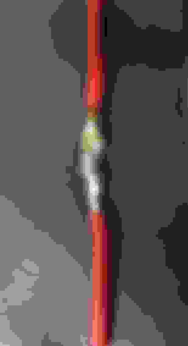
This is what you want to see look how the solder looks like it was liquid and absorbed itself in to the wire. Also note that all the copper is covered by the solder.
This is just a second example of a proper solder joint.
This is a prime example of who you must examine your work. From the top this joint looked flawless but when you look at the bottom side there was not enough solder applied. This connection could potentially be weak have excessive resistance and be prone to corrosion
This is what a cold solder joint looks like you can see how it looks like the solder is sitting on top of the wire and did not absorb in. This joint will not conduct properly has high resistance and will break apart at the first sign of movement.
Look at the heat shrink it was heated evenly and thoroughly without burning. Make shure you completely shrink the tube to seal out contamination and prevent corrosion. This heat shrink does NOT have the sealer built in it is sufficient but I only use it if there is no other option.
This heat shrink has the sealer inside note how it was heated until the glue was started to squeeze out at the ends this is what you want.
Here are some connectors the top one is a heat shrink connection and the bottom two are not. Please avoid the non heat shrink connections they will not seal out contamination allowing corrosion to form and causing future problems.
ring terminals come in two basic styles the top one is what you want see how the end is closed off compared to the lower one where the wire will be left exposed. When at all possible use the terminals that will seal off the wire end to prevent corrosion. Now these both do not have heat shrink on them so don't forget to put some on the wire before you crimp the terminal on.
This is a picture of a properly crimped and heated but connection. Note you want the wire to bottom out in the connector for the best connection. When you use these you want to crimp the connection with the right tool so you do not puncture the heat shrink. When crimping you want to make shure that you squeeze it down really tight ( if you can pull it apart it was not crimped enough) but do not squeeze so tight that you damage the heat shrink. Then heat it up with your heat gun and seal it up.
On this tool you can see that it is designed for both heat shrink and non heat shrink connectors. You really want to follow the rules here so you do not damage your heat shrink making it useless.
Another thing to add is get some isopropyl alcohol, and some acid brushes and clean off the flux residue left on your solder connections before you heat shrink it, as over time it can break down the solder. I was a micro solder tech in the USN for 8 yrs, and that was one of the key things they trained us to do after you completed the repair.
Another thing to add is get some isopropyl alcohol, and some acid brushes and clean off the flux residue left on your sold connections before you heat shrink it, as over time it can break down the solder. I was a micro sold tech in the USN for 8 yrs, and that was one of the key things they trained us to do after you completed the repair.
Thanks that was something that was never taught to me.
I saw this old thread and thought that if I'll bump it, it won't be a big crime. Because these advices are useful. BTW, where can I find more information about soldering and welding? I mean, not just any information but reliable one.
To learn more I would suggest YouTube to start but don’t just watch any channel. I usually stick to channels that are from learning facilities that have a proven track record in that subject. Solder in most cases is easily self taught with a little guidance because you can easily diagnose problems visually. Welding on the other hand is much more complex and still can be visually diagnosed for the most part but that does not mean all ugly welds are weak and all pretty welds are strong.

 08-03-2016, 11:27 PM