
Need help with CEL code
 10-07-2011, 09:57 AM
#1
Intermediate

Thread Starter

Member Since: Mar 2011
Location: Park hills MO
Posts: 43
Likes: 0
Received 0 Likes
on
0 Posts
I was driving home yesterday and my CEL came on, when I got home I put the hp tuners on it and it read code P0608 which I know is the VSS output circuit. My problem is this. I don't know where to start to fix this issue. I've read tons of threads last night bit none of these address my situation and I need your help.
Thanks
Kory
Thanks
Kory
 10-07-2011, 09:59 AM
#2
Intermediate
Thread Starter
Member Since: Mar 2011
Location: Park hills MO
Posts: 43
Likes: 0
Received 0 Likes
on
0 Posts
I was driving home yesterday and my CEL came on, when I got home I put the hp tuners on it and it read code P0608 which I know is the VSS output circuit. My problem is this. I don't know where to start to fix this issue. I've read tons of threads last night bit none of these address my situation and I need your help.
Thanks
Kory
Thanks
Kory
10-07-2011, 11:41 AM
#3
Team Owner


Looks like it could be a problem with a ground, a problem with the connector at the ECM (or with the ECM) or a problem with the connector at the Instrument panel (IPC) or the IPC itself.
Here is the service manual information on the P0608
DTC P0608
Circuit Description
The engine control module (ECM) creates the vehicle speed output signal by pulsing the circuit to ground. The ECM monitors the voltage on the vehicle speed output circuit. If the ECM determines that the voltage is out of the normal operating range, a DTC sets.
DTC Descriptor
This diagnostic procedure supports the following DTC:
DTC P0608 Vehicle Speed Output Circuit
Conditions for Running the DTC
� The engine speed is more than 400 RPM.
� The ignition voltage is between 6-18 volts.
Conditions for Setting the DTC
� The ECM detects that the commanded state of the driver and the actual state of the signal circuit do not match.
� The above condition must be present for a minimum of 5 seconds.
Action Taken When the DTC Sets
The ECM records the operating conditions at the time the diagnostic fails. The ECM displays the failure information in the Failure Records on the scan tool.
Conditions for Clearing the MIL/DTC
� The history DTC clears after 40 malfunction free warm-up cycles.
� The DTC becomes history when the conditions for setting the DTC are no longer present.
� The powertrain control module (PCM) receives the clear code command from the scan tool.
Step
Action
Yes
No
Schematic Reference: Instrument Cluster Schematics
1
Did you perform the Diagnostic System Check - Vehicle?
Go to Step 2
Go to Diagnostic System Check - Vehicle in Vehicle DTC Information
2
Install a scan tool.
Raise the vehicles drive wheels. Refer to Lifting and Jacking the Vehicle in General Information.
Start the engine.
Place the transmission into drive.
With the scan tool, observe the Vehicle Speed parameter in the engine control module (ECM) Engine Data 2 data list.
Does the Vehicle Speed parameter match the speedometer display?
Go to Testing for Intermittent Conditions and Poor Connections in Wiring Systems
Go to Step 3
3
Turn OFF the ignition.
Disconnect the ECM connector C1.
Install one lead of the J 33431-C Signal Generator and Instrument Panel Tester to the vehicle speed signal circuit at the ECM harness connector, and the other lead to a good ground.
Turn ON the ignition, with the engine OFF.
Set the J 33431-C to generate a speedometer signal.
Does the vehicle speedometer indicate approximately 55 MPH?
Go to Step 5
Go to Step 4
4
Test the vehicle speed signal circuit for the following:
� An open
� A short to voltage
� A short to ground
Refer to Circuit Testing and to Wiring Repairs in Wiring Systems.
Did you find and correct the condition?
Go to Step 9
Go to Step 6
5
Inspect for poor connections at harness connector of the ECM. Refer to Testing for Intermittent Conditions and Poor Connections and to Connector Repairs in Wiring Systems.
Did you find and correct the condition?
Go to Step 9
Go to Step 7
6
Inspect for poor connections at the harness connector of the instrument panel cluster (IPC). Refer to Testing for Intermittent Conditions and Poor Connections and to Connector Repairs in Wiring Systems.
Did you find and correct the condition?
Go to Step 9
Go to Step 8
7
Replace the ECM. Refer to Control Module References in Computer/Integrating Systems for replacement, setup, and programming.
Did you complete the replacement?
Go to Step 9
--
8
Replace the IPC. Refer to Control Module References in Computer/Integrating Systems for replacement, setup, and programming.
Did you complete the replacement?
Go to Step 9
--
9
Use the scan tool in order to clear the DTCs.
Operate vehicle within the Conditions for Running this DTC.
Does the DTC reset?
Go to Step 2
System OK
10-07-2011, 12:06 PM
#4
Intermediate
Thread Starter
Member Since: Mar 2011
Location: Park hills MO
Posts: 43
Likes: 0
Received 0 Likes
on
0 Posts
I also want to add this to my issue. Before the Cel came on I had the car idling and I pulled off a plug wire not thinking about it shocking me and of course it did so I let go of the wire because I was getting shocked and the plug wire came to rest onto the fuse box on the passenger side. The car died so I put the plug wire back on started it up and drove off. Then the Cel came on and no speedo. I think I may have fried something when the plug wire touched something on the car.
10-07-2011, 12:10 PM
#5
Race Director


I also want to add this to my issue. Before the Cel came on I had the car idling and I pulled off a plug wire not thinking about it shocking me and of course it did so I let go of the wire because I was getting shocked and the plug wire came to rest onto the fuse box on the passenger side. The car died so I put the plug wire back on started it up and drove off. Then the Cel came on and no speedo. I think I may have fried something when the plug wire touched something on the car.
10-07-2011, 01:05 PM
#6
Team Owner
I also want to add this to my issue. Before the Cel came on I had the car idling and I pulled off a plug wire not thinking about it shocking me and of course it did so I let go of the wire because I was getting shocked and the plug wire came to rest onto the fuse box on the passenger side. The car died so I put the plug wire back on started it up and drove off. Then the Cel came on and no speedo. I think I may have fried something when the plug wire touched something on the car.
 You can pretty much disregard my diagnostics above.
Last edited by talon90; 10-07-2011 at 01:23 PM.
10-07-2011, 01:50 PM
#7
Intermediate
Thread Starter
Member Since: Mar 2011
Location: Park hills MO
Posts: 43
Likes: 0
Received 0 Likes
on
0 Posts
Well with that little issue that I forgot to mention, what part do u think is fried? After further looking I see that my Odometer isn't working either. Damnit. Stupid mistake I made by taking off that plug wire.
10-07-2011, 02:49 PM
#8
Instructor

Member Since: Jun 2011
Location: Clayton North Carolina
Posts: 238
Likes: 0
Received 1 Like
on
1 Post
bigbonder, sorry for your troubles but I would probably check every fuse in the fuse box and while your at it see if you notice anywhere around the area that looks discolored possibly from the spark. Also, you already learned this lesson but just remember not to handle those live plug wires in the future.
 10-07-2011, 03:41 PM
#9
Tech Contributor
Member Since: Oct 1999
Location: Charlotte, NC (formerly Endicott, NY)
Posts: 40,089
Received 8,928 Likes
on
5,333 Posts

You may have fried something in the Instrument Cluster or the ECM.
The diagnostic procedure shown above is from the 05 Service Manual. In subsequent manuals they have a different procedure which may not provide any different results but the procedure is different.
Here is the procedure from the 08 Service Manual:
DTC B0608: Vehicle Speed Output Circuit

Circuit/System Description
The engine control module (ECM) creates the vehicle speed output signal by pulsing the circuit to ground at a rate of 4KPPM. The vehicle speed sensor (VSS) input is pulled high to B+ in the instrument panel cluster (IPC). The IPC converts the 4KPPM vehicle speed signal to a speedometer position to indicate the vehicle speed. The ECM monitors the voltage at the vehicle speed output signal circuit to determine when the voltage is out of the normal operating range.
Conditions for Running the DTC
• The engine speed is more than 400 RPM.
• The ignition voltage is between 9-18 volts.
Conditions for Setting the DTC
• The ECM detects that the commanded state of the driver and the actual state of the signal circuit do not match.
• The above condition must be present for a minimum of 5 seconds.
Action Taken When the DTC Sets
The ECM records the operating conditions at the time the diagnostic fails. The ECM displays the failure information in the Failure Records on the scan tool.
Conditions for Clearing the DTC
• The DTC becomes history when the conditions for setting the DTC are no longer present.
• The history DTC clears after 40 malfunction-free warm-up cycles.
Reference Information
Schematic Reference
Instrument Cluster Schematics
Connector End View Reference
Component Connector End Views
Description and Operation
Instrument Cluster Description and Operation
Circuit/System Verification
Start the engine with the scan tool installed, the vehicle drive wheels raised and the transmission placed in drive or the first gear. Refer to Lifting and Jacking the Vehicle. Verify that the speedometer display matches the scan tool Vehicle Speed parameter in the ECM Engine Data List.
Circuit/System Testing
Important: The drive wheels of the vehicle must be raised and the transmission must be placed in drive or first gear. Refer to Lifting and Jacking the Vehicle.
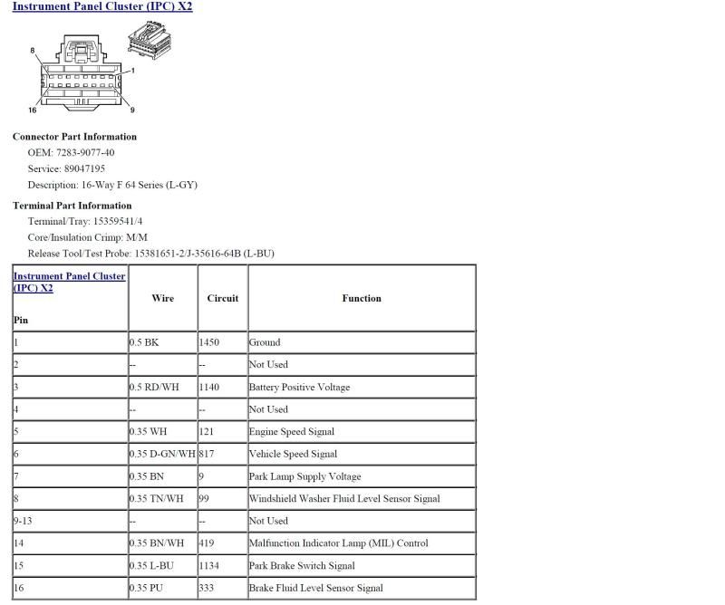
1. Ignition OFF, disconnect the X2 harness connector at the radio.
2. Start the engine, with the drive wheels raised and the vehicle placed in drive or the first gear. Verify that the speedometer value does not match the scan tool Vehicle Speed parameter in the ECM Engine Data List.
⇒If the speedometer matches the scan tool Vehicle Speed parameter, test the vehicle speed signal circuit terminal D for a short to voltage, a short to ground or an open/high resistance. If circuit tests normal, replace the radio.
3. Ignition OFF, disconnect the harness connector at the head-up display (HUD).
4. Start the engine, with the drive wheels raised and the vehicle placed in drive or the first gear. Verify that the speedometer value does not match the scan tool Vehicle Speed parameter in the ECM Engine Data List.
⇒If the speedometer matches the scan tool Vehicle Speed parameter, test the vehicle speed signal circuit terminal 3 for a short to voltage, a short to ground or an open/high resistance. If circuit tests normal, replace the HUD.
5. Ignition OFF disconnect the X1 harness connector at the engine control module.
6. Ignition ON, test for 9-11 volts between the vehicle speed signal circuit terminal 57 and ground.
⇒If less than 9 volts, test the signal circuit for a short to ground or an open/high resistance. If the circuit tests normal, replace the IPC.
⇒If greater than 11 volts, test the signal circuit for a short to voltage. If the circuit tests normal, replace the IPC.
7. If all circuits test normal, test or replace the ECM.
Repair Instructions
Perform the Diagnostic Repair Verification after completing the diagnostic procedure.
Control Module References for the ECM, IPC, HUD and radio replacement, setup and programming
Bill
The diagnostic procedure shown above is from the 05 Service Manual. In subsequent manuals they have a different procedure which may not provide any different results but the procedure is different.
Here is the procedure from the 08 Service Manual:
DTC B0608: Vehicle Speed Output Circuit
Circuit/System Description
The engine control module (ECM) creates the vehicle speed output signal by pulsing the circuit to ground at a rate of 4KPPM. The vehicle speed sensor (VSS) input is pulled high to B+ in the instrument panel cluster (IPC). The IPC converts the 4KPPM vehicle speed signal to a speedometer position to indicate the vehicle speed. The ECM monitors the voltage at the vehicle speed output signal circuit to determine when the voltage is out of the normal operating range.
Conditions for Running the DTC
• The engine speed is more than 400 RPM.
• The ignition voltage is between 9-18 volts.
Conditions for Setting the DTC
• The ECM detects that the commanded state of the driver and the actual state of the signal circuit do not match.
• The above condition must be present for a minimum of 5 seconds.
Action Taken When the DTC Sets
The ECM records the operating conditions at the time the diagnostic fails. The ECM displays the failure information in the Failure Records on the scan tool.
Conditions for Clearing the DTC
• The DTC becomes history when the conditions for setting the DTC are no longer present.
• The history DTC clears after 40 malfunction-free warm-up cycles.
Reference Information
Schematic Reference
Instrument Cluster Schematics
Connector End View Reference
Component Connector End Views
Description and Operation
Instrument Cluster Description and Operation
Circuit/System Verification
Start the engine with the scan tool installed, the vehicle drive wheels raised and the transmission placed in drive or the first gear. Refer to Lifting and Jacking the Vehicle. Verify that the speedometer display matches the scan tool Vehicle Speed parameter in the ECM Engine Data List.
Circuit/System Testing
Important: The drive wheels of the vehicle must be raised and the transmission must be placed in drive or first gear. Refer to Lifting and Jacking the Vehicle.
1. Ignition OFF, disconnect the X2 harness connector at the radio.
2. Start the engine, with the drive wheels raised and the vehicle placed in drive or the first gear. Verify that the speedometer value does not match the scan tool Vehicle Speed parameter in the ECM Engine Data List.
⇒If the speedometer matches the scan tool Vehicle Speed parameter, test the vehicle speed signal circuit terminal D for a short to voltage, a short to ground or an open/high resistance. If circuit tests normal, replace the radio.
3. Ignition OFF, disconnect the harness connector at the head-up display (HUD).
4. Start the engine, with the drive wheels raised and the vehicle placed in drive or the first gear. Verify that the speedometer value does not match the scan tool Vehicle Speed parameter in the ECM Engine Data List.
⇒If the speedometer matches the scan tool Vehicle Speed parameter, test the vehicle speed signal circuit terminal 3 for a short to voltage, a short to ground or an open/high resistance. If circuit tests normal, replace the HUD.
5. Ignition OFF disconnect the X1 harness connector at the engine control module.
6. Ignition ON, test for 9-11 volts between the vehicle speed signal circuit terminal 57 and ground.
⇒If less than 9 volts, test the signal circuit for a short to ground or an open/high resistance. If the circuit tests normal, replace the IPC.
⇒If greater than 11 volts, test the signal circuit for a short to voltage. If the circuit tests normal, replace the IPC.
7. If all circuits test normal, test or replace the ECM.
Repair Instructions
Perform the Diagnostic Repair Verification after completing the diagnostic procedure.
Control Module References for the ECM, IPC, HUD and radio replacement, setup and programming
Bill
Last edited by Bill Dearborn; 10-07-2011 at 03:48 PM.
10-07-2011, 04:09 PM
#10
Intermediate
Thread Starter
Member Since: Mar 2011
Location: Park hills MO
Posts: 43
Likes: 0
Received 0 Likes
on
0 Posts
Thanks bill. A silly question I'm sure but how do I test the vehicle for a short to voltage or a short to ground or an open/high resistance ? Not the best at implementing what I read
10-07-2011, 05:26 PM
#11
Tech Contributor
Member Since: Oct 1999
Location: Charlotte, NC (formerly Endicott, NY)
Posts: 40,089
Received 8,928 Likes
on
5,333 Posts
In a car you are going to have circuits that provide 12V or Ground to a component. These are used to power the component. The component will also have signal input and output circuits which can be shorted to either the power or ground inputs through some sort of failure. Checking for shorts to voltage or ground is nothing but using the DVM to measure those signal circuits for those conditions.
Resistance can be anywhere from 0 to infinity. Zero represents a short and infinity represents an open. Depending on what you are expecting to see you can have resistive shorts to ground or voltage where you are expecting to see infinity but read some value less than infinity. In addition, with shorts to voltage you may see a voltage where you don't expect to see one.
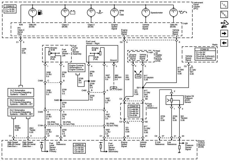
If you look at the schematic for the VSS signal (Circuit 817) that goes from the ECM to the IPC you can see it goes from the ECM to the fuse block in the engine compartment. From there it is distributed to the HUD, IPC and the Radio. Depending on where the high voltage from the spark plug hit and which point may have failed first you could have screwed up the ECM, IPC, HUD or Radio or all 4. None of those items like to be exposed to any voltage above the 12-15 V range and the spark runs in the range of 17K to 40K volts so you have a huge potential for electrical overstress in all of those modules. I doubt the wiring would have blown since it would have taken a higher current for a longer duration to have melted the wires but contacts in various connectors could have been damaged. All of that has to be checked out.
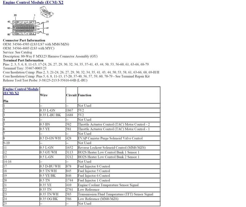
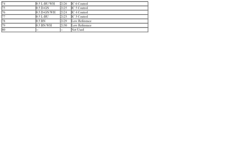
ECM X2 Cont'd
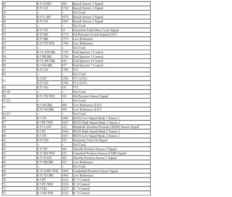
ECM X2 Cont'd
Not sure why this happened as the fuse box cover should have kept the spark wire from getting in.
This is all simple stuff to do but it will be time consuming as you will have to get access to all of the connectors to do the checks so there will be a fair amount of dis-assembly required.
The VSS signal to the radio is located in Connector X2 on the radio. One way to check to see if it is still working is to check your speed controlled volume. If that isn't working along with the IPC and HUD not working the most likely suspect will be the ECM as it is hopefully unlikely all of them would have failed at once.
Bill
Last edited by Bill Dearborn; 10-07-2011 at 05:36 PM.
10-07-2011, 05:49 PM
#12
Intermediate
Thread Starter
Member Since: Mar 2011
Location: Park hills MO
Posts: 43
Likes: 0
Received 0 Likes
on
0 Posts
Bill I want to say thanks for your knowledge and your willingness to help me out. I am going to dive into it some this weekend. I will report back with any information that I find out . Thanks again.

