
C6 Rear Suspension Geometry lesson sought
 10-25-2007, 01:52 AM
#1
Le Mans Master

Thread Starter
I'm wanting to settle my confusion over the current generation's rear suspension, and would like for someone who's got a solid handle on it to 'splain it to me. From the illustrations and photos I've seen, I can't figure out how the C6 manages to avoid or to deal with the apparent issue of positive camber gain in roll at the outside rear tire, unless jacking or some other issue(s) are perhaps taking precedence. And, what's up with the IC's being on the "wrong" side of the wheel centerline? Is there a component link I'm not taking into account? I'm at a loss here, so any insight as to what's going on with this specific suspension layout would be greatly appreciated. Maybe I'm just misinterpreting what I'm looking at...
Thanks, in advance.

Thanks, in advance.
 10-25-2007, 02:58 AM
#2
Burning Brakes

Member Since: Mar 2006
Location: SF Bay CA
Posts: 906
Likes: 0
Received 0 Likes
on
0 Posts

I'm wanting to settle my confusion over the current generation's rear suspension, and would like for someone who's got a solid handle on it to 'splain it to me. From the illustrations and photos I've seen, I can't figure out how the C6 manages to avoid or to deal with the apparent issue of positive camber gain in roll at the outside rear tire, unless jacking or some other issue(s) are perhaps taking precedence. And, what's up with the IC's being on the "wrong" side of the wheel centerline? Is there a component link I'm not taking into account? I'm at a loss here, so any insight as to what's going on with this specific suspension layout would be greatly appreciated. Maybe I'm just misinterpreting what I'm looking at...
Thanks, in advance.
Thanks, in advance.
 10-25-2007, 10:50 AM
#3
Safety Car

Negative camber gain is beneficial for handling. If you're a cruiser or Drag Racer, not so important. Camber is the lateral tilt of the suspension (and hence the wheel and the tire) to the road surface. Proper camber (along with toe and caster) make sure that the tire tread surface is as flat as possible on the road surface. Variable camber through geometry and a short arm/long arm design allow this.The problem with regular fixed-geometry suspension is that the camber is set up to be ideal when driving straight. This means that however much you dislike the idea (Mustang owners!), when you corner, less of the tire's tread is in contact with the road surface because the tyre has to tilt slightly when the steering is turned. Corvette owners who Zero out Camber for tire wear are doing it at the expense of handling and traction while turning. Camber change as a suspension compresses in turns keeps the tire flat for best traction. That said, camber specs are a compromise between Handling, tire wear, and traction. Pick your poison. You'll notice that Road course cars typically have lots of negative camber.
More suspension General info here:
http://www.carbibles.com/suspension_bible.html

More suspension General info here:
http://www.carbibles.com/suspension_bible.html
Last edited by Modshack; 10-25-2007 at 03:41 PM.
10-25-2007, 12:59 PM
#4
Team Owner

Member Since: Sep 2003
Location: Raleigh / Rolesville NC
Posts: 43,084
Likes: 0
Received 23 Likes
on
23 Posts

alignment
for aggressive street driving or occasional road track driving
front
-1.5* to -1.25* camber
Max but equal caster
Tow 0 ( zero ) to 1/32" OUT
rear
-1.0* to -.75* camber ( 1/2 of front)
Tow 1/32" to 1/16" IN
numbers must be exact no ranges
So when the tires have NEGATIVE camber, and the car is turning a reasonable sharp corner more the contact patch of the out side tires will be on the road.
If the alignment is set up as neutral, that turn will make the outside tires fold under or become POSITIVE camber.
The only place positive camber is needed is on the inside tires of NASCAR cars and trucks
10-25-2007, 01:00 PM
#5
Racer


Member Since: Jun 2005
Location: Mine Hill New Jersey
Posts: 307
Likes: 0
Received 0 Likes
on
0 Posts
The Corvette has negative camber gain as the suspension compresses, and positive as it extends. That's exactly what is required in a handling suspension car. This is accomplished as stated above because of the unequal length control arms. What is the problem?
10-25-2007, 02:22 PM
#6
Burning Brakes
Member Since: Mar 2006
Location: SF Bay CA
Posts: 906
Likes: 0
Received 0 Likes
on
0 Posts
Positive camber gain is beneficial for handling. If you're a cruiser or Drag Racer, not so important. Camber is the lateral tilt of the suspension (and hence the wheel and the tire) to the road surface. Proper camber (along with toe and caster) make sure that the tire tread surface is as flat as possible on the road surface. Variable camber through geometry and a short arm/long arm design allow this.The problem with regular fixed-geometry suspension is that the camber is set up to be ideal when driving straight. This means that however much you dislike the idea (Mustang owners!), when you corner, less of the tire's tread is in contact with the road surface because the tyre has to tilt slightly when the steering is turned. Corvette owners who Zero out Camber for tire wear are doing it at the expense of handling and traction while turning. Camber change as a suspension compresses in turns keeps the tire flat for best traction. That said, camber specs are a compromise between Handling, tire wear, and traction. Pick your poison. You'll notice that Road course cars typically have lots of negative camber.
More suspension General info here:
http://www.carbibles.com/suspension_bible.html
More suspension General info here:
http://www.carbibles.com/suspension_bible.html
 10-25-2007, 02:26 PM
#7
Le Mans Master
Thread Starter
I appreciate the replies, but I guess I should have stated at the outset that I have a good understanding of basic suspension fundamentals, and know a fair amount about how different arrangements effect camber gain, bump steer, roll-oversteer and such. It's OK, no offense taken, but I've drag raced and road raced off and on since the late '70's, and first started tinkering with suspension mods on Corvettes and other GM's in the early '80's, so I'm not exactly a newbie asking for the 101 here.
It's my grasp of what I do understand that has me perplexed about the pic below...
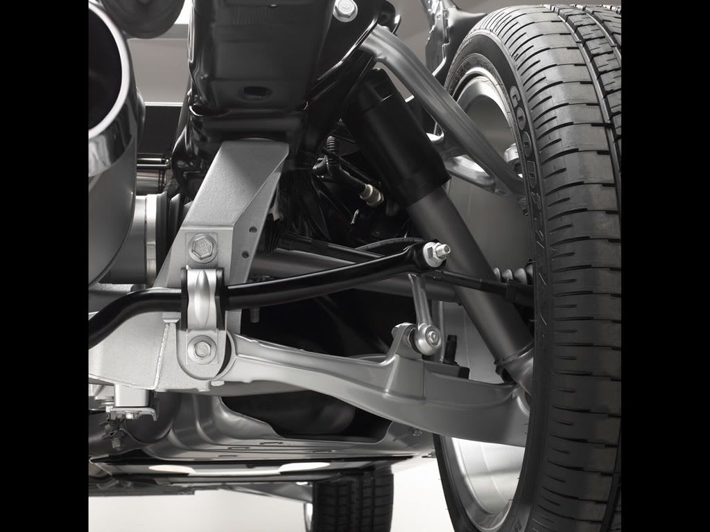
In it, you can see that the short upper arm is at such an angle relative to the long lower arm that the instantaneous center of this layout puts the effective swing arm radius on the wrong side of the wheel center line for negative camber gain to result. I was so taken aback by this that I took the time to scale up paper dolls (poor man's suspension computer) of this geometry, and was amazed at just how badly it appears to function.
So, I guess what I'm really asking is, "what's wrong with this picture?" If I had access to a C6, maybe I would see what I've missed and it would make sense. However, I don't, and I'm relying on you guys to point it out. Perhaps someone could share a better pic or graphic that shows this arrangement better and this little mystery would go away. Maybe it's all just an effect of the wide angle lense... (??)
Thanks, again.
BTW, not trying to flame anyone, but other than in books and designs from before the modern era, I haven't seen a case made for positive camber gain being a good thing for the outside tire patch, and it was a characteristic we never sought to induce in the formula cars I've driven...
It's my grasp of what I do understand that has me perplexed about the pic below...
In it, you can see that the short upper arm is at such an angle relative to the long lower arm that the instantaneous center of this layout puts the effective swing arm radius on the wrong side of the wheel center line for negative camber gain to result. I was so taken aback by this that I took the time to scale up paper dolls (poor man's suspension computer) of this geometry, and was amazed at just how badly it appears to function.
So, I guess what I'm really asking is, "what's wrong with this picture?" If I had access to a C6, maybe I would see what I've missed and it would make sense. However, I don't, and I'm relying on you guys to point it out. Perhaps someone could share a better pic or graphic that shows this arrangement better and this little mystery would go away. Maybe it's all just an effect of the wide angle lense... (??)
Thanks, again.
BTW, not trying to flame anyone, but other than in books and designs from before the modern era, I haven't seen a case made for positive camber gain being a good thing for the outside tire patch, and it was a characteristic we never sought to induce in the formula cars I've driven...
Last edited by TheSkunkWorks; 10-25-2007 at 02:30 PM.
10-25-2007, 02:35 PM
#8
Racer
Member Since: Jun 2005
Location: Mine Hill New Jersey
Posts: 307
Likes: 0
Received 0 Likes
on
0 Posts
BTW, not trying to flame anyone, but other than in books and designs from before the modern era, I haven't seen a case made for positive camber gain being a good thing for the outside tire patch, and it was a characteristic we never sought to induce in the formula cars I've driven...
10-25-2007, 02:44 PM
#9
Le Mans Master
Thread Starter
10-25-2007, 02:48 PM
#10
Burning Brakes
Member Since: Mar 2006
Location: SF Bay CA
Posts: 906
Likes: 0
Received 0 Likes
on
0 Posts
BTW, not trying to flame anyone, but other than in books and designs from before the modern era, I haven't seen a case made for positive camber gain being a good thing for the outside tire patch, and it was a characteristic we never sought to induce in the formula cars I've driven...

Anyhow, thanks for the pic, I see what you are talking about now, and yes it would seem I dont see any negative gain there at first glance, Im going to jack up my car and move the rear by hand and see what kind of results I get
10-25-2007, 03:00 PM
#11
Le Mans Master
Thread Starter
Invisiguard, you ought to see the debates over the "virtues" of DragVette's 6-link (with parallel links and IC's at infinity) for auto-Xing over in C3. 
Let me know what you find. This is very puzzling...
Let me know what you find. This is very puzzling...
10-25-2007, 03:05 PM
#12
Drifting


In it, you can see that the short upper arm is at such an angle relative to the long lower arm that the instantaneous center of this layout puts the effective swing arm radius on the wrong side of the wheel center line for negative camber gain to result. I was so taken aback by this that I took the time to scale up paper dolls (poor man's suspension computer) of this geometry, and was amazed at just how badly it appears to function.
So, I guess what I'm really asking is, "what's wrong with this picture?" If I had access to a C6, maybe I would see what I've missed and it would make sense. However, I don't, and I'm relying on you guys to point it out. Perhaps someone could share a better pic or graphic that shows this arrangement better and this little mystery would go away. Maybe it's all just an effect of the wide angle lense... (??)
Thanks, again.
BTW, not trying to flame anyone, but other than in books and designs from before the modern era, I haven't seen a case made for positive camber gain being a good thing for the outside tire patch, and it was a characteristic we never sought to induce in the formula cars I've driven...
Lower A-arm bolts measured to the outside are 10"F & 7"R high off the ground (producing anti-dive, I think) and center of ball joint is at 6.5" or so. I didn't take the wheels off.
Upper A-arm bolts measured to the outside are 19.5"F & 19.5"R with the center of the ball joint at 19.5" as well.
Again, this is approximate and on my car so ... deduce away. I don't know enough about the relationships to say much. But, I hope this helps to answer your questions as the photo does make the angle look extreme
--Dan
Last edited by dbratten; 10-25-2007 at 03:08 PM. Reason: clarify height reference point for measurements
10-25-2007, 03:10 PM
#13
Le Mans Master
Thread Starter
Thanks Dan. Yes, that's anti-dive, or anti-squat might be a better term for the rear. That's a lot less angle than the pic portrays, and at which the SLA geometry can apparently do it's job.
Last edited by TheSkunkWorks; 10-25-2007 at 03:18 PM.
10-25-2007, 03:23 PM
#14
Le Mans Master
10-25-2007, 03:32 PM
#15
Le Mans Master
Thread Starter
I see what you're talking about in the posted picture. The first thing that strikes me is that it is a picture of a body-off chassis. That lower A-arm is at a fairly extreme angle downwards. I suspect that a fully loaded chassis puts the lower A-arms at a level position and therefore greatly reducing that angle on the upper one. Just my observation. I'm no expert.
Thanks, everyone who took the time to look into this. I believe my confusion was from nothing more than an optical illusion. Whew! That'll teach me to try math without proper sleep.

If anyone has any better pics or graphics, it would still be interesting to see.
10-25-2007, 03:40 PM
#16
Safety Car
I was fixated on the OP's reference to "Positive"
Last edited by Modshack; 10-25-2007 at 03:45 PM.
10-25-2007, 03:41 PM
#17
Burning Brakes
Member Since: Mar 2006
Location: SF Bay CA
Posts: 906
Likes: 0
Received 0 Likes
on
0 Posts
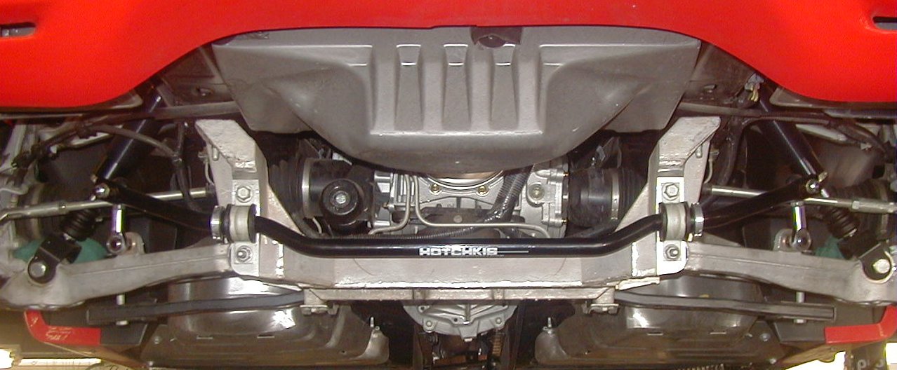
yeah I thought it might be drooping a bit too, heres a pic of a rear C5 suspension for comparison, indeed the lower arms are straightened out quite a bit more.
good discussion all around on this thread
good discussion all around on this thread
10-25-2007, 03:54 PM
#18
Safety Car
From the Suspension Bible link above..

Coil Spring type 1
This is a type of double-A or double wishbone suspension. The wheel spindles are supported by an upper and lower 'A' shaped arm. In this type, the lower arm carries most of the load. If you look head-on at this type of system, what you'll find is that it's a very parallelogram system that allows the spindles to travel vertically up and down. When they do this, they also have a slight side-to-side motion caused by the arc that the wishbones describe around their pivot points. This side-to-side motion is known as scrub. Unless the links are infinitely long the scrub motion is always present. There are two other types of motion of the wheel relative to the body when the suspension articulates. The first and most important is a toe angle (steer angle). The second is the camber angle, or lean angle. Steer and camber are the ones which wear tyres
Basically the alignment of the upper and lower pivot points will determine the Camber/toe change as the suspension articulates. I think use of the full droop shot a few posts up exagerates the effect (visually)
Last edited by Modshack; 10-25-2007 at 03:58 PM.
10-25-2007, 05:54 PM
#19

Having access to a C6, I went out and took some VERY rough measurements at installed loaded ride height on my 4-post lift. For reference, my wheel openings are at 26" F & 27" R off the ground.
Lower A-arm bolts measured to the outside are 10"F & 7"R high off the ground (producing anti-dive, I think) and center of ball joint is at 6.5" or so. I didn't take the wheels off.
Upper A-arm bolts measured to the outside are 19.5"F & 19.5"R with the center of the ball joint at 19.5" as well.
Again, this is approximate and on my car so ... deduce away. I don't know enough about the relationships to say much. But, I hope this helps to answer your questions as the photo does make the angle look extreme
--Dan

As somebody already mentioned, the angle of the lower A-arm relative to the upper A-arm produces anti-squat. Anti-squat is the rear suspension's reaction to the torque imparted to the wheels during acceleration.
Here's a diagram to calculate anti-squat in a given rear suspension:
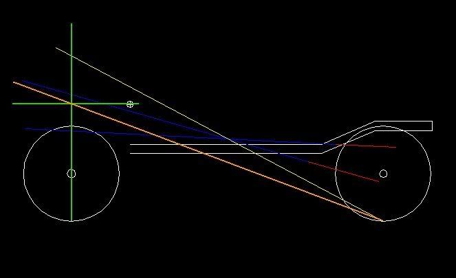
The red lines are the upper and lower trailing arms, if you extend those lines forward (the blue lines), they will intersect. The vertical green line (through the white circle) is the center of the front axle and the horizontal line (through the white circle with the cross) is at the height of the center of gravity. The orange line drawn from the bottom of the rear tire through the intersection of the green lines (we'll call that point A) is the 0% anti-squat line. Anything below that line and the rear suspension will multiply the torque reaction while anything above the line will reduce the torque reaction or provide anti-squat. The light tan line drawn from the bottom of the rear tire through the intersection of the blue lines and continuing on to intersect the vertical green line (we'll call that point B) gives the amount of anti-squat by the following calculation: (B-A)/A*100= C where C is anti-squat in %.
C2 and C3 Corvettes with the single trailing arm have no anti-squat capability and depend solely on the spring to counter the torque reaction on acceleration. If you've ever sat in a C2/3 and put it in gear or goosed the throttle (in an automatic), you've felt the rear end drop when the spring absorbed the torque. The big blocks have stiffer springs because of their higher torque and as a result, the ride suffered.
The C4s incorporated anti-squat geometry which allowed lower spring rates and a more comfortable ride. But because of the trailing arm arrangement, as you lower the car or as it squats on acceleration, it changes the angle of the arms in the direction which causes a reduction in anti-squat. Anti-squat is desired from a road racing perspective so the chassis doesn't get upset (suspension movements are minimized) when loaded or unloaded by the engine. Weight transfer is desired from a drag racing perspective...they are two different things.
The C5/6 Corvettes went to a double wishbone rear suspension. It still has anti-squat but you use the line drawn through the pivot points of the upper and lower control arms to establish the red lines in the drawing above. A couple of advantages to this arrangement are: 1) as you lower the car, anti-squat increases (the center of gravity, point A decreases while point B remains the same distance above A), 2) as the rear squats on acceleration, anti-squat increases (the intersection of the two blue lines is higher). With the stiffer chassis of the C5/6 and the increased anti-squat, spring rates are reduced for a better ride and each wheel is allowed to react to bumps instead of the chassis "reacting" to it. Go to an autocross and you'll see the difference between the C2/3/4/5/6 (I'm talking stock to stock). The C2/3s are wallowing all over the place with the front and rear suspension jacking up/down on acceleration/braking and bumps upsetting the chassis. The C4s don't wallow and you don't get much jacking of the suspension, but bumps will upset the chassis. Now watch the C5/6s, no wallowing, not much jacking, and you'll see the wheels go over the bumps without upsetting the chassis (unless they're big bumps)...very refined.


