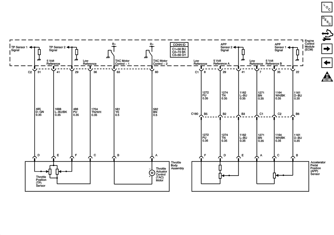
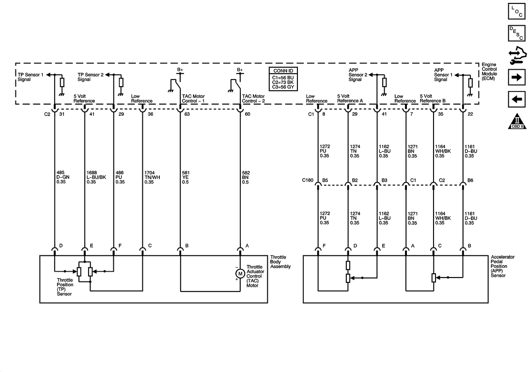
Accelerator pedal position (APP) sensor wiring diagram - Anyone help?
#1
Racer


Thread Starter
Hello everyone,
I'm looking for a wiring diagram from a service manual for this sensor.
It has 3 internal sensors to record pedal position and I need to know which wires are for which sensors for a hookup to my boost controller.
Can anyone help me out?
Thanks,
Scott
I'm looking for a wiring diagram from a service manual for this sensor.
It has 3 internal sensors to record pedal position and I need to know which wires are for which sensors for a hookup to my boost controller.
Can anyone help me out?

Thanks,
Scott
#3
Race Director


http://forums.corvetteforum.com/c6-t...006-vette.html
Scroll down to SoldSyclone's post# 11. You'll see the colors for wires for the different circuits and the voltages if you need to program the controller with a voltage for WOT or some % of throttle.
I used the APP 1 sensor Dark Blue wire at the top of the accelerator pedal. I used it for an input into my data-logger (a Traqmate) for track sessions. I programmed the Traqmate to indicate idle with a voltage of less than 1 volt, and WOT at 4.39 volts. You can see that in the post it says that WOT is greater than 4 volts, but I'm not sure that's correct - so that's why I used 4.39 volts for WOT.
In all the tuning software (HPTuners, LS2Edit, EFILive, etc.), when you are at WOT the indication in the software is a maximum throttle position of 88%. I think that's because max voltage in the TPS or APP circuits is 4.39 volts, and when compared to the 5 volt reference voltage used for the sensors that's 88% (i.e., 4.39 divided by 5 = .88).
I used the APP inside the cockpit because it was much easier to run the wire to my Traqmate Sensor Unit in the hatch, and I didn't feel like running the wire through the firewall. If your controller is going to be in the engine bay maybe it would be more convenient to tap into the wire at the TPS or the PCM.
Bob

Last edited by BEZ06; 12-08-2008 at 06:46 PM.
#7
#8
maybe old news here but my 05 C-6 has different wire colors and indifferent locations. does anyone have the schematic for my configuration? im trying to reconnect to the C-180 Connector. (wires cut and removed from C-180) (wrecked n salvaged car) thanks to all.
A=pu, B=Lt Bu, C=Tn, D=Br, E=Dk Bu, F=WH/Bk
A=pu, B=Lt Bu, C=Tn, D=Br, E=Dk Bu, F=WH/Bk
#9
Moderator, Tech Contributor

Member Since: Sep 2013
Location: Cape Coral, Florida
Posts: 9,521
Received 2,124 Likes
on
1,689 Posts

maybe old news here but my 05 C-6 has different wire colors and indifferent locations. does anyone have the schematic for my configuration? im trying to reconnect to the C-180 Connector. (wires cut and removed from C-180) (wrecked n salvaged car) thanks to all.
A=pu, B=Lt Bu, C=Tn, D=Br, E=Dk Bu, F=WH/Bk
A=pu, B=Lt Bu, C=Tn, D=Br, E=Dk Bu, F=WH/Bk
#10
Thank you for the reply. but as I stated my wiring color and locations are different. Wanting to know whats going on here without going thru a bunch of APP testing.
I really do appreciate the help. and I have saved the diagram for future use as im sure I will need it.
I really do appreciate the help. and I have saved the diagram for future use as im sure I will need it.
#11
Ok so I finally started my car. had to remotely apply power and ground to start relay. disabled VATS via HP Tuners. car does not have ground signal to fuel pup relay so I by passed and ran separate ground to activate. car starts and runs but no accelerator. tried four different combinations of wiring diagrams I have. none work. Note; I do not have a TAC !! my 2005 vette harness does not use one..
any ideas why I do not have signals to power things and no operating APP?
thanks
any ideas why I do not have signals to power things and no operating APP?
thanks


