
[DIY: TR6060 manual transmission teardown and rebuild]
 11-05-2012, 02:29 PM
#1
Le Mans Master

Thread Starter
Member Since: May 2011
Location: Tampa FL (formerly Justinjor)
Posts: 5,022
Likes: 0
Received 14 Likes
on
9 Posts
Tech Contributor
St. Jude Donor '11-'12-'13-'14

Disclaimer: The following procedures should be performed at your own risk. I am not a certified TR6060 mechanic and only relied on common sense and a detail-oriented brain to perform this rebuild.
Background: After 210 dragstrip passes and roughly 20k hard street miles, I finally had a catastrophic failure in my car as the 27 spline output shaft in my TR6060 let go, leaving me dead in the water and needing a tow. Up until this point I had done 100% of the wrenching on my car and frowned at the idea of having to rely on someone else to rebuild the transmission. After much deliberation, I chose to take on the project myself and ordered upgraded parts and a new 30 spline output shaft. I also ordered a set of carbon blocker rings and bronze shift fork pads to go along with my beefier mainshaft. The car only had 35k miles before the break and has 0 issues with the transmission. It shifted smoothly and perfectly so I did not expect to find any broken or otherwise damaged parts.

Tools: In addition to a regular mechanics toolset, you will need the following specialty tools:
This guide assumes you have the knowledge and capability to put the car on jackstands, remove the rear cradle, the diff, and subsequently remove the transmission. SlickShoes has a great how-to thread located here which will guide you if you're unsure.
http://forums.corvetteforum.com/c6-t...ion-4-0-a.html
**TEARDOWN**
**Important**
Take note of the orientation and location of each piece you remove. Many of the parts are installed one way and cannot be reversed so you'll want to make sure you remove and set them aside in the exact order and orientation in which they came out.
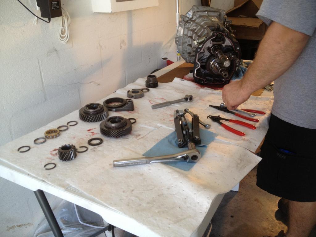
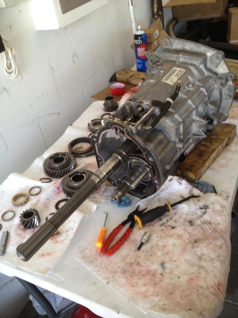
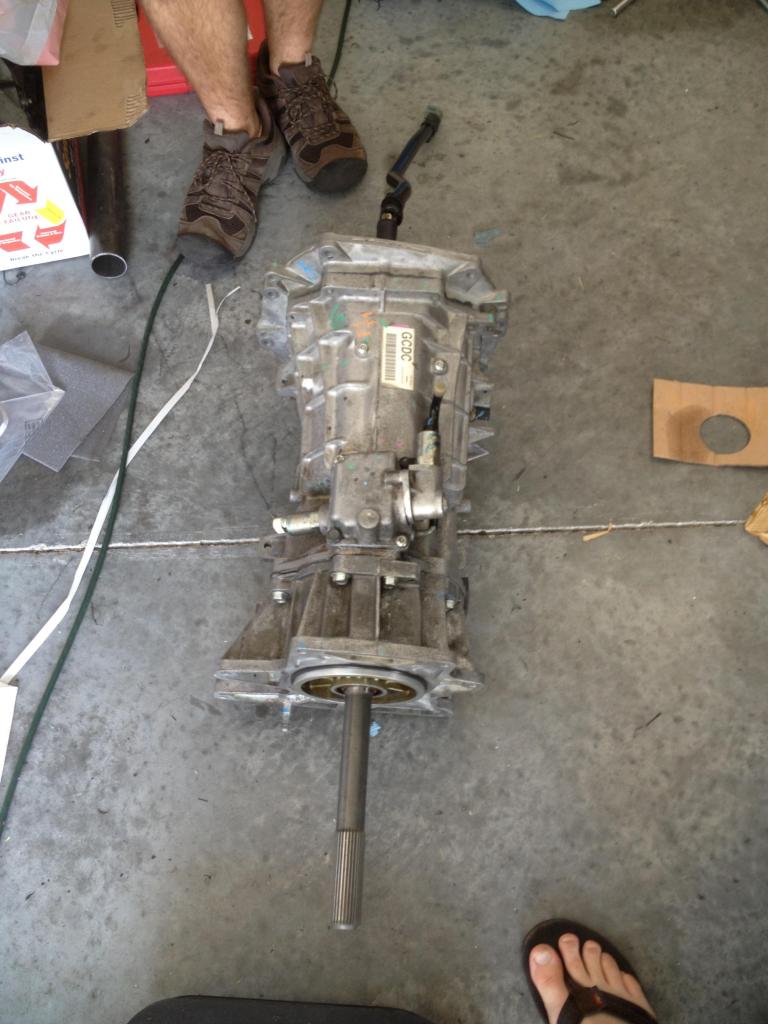
Here is your starting point. The transmission is out of the car and ready to be torn down.
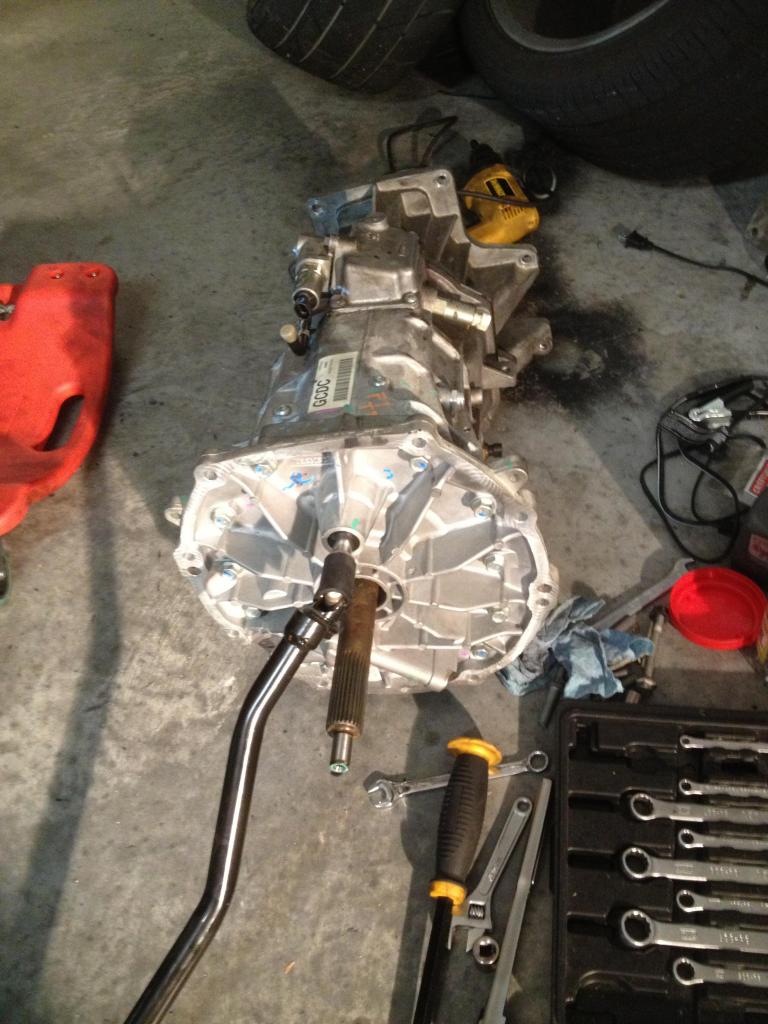
1) Start by removing the shift rod. This is done by rolling the rubber insulation forward and taping the roll pin out with a punch.
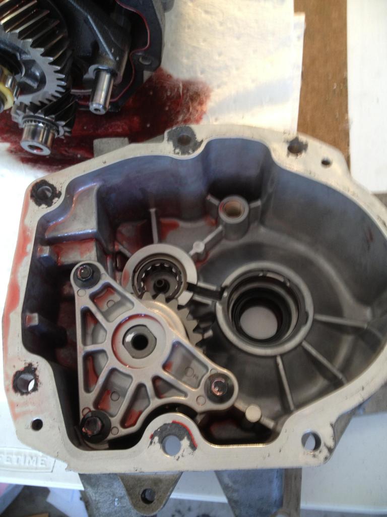
2) Remove the tailshaft housing. It will likely be glued to the main housing with silicone/gasket so a little tap with the rubber mallet should set it free. Once it is broken free, gently slide it off making sure not to scuff or scratch the bearings.
Here is the inside of the tailshaft housing. You can see the output shaft seal, reverse idler, and countershaft bearing.
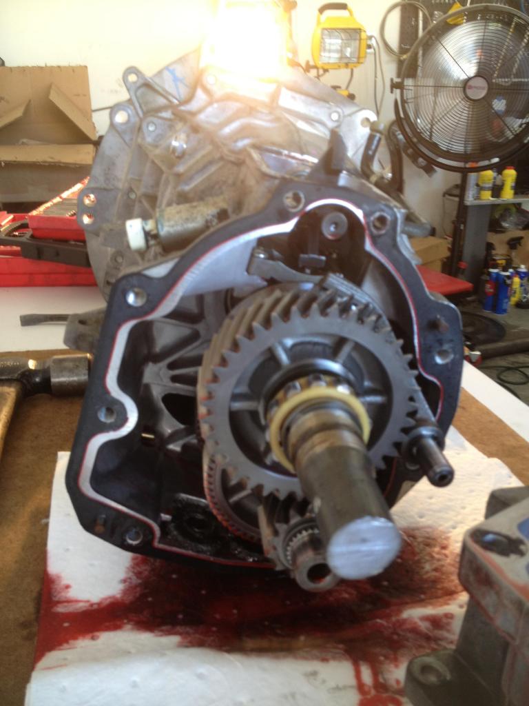
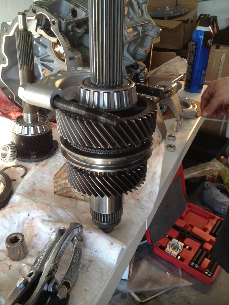
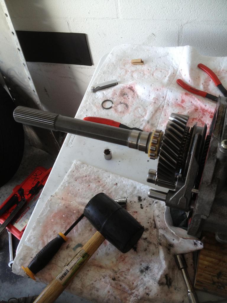
3) With the tailshaft housing removed, you'll have access to 5th, 6th, and reverse gears and also the accompanying shift forks. In this picture, you can see what's left of the output shaft after a quick cut with the band saw.
4) Remove the snapring and begin sliding the gears, spacers, and misc pieces off the shaft one by one. Most of the parts slide off but you will need to use the gear puller to remove the pressed on 5th, 6th, and reverse gears. The shift fork is held in place with a retainer/stop that is attached to the shift rail with a roll pin.
In this picture, you can see the output shaft bearing, gears, blocker assembly, 5/6 shift fork, and 5th gear.
Below that, you see reverse gear and another blocker/gear combination. Reverse gear is pressed on and will need to be removed with the puller.
5) Continue removing the Reverse shift fork and gears on the countershaft and set them aside in the correct order. Once you've removed all the pieces from the rear, you should be left with 2 bare shafts and nothing attached to them.
6) Remove the reverse lock-out solenoid from the top of the transmission. Be careful not to lose the spring and roller guide assembly as it will fall out once you take it off. It is held on with 2 torx and 2 13mm bolts.
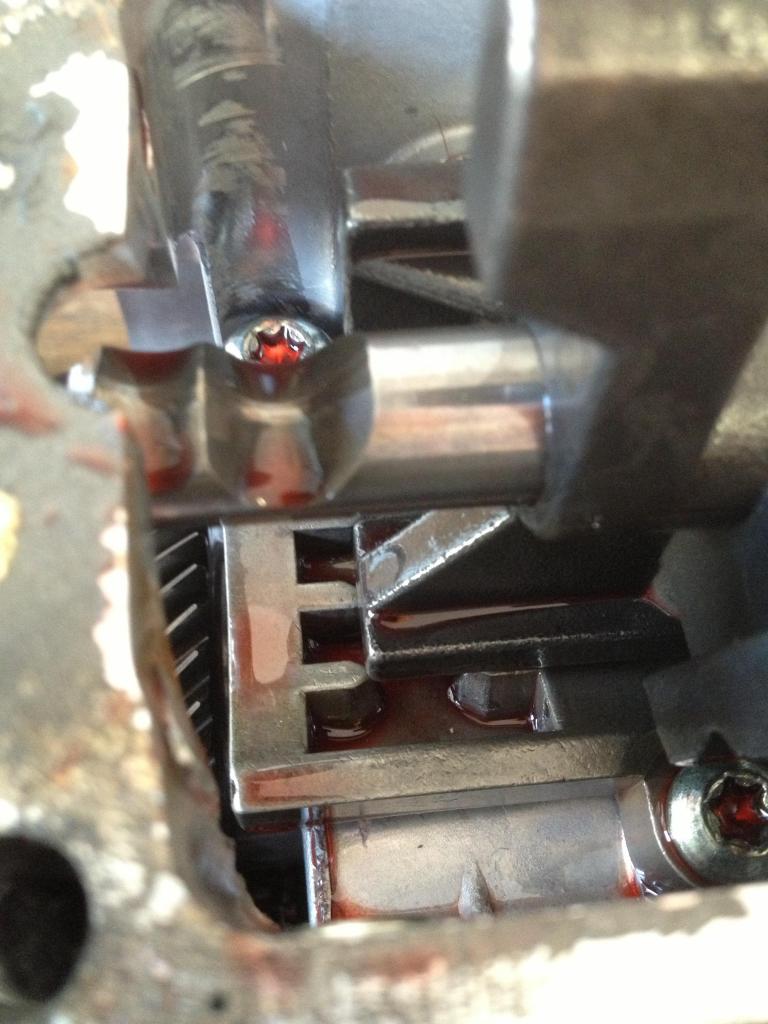
With the solenoid and cover removed, you can see the shift pattern and gear selector attached to the main shift rail.
Remove the detent from the outside of the case.
Use a punch to tap the roll pin down and out of the shift rail being careful not to lose it.
In this picture, you can see the location where the roller guide is positioned on the shift rail.
7) There are 2 torx bolts near the front of the transmission case that need to be removed. They are guide pins for the shift fork rails.
8) Now that you're done with the rear, you can shift your focus to the front half of the transmission.
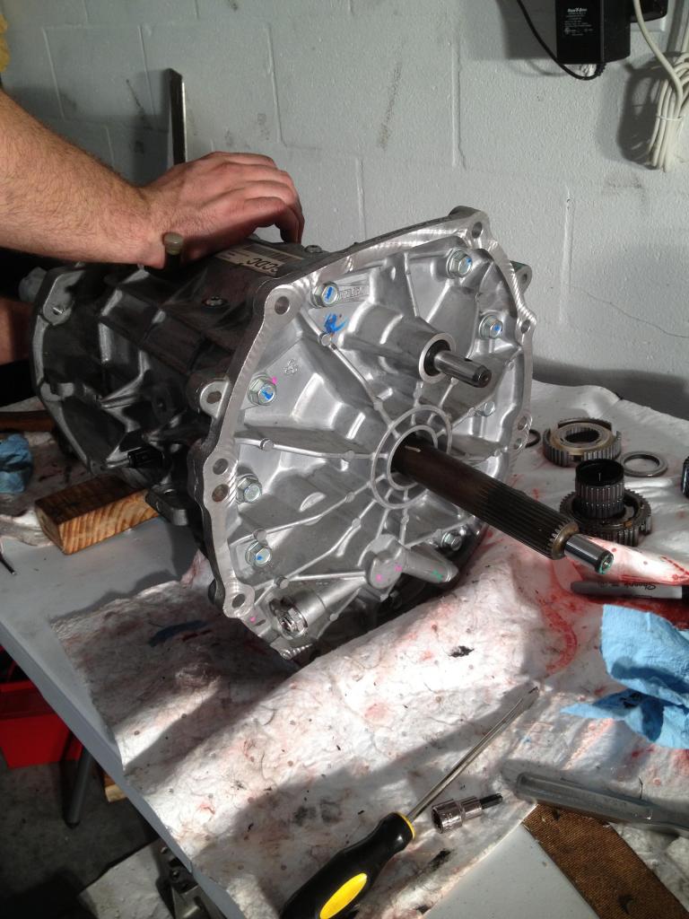
Begin by removing the 15mm front cover bolts.
With the cover bolts removed, gently tap on the cover to break the bond free. If you have a Z51 or other model with a transmission cooler, be very careful not to break the filter as you slide the cover off.
The input shaft bearing rides inside the cover so you will need to reach in and support it while removing the cover. The other option is to place the transmission vertical and remove the cover with gravity on your side.
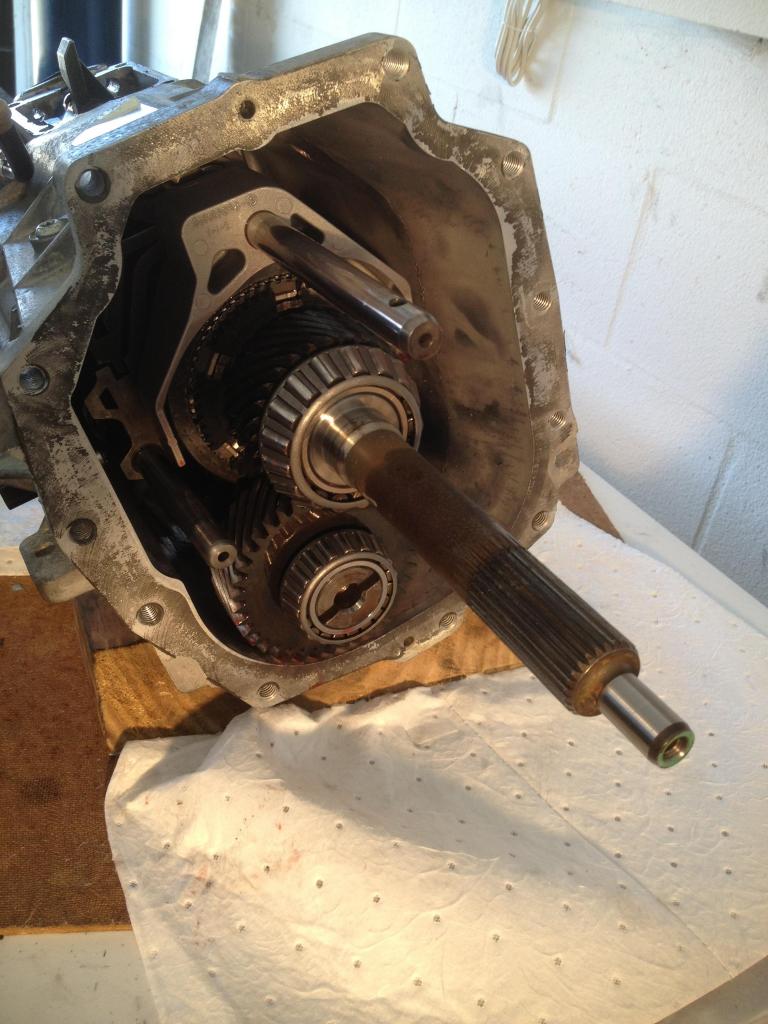
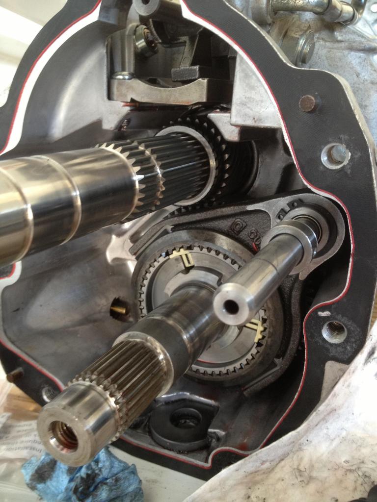
With the cover removed, you can see the input shaft, shift fork, and counter shaft.
9) Remove the 5/6 and reverse shift fork rails. They are the lower of the 2 sets of rails in the above picture.
With the cover gone, the shafts have some wiggle room so you can move them around and slide the shift rail out. The 2 main shafts and 1/2 3/4 shift rails will be removed as one big unit in the next step.
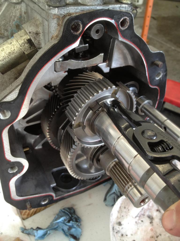
10) CAREFULLY slide the output shaft, counter shaft, and shift fork rails out of the case as one big piece. Be careful not to ding up the inside of the case where the bearings seat.
Remember that the gear selector on the top of the case is free and will fall once the shift rail has been removed. Don't lose the roll pin!
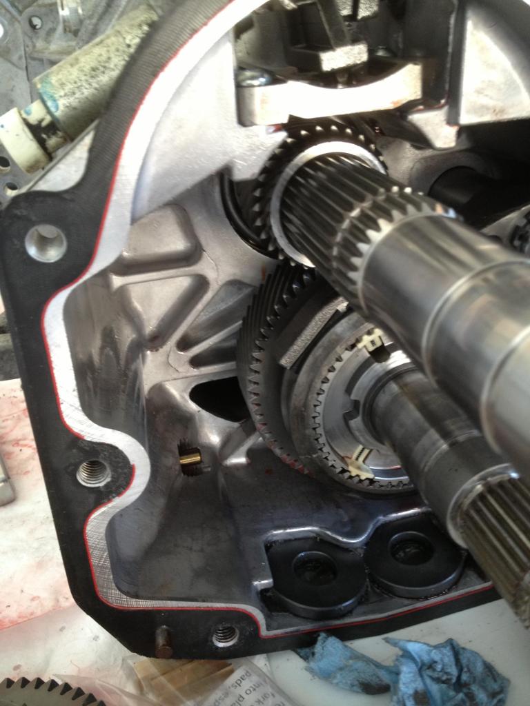
Here is what you should see before removal. If you look closely, you can see the black plastic shift fork pads.
And here it is on the table, ready for the rest of the teardown. The counter shaft is one solid piece and can be set aside for now.
This is what you should be left with, a bare case. Here you can see the 2 shift rail holes an also the locations where the bearings reside.
Gear selector/shift rail removed
11) Set aside the input shaft and 3rd gear synchro/blocker assembly. You won't need these for awhile.
12) Starting at the front of the output shaft, remove the bearing with the bearing cutter tool and gear puller. Be very careful not to damage the cage for the rollers. Once the splitter has a good grip on the outer edge of the bearing, you can use the gear puller to gentle pull the bearing off the shaft.
With the bearing removed, you can slide off the gears and synchro assemblies and set them aside. Again--be very mindful of the exact order and orientation of their removal.
13) With the front-half of the output shaft removed, you're onto the final step in the disassembly. Remove the rear bearing with the bearing cutter/gear puller combo and then remove the rest of the gears, synchros and blocker assemblies.
**Rebuild**
In my opinion, the rebuild process was easier and required less use of the special tools so if you've made it this far, you're almost done.
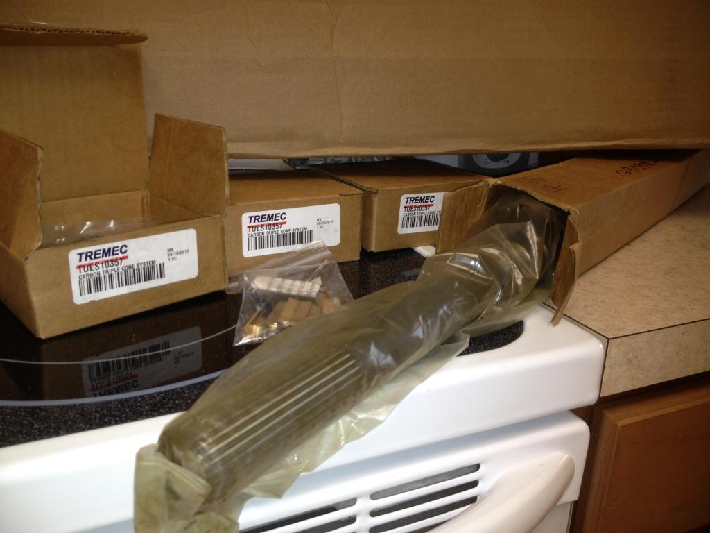
I'm a big proponent of "while you're in there" and chose to upgrade the blockers and bronze shift fork pads in addition to the much stronger 30 spline output shaft.
Also, aside from the bearings, the gears that previously required the gear puller for removal can be baked in an oven at 400* for 20-30 minutes to expand the metal instead of using the press. Once they have baked, you can remove them and slide them in place with no resistance but you'll need to act quickly. You only have about a 30 second window from the time you pull the pieces out, until you put them in place before they cool off and subsequently return to their original size.
When reinstalling the new synchros and gears, make sure to use a small amount of transmission fluid to lubricate everything. I made sure I coated each side of all blocker assemblies, and each gear prior to installation.
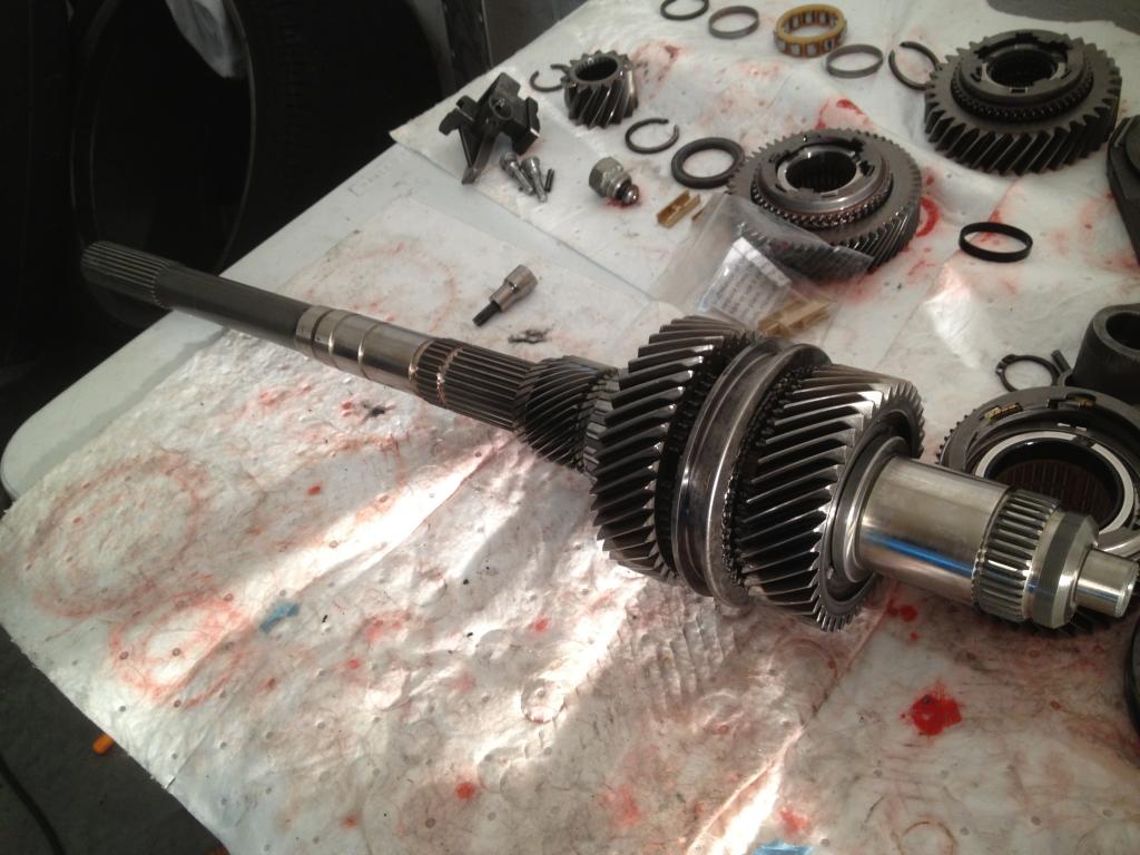
14) You should now have a bare output shaft and a LOT of small pieces all organized on your table ready for installation. It should look something like this.
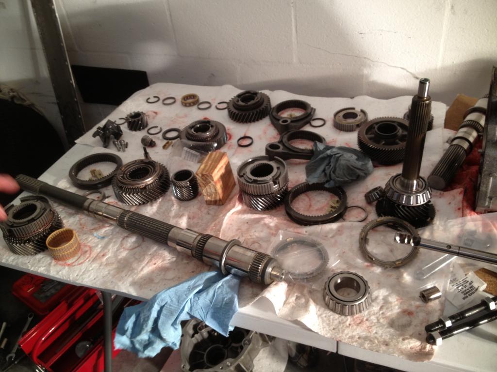
15) Everything goes in the reverse of how it came out so we'll start with the pieces we just removed.
Here is a picture of the stock blocker rings compared to the stronger carbon counterparts.
16) I replaced the 1/2 and 3/4 shift fork pads with stronger bronze pieces as they showed some obvious wear. The 5/6 and reverse, as noted before, were left as-is.
17) Reinstall the rear bearing.
18) Reinstall the front gears, synchros, and blocker assemblies and press on the front bearing.
If you purchased upgraded parts, now is the time to install them.
19) Now that you have the front half of the output shaft assembled, it's time for the most challenging part of the whole process. The output shaft, counter shaft, and shift forks all have to find their way back in the case at the same time. There is not a lot of room and it can definitely be a pain but you'll want to take your time as the bearings need to find their home without scratching up or otherwise damaging anything.
I found it easier to build a platform out of a wheel and 2 race ramps so the long output shaft had somewhere to go. It will take a lot of tinkering and getting everything just right as the shift forks like to move around and not line up where they're supposed to be.
In this picture, you can see the detent that you would have removed in step 6.
20) Now that you have the main pieces in place, you can reinstall the 5/6 and reverse shift fork. Once they're in place, reinstall the guide pins that you removed in step 7. If you look closely, you can see the bronze shift fork pads.
21) As you're sliding in the assembly, you'll also need to position the gear shift lever in place so the shift rail can slide through it before the 2 shafts bottom out in their bearing carriers.
22) I replaced the stock blocker for 3rd gear with the carbon version just before installing it. Once you have everything in place, you can get the front cover ready for reinstallation.
23) Clean off the old silicone on both the transmission case and the front cover. Use fresh silicone to seal the case. I used the black permatex silicone for its oil-resistant properties. Once it dries, it won't leak.
24) When you reinstall the front cover, be careful to line up the input shaft, shift rail, and the fluid pump(if equipped). Also be careful not to break the plastic filter for the fluid pump.
25) Once the front cover is on, you can focus your attention on the rear half of the output shaft. Reinstall the reverse lockout solenoid and cover. Again, make sure to clean both mating surfaces and apply fresh silicone to seal it.
26) Reinstall the synchro/blocker assembly on the counter shaft. Also reinstall the shift fork and retaining ring.
27) After heating 5th gear in the oven for 30 minutes, reinstall it on the output shaft, making sure it sits snugly with the previously installed bearing.
Here you can see 5th gear on the output shaft, and also the blocker/synchro/shift fork assembly installed on the counter shaft.
28) Now is a good time to clean off the 2 magnets inside the case. Mine had a good amount of "fuzz" but nothing too alarming. My research told me that, like oil changes, it's normal to find some metal flakes and debris attached to the magnets. After all, that's what they're there for--to catch small metal pieces.
You can see the 2 round magnets attached to the bottom of the case.
29) Reinstall the gears, clips, synchro assemblies, etc, in the same order they were removed. Don't forget the oven trick.
30) Reinstall the reverse shift fork, reverse gear, and you're almost done.
31) Clean both mating surfaces and reinstall the tailshaft housing.
32) Reinstall the shift rod and you're all done.
Once you have everything buttoned up, go ahead and cycle through each gear with the shift rod and check that both the input and output shaft rotate together. Make sure there is no binding or other strange sensation in the operation. The shafts should rotate freely with slightly higher effort required due to the lack of fluid in the case.
The output shaft should spin at a different speed for each gear and reverse should spin the opposite way.
Hope you enjoyed the write-up!
Background: After 210 dragstrip passes and roughly 20k hard street miles, I finally had a catastrophic failure in my car as the 27 spline output shaft in my TR6060 let go, leaving me dead in the water and needing a tow. Up until this point I had done 100% of the wrenching on my car and frowned at the idea of having to rely on someone else to rebuild the transmission. After much deliberation, I chose to take on the project myself and ordered upgraded parts and a new 30 spline output shaft. I also ordered a set of carbon blocker rings and bronze shift fork pads to go along with my beefier mainshaft. The car only had 35k miles before the break and has 0 issues with the transmission. It shifted smoothly and perfectly so I did not expect to find any broken or otherwise damaged parts.
Tools: In addition to a regular mechanics toolset, you will need the following specialty tools:
- Hydraulic press-I bought one from a local tool supply company
- Snap-ring plier set-there are a few different snap ring sizes and styles that hold everything together so having a full set is a must
- Bearing splitter(puller)-Also purchased at a local tool supply company
- Punch set-the shift arm, shift fork, and some other misc pieces are held on with roll pins so you'll need a good punch set to hammer them out
- T-40 torx
- Gear puller with extended arms, depending on what is left of your output shaft
- Portable band saw-came in very handy to trim down the broken output shaft and make a flat surface for the puller to pull against
- Transmission jack
- 5'(or larger) table to lay everything out and keep it organized
- Rubber mallet
- Feeler gauges
This guide assumes you have the knowledge and capability to put the car on jackstands, remove the rear cradle, the diff, and subsequently remove the transmission. SlickShoes has a great how-to thread located here which will guide you if you're unsure.
http://forums.corvetteforum.com/c6-t...ion-4-0-a.html
**TEARDOWN**
**Important**
Take note of the orientation and location of each piece you remove. Many of the parts are installed one way and cannot be reversed so you'll want to make sure you remove and set them aside in the exact order and orientation in which they came out.
Here is your starting point. The transmission is out of the car and ready to be torn down.
1) Start by removing the shift rod. This is done by rolling the rubber insulation forward and taping the roll pin out with a punch.
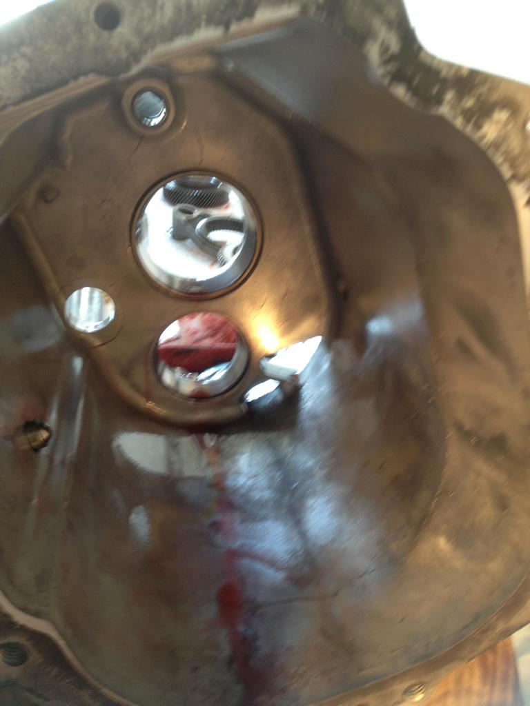
2) Remove the tailshaft housing. It will likely be glued to the main housing with silicone/gasket so a little tap with the rubber mallet should set it free. Once it is broken free, gently slide it off making sure not to scuff or scratch the bearings.
Here is the inside of the tailshaft housing. You can see the output shaft seal, reverse idler, and countershaft bearing.
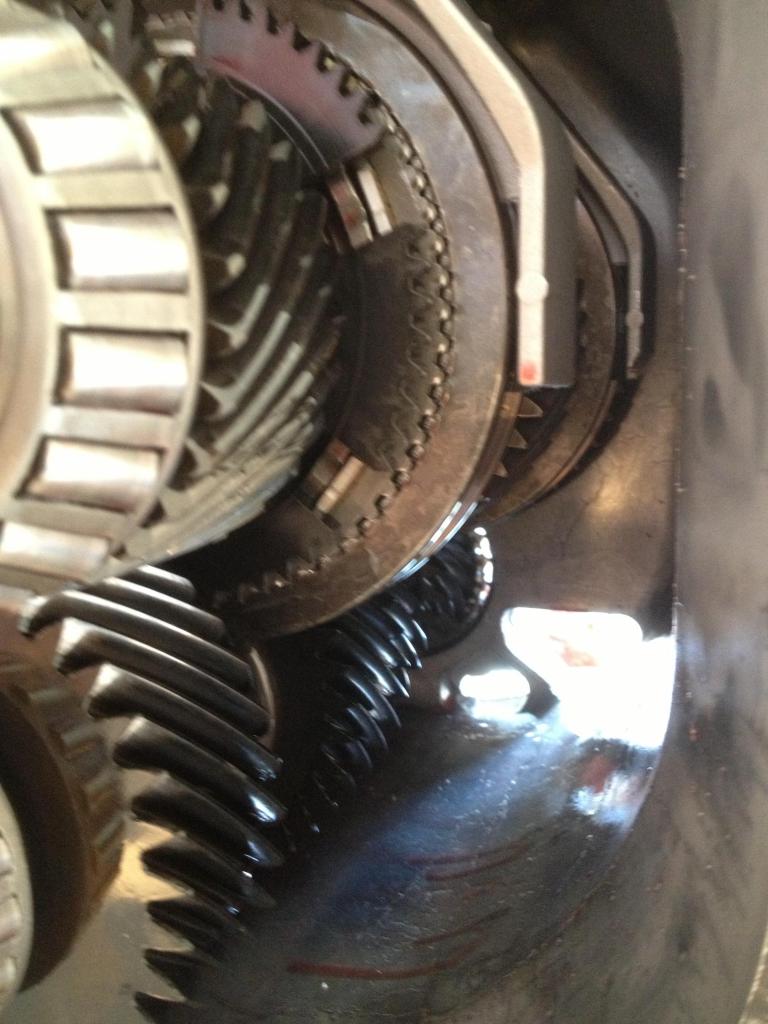
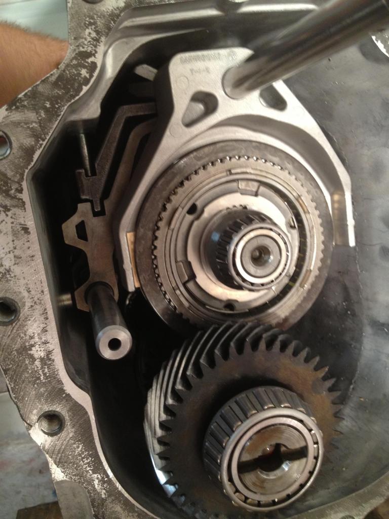
3) With the tailshaft housing removed, you'll have access to 5th, 6th, and reverse gears and also the accompanying shift forks. In this picture, you can see what's left of the output shaft after a quick cut with the band saw.
4) Remove the snapring and begin sliding the gears, spacers, and misc pieces off the shaft one by one. Most of the parts slide off but you will need to use the gear puller to remove the pressed on 5th, 6th, and reverse gears. The shift fork is held in place with a retainer/stop that is attached to the shift rail with a roll pin.
In this picture, you can see the output shaft bearing, gears, blocker assembly, 5/6 shift fork, and 5th gear.
Below that, you see reverse gear and another blocker/gear combination. Reverse gear is pressed on and will need to be removed with the puller.
5) Continue removing the Reverse shift fork and gears on the countershaft and set them aside in the correct order. Once you've removed all the pieces from the rear, you should be left with 2 bare shafts and nothing attached to them.
6) Remove the reverse lock-out solenoid from the top of the transmission. Be careful not to lose the spring and roller guide assembly as it will fall out once you take it off. It is held on with 2 torx and 2 13mm bolts.
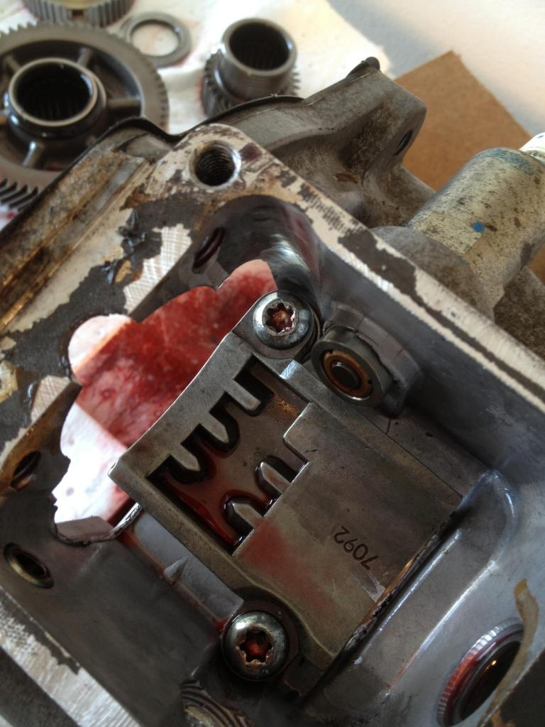
With the solenoid and cover removed, you can see the shift pattern and gear selector attached to the main shift rail.
Remove the detent from the outside of the case.
Use a punch to tap the roll pin down and out of the shift rail being careful not to lose it.
In this picture, you can see the location where the roller guide is positioned on the shift rail.
7) There are 2 torx bolts near the front of the transmission case that need to be removed. They are guide pins for the shift fork rails.
8) Now that you're done with the rear, you can shift your focus to the front half of the transmission.
Begin by removing the 15mm front cover bolts.
With the cover bolts removed, gently tap on the cover to break the bond free. If you have a Z51 or other model with a transmission cooler, be very careful not to break the filter as you slide the cover off.
The input shaft bearing rides inside the cover so you will need to reach in and support it while removing the cover. The other option is to place the transmission vertical and remove the cover with gravity on your side.
With the cover removed, you can see the input shaft, shift fork, and counter shaft.
9) Remove the 5/6 and reverse shift fork rails. They are the lower of the 2 sets of rails in the above picture.
With the cover gone, the shafts have some wiggle room so you can move them around and slide the shift rail out. The 2 main shafts and 1/2 3/4 shift rails will be removed as one big unit in the next step.
10) CAREFULLY slide the output shaft, counter shaft, and shift fork rails out of the case as one big piece. Be careful not to ding up the inside of the case where the bearings seat.
Remember that the gear selector on the top of the case is free and will fall once the shift rail has been removed. Don't lose the roll pin!
Here is what you should see before removal. If you look closely, you can see the black plastic shift fork pads.
And here it is on the table, ready for the rest of the teardown. The counter shaft is one solid piece and can be set aside for now.
This is what you should be left with, a bare case. Here you can see the 2 shift rail holes an also the locations where the bearings reside.
Gear selector/shift rail removed
11) Set aside the input shaft and 3rd gear synchro/blocker assembly. You won't need these for awhile.
12) Starting at the front of the output shaft, remove the bearing with the bearing cutter tool and gear puller. Be very careful not to damage the cage for the rollers. Once the splitter has a good grip on the outer edge of the bearing, you can use the gear puller to gentle pull the bearing off the shaft.
With the bearing removed, you can slide off the gears and synchro assemblies and set them aside. Again--be very mindful of the exact order and orientation of their removal.
13) With the front-half of the output shaft removed, you're onto the final step in the disassembly. Remove the rear bearing with the bearing cutter/gear puller combo and then remove the rest of the gears, synchros and blocker assemblies.
**Rebuild**
In my opinion, the rebuild process was easier and required less use of the special tools so if you've made it this far, you're almost done.
I'm a big proponent of "while you're in there" and chose to upgrade the blockers and bronze shift fork pads in addition to the much stronger 30 spline output shaft.
Also, aside from the bearings, the gears that previously required the gear puller for removal can be baked in an oven at 400* for 20-30 minutes to expand the metal instead of using the press. Once they have baked, you can remove them and slide them in place with no resistance but you'll need to act quickly. You only have about a 30 second window from the time you pull the pieces out, until you put them in place before they cool off and subsequently return to their original size.
When reinstalling the new synchros and gears, make sure to use a small amount of transmission fluid to lubricate everything. I made sure I coated each side of all blocker assemblies, and each gear prior to installation.
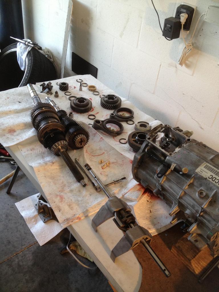
14) You should now have a bare output shaft and a LOT of small pieces all organized on your table ready for installation. It should look something like this.
15) Everything goes in the reverse of how it came out so we'll start with the pieces we just removed.
Here is a picture of the stock blocker rings compared to the stronger carbon counterparts.
16) I replaced the 1/2 and 3/4 shift fork pads with stronger bronze pieces as they showed some obvious wear. The 5/6 and reverse, as noted before, were left as-is.
17) Reinstall the rear bearing.
18) Reinstall the front gears, synchros, and blocker assemblies and press on the front bearing.
If you purchased upgraded parts, now is the time to install them.
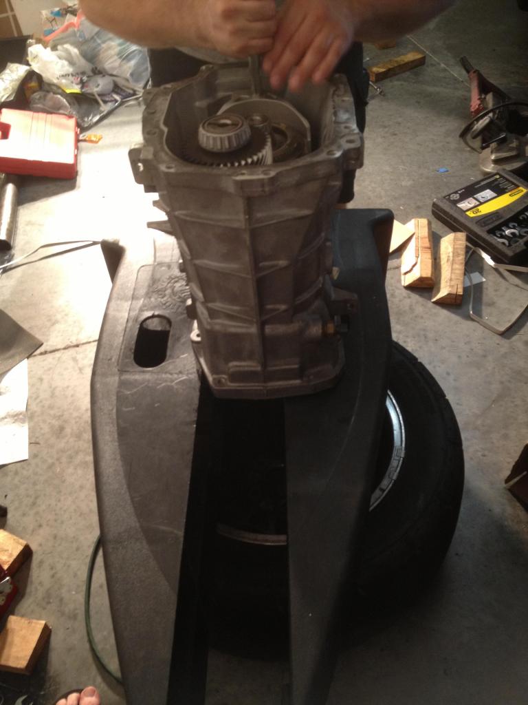
19) Now that you have the front half of the output shaft assembled, it's time for the most challenging part of the whole process. The output shaft, counter shaft, and shift forks all have to find their way back in the case at the same time. There is not a lot of room and it can definitely be a pain but you'll want to take your time as the bearings need to find their home without scratching up or otherwise damaging anything.
I found it easier to build a platform out of a wheel and 2 race ramps so the long output shaft had somewhere to go. It will take a lot of tinkering and getting everything just right as the shift forks like to move around and not line up where they're supposed to be.
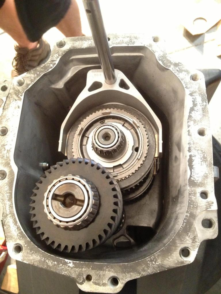
In this picture, you can see the detent that you would have removed in step 6.
20) Now that you have the main pieces in place, you can reinstall the 5/6 and reverse shift fork. Once they're in place, reinstall the guide pins that you removed in step 7. If you look closely, you can see the bronze shift fork pads.
21) As you're sliding in the assembly, you'll also need to position the gear shift lever in place so the shift rail can slide through it before the 2 shafts bottom out in their bearing carriers.
22) I replaced the stock blocker for 3rd gear with the carbon version just before installing it. Once you have everything in place, you can get the front cover ready for reinstallation.
23) Clean off the old silicone on both the transmission case and the front cover. Use fresh silicone to seal the case. I used the black permatex silicone for its oil-resistant properties. Once it dries, it won't leak.
24) When you reinstall the front cover, be careful to line up the input shaft, shift rail, and the fluid pump(if equipped). Also be careful not to break the plastic filter for the fluid pump.
25) Once the front cover is on, you can focus your attention on the rear half of the output shaft. Reinstall the reverse lockout solenoid and cover. Again, make sure to clean both mating surfaces and apply fresh silicone to seal it.
26) Reinstall the synchro/blocker assembly on the counter shaft. Also reinstall the shift fork and retaining ring.
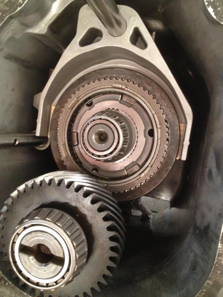
27) After heating 5th gear in the oven for 30 minutes, reinstall it on the output shaft, making sure it sits snugly with the previously installed bearing.
Here you can see 5th gear on the output shaft, and also the blocker/synchro/shift fork assembly installed on the counter shaft.
28) Now is a good time to clean off the 2 magnets inside the case. Mine had a good amount of "fuzz" but nothing too alarming. My research told me that, like oil changes, it's normal to find some metal flakes and debris attached to the magnets. After all, that's what they're there for--to catch small metal pieces.
You can see the 2 round magnets attached to the bottom of the case.
29) Reinstall the gears, clips, synchro assemblies, etc, in the same order they were removed. Don't forget the oven trick.
30) Reinstall the reverse shift fork, reverse gear, and you're almost done.
31) Clean both mating surfaces and reinstall the tailshaft housing.
32) Reinstall the shift rod and you're all done.
Once you have everything buttoned up, go ahead and cycle through each gear with the shift rod and check that both the input and output shaft rotate together. Make sure there is no binding or other strange sensation in the operation. The shafts should rotate freely with slightly higher effort required due to the lack of fluid in the case.
The output shaft should spin at a different speed for each gear and reverse should spin the opposite way.
Hope you enjoyed the write-up!
Last edited by JUIC3D; 11-19-2012 at 09:13 AM. Reason: Updated with more info

The following 4 users liked this post by JUIC3D:
11-05-2012, 03:16 PM
#2
Track Junky

Excellent writeup Justin! I don't think I would have the courage to open up my tranny like that, especially with a dog and 3 kids running thru the garage so often...

 11-05-2012, 03:33 PM
#4
Le Mans Master
Thread Starter
Member Since: May 2011
Location: Tampa FL (formerly Justinjor)
Posts: 5,022
Likes: 0
Received 14 Likes
on
9 Posts
Tech Contributor
St. Jude Donor '11-'12-'13-'14
Thanks Sean. It was a bit nerve-wracking at first but now that I've done it once, I could easily do it again in half the time(like anything else).
I haven't driven it yet. I still need to do a few more things before putting it back on the ground. Suspension, exhaust, etc. I expect to have it back on the road for driving impressions this weekend.
I haven't driven it yet. I still need to do a few more things before putting it back on the ground. Suspension, exhaust, etc. I expect to have it back on the road for driving impressions this weekend.
 11-05-2012, 05:16 PM
#6
Tech Contributor

Justin this is a great write up...I know how long it takes to take the pictures and do the write up - thanks for doing so. Guys like you make the forum great.
I think this thread is worthy of Tech Contributor status if ever there was one!
How's the car drive with the new tranny?
What happened to your diff? Was it damaged too?
I think this thread is worthy of Tech Contributor status if ever there was one!
How's the car drive with the new tranny?
What happened to your diff? Was it damaged too?
11-05-2012, 05:33 PM
#7
Le Mans Master
Thread Starter
Member Since: May 2011
Location: Tampa FL (formerly Justinjor)
Posts: 5,022
Likes: 0
Received 14 Likes
on
9 Posts
Tech Contributor
St. Jude Donor '11-'12-'13-'14
You know--it's funny.. I didn't realize how long it was taking me to type everything out until my stomach started to growl and I realized I had been typing for about 4 hours and it was lunch time. I took a break, ate lunch, and took another couple hours to finish up the last of the paragraphs.
There was no damage to the diff. Since I went with a 30 spline mainshaft, I had to get the pinion machined to accept the larger diameter. Rick@RKT56 is taking care of that for me and I expect to have it back on Saturday.
There was no damage to the diff. Since I went with a 30 spline mainshaft, I had to get the pinion machined to accept the larger diameter. Rick@RKT56 is taking care of that for me and I expect to have it back on Saturday.
The following users liked this post:
72greg (03-08-2020)
11-05-2012, 05:37 PM
#8
Le Mans Master
Thread Starter
Member Since: May 2011
Location: Tampa FL (formerly Justinjor)
Posts: 5,022
Likes: 0
Received 14 Likes
on
9 Posts
Tech Contributor
St. Jude Donor '11-'12-'13-'14
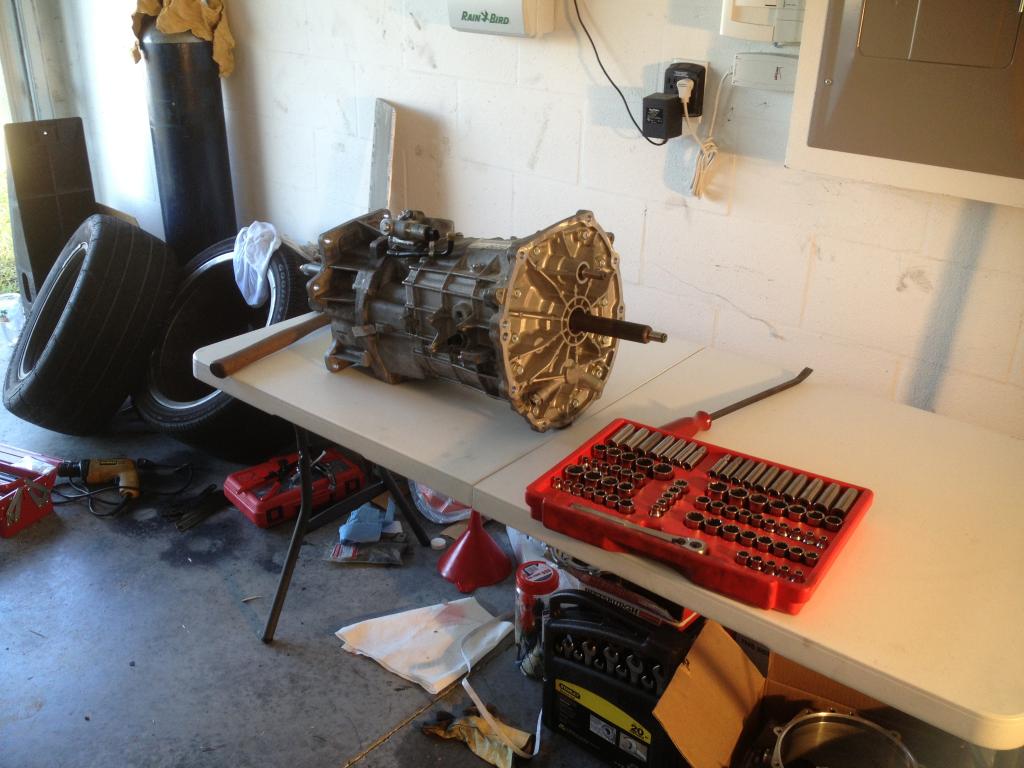
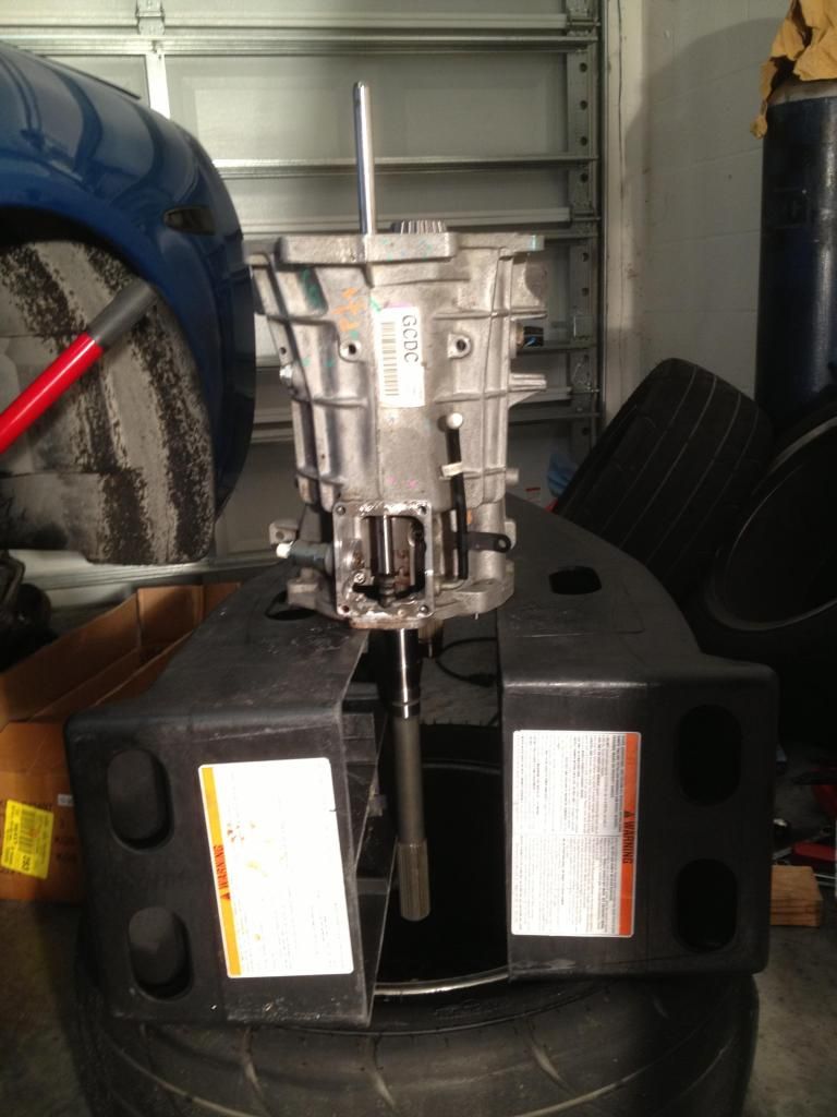
Here's how the car sits right now. Once the pinion comes back I can throw it in, fill her with fluid, and by then I'll have the rest of the suspension and exhaust all bolted up.

The following users liked this post:
72greg (03-08-2020)


 11-05-2012, 08:38 PM
#13
Le Mans Master
Thread Starter
Member Since: May 2011
Location: Tampa FL (formerly Justinjor)
Posts: 5,022
Likes: 0
Received 14 Likes
on
9 Posts
Tech Contributor
St. Jude Donor '11-'12-'13-'14
Thanks everyone. I did not see any other write ups like this so hopefully it can help someone in the future.
The following users liked this post:
72greg (03-08-2020)


 11-06-2012, 06:28 AM
#17
Tech Contributor
When I watched a guy rebuild a trans, seems like I recall he used a 5 gallon plastic Home Depot bucket to set the trans in when resetting the gears. Is that deep enough? I might be mistaken.
Also, that step of holding the cluster and shift rails together looks tough...I'm wondering if the vinyl strapping material you use to strap orchids to palm trees might be a nice choice? It's super stretchy, very thin, about 1/2" wide but holds tight and doesn't tear easily so it seems it would be easy to remove once the cluster is in. I'm envisioning a double wrap of the strap, leaving the ends hanging out, and then just unwrap it when the cluster is installed. Think that would help or is it pretty easy to hold together?
Also, that step of holding the cluster and shift rails together looks tough...I'm wondering if the vinyl strapping material you use to strap orchids to palm trees might be a nice choice? It's super stretchy, very thin, about 1/2" wide but holds tight and doesn't tear easily so it seems it would be easy to remove once the cluster is in. I'm envisioning a double wrap of the strap, leaving the ends hanging out, and then just unwrap it when the cluster is installed. Think that would help or is it pretty easy to hold together?
11-06-2012, 06:41 AM
#18
Le Mans Master
Thread Starter
Member Since: May 2011
Location: Tampa FL (formerly Justinjor)
Posts: 5,022
Likes: 0
Received 14 Likes
on
9 Posts
Tech Contributor
St. Jude Donor '11-'12-'13-'14
If you took 2 2x4s and placed them horizontal on the 5 gallon bucket, you could then set the transmission case on the wood and have a nice stable platform from which to work. I imagine that would be plenty tall enough to allow the output shaft room to travel.
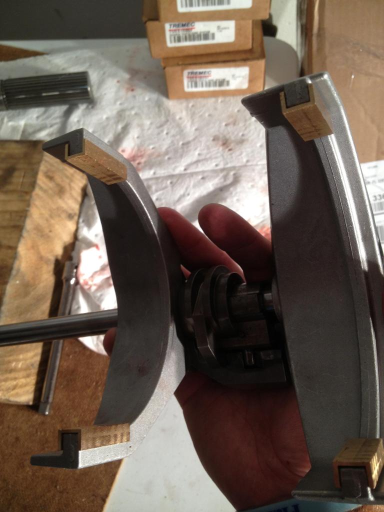
Aside from figuring out how to remove the bearings without damaging them, the step of reinstalling the gear cluster and 1/2 3/4 shift rails was definitely the most challenging.
For starters, it's very heavy, probably around 40lbs and it's very long and awkward.
It took my buddy and I a couple attempts before we finally got everything lined up. It really helps to have the guide pins ready to thread in once you have everything mostly in place. They help keep the shift rails from moving around and out of position.
To be honest, I feel like the straps would be a hindrance as there is really not a lot of room and with so many jagged edges and pieces, you would probably end up snagging them on something and have a headache trying to slide them out.
When you're ready for that step you need to take a breath, focus, be ready for the aggravation that will certainly ensue, and stay positive. It only goes in 1 way so you really can't screw it up.
11-06-2012, 09:12 AM
#19
Le Mans Master
Thread Starter
Member Since: May 2011
Location: Tampa FL (formerly Justinjor)
Posts: 5,022
Likes: 0
Received 14 Likes
on
9 Posts
Tech Contributor
St. Jude Donor '11-'12-'13-'14
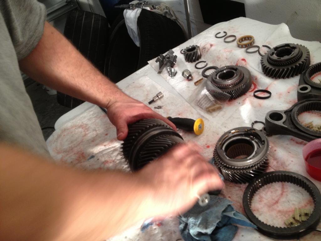
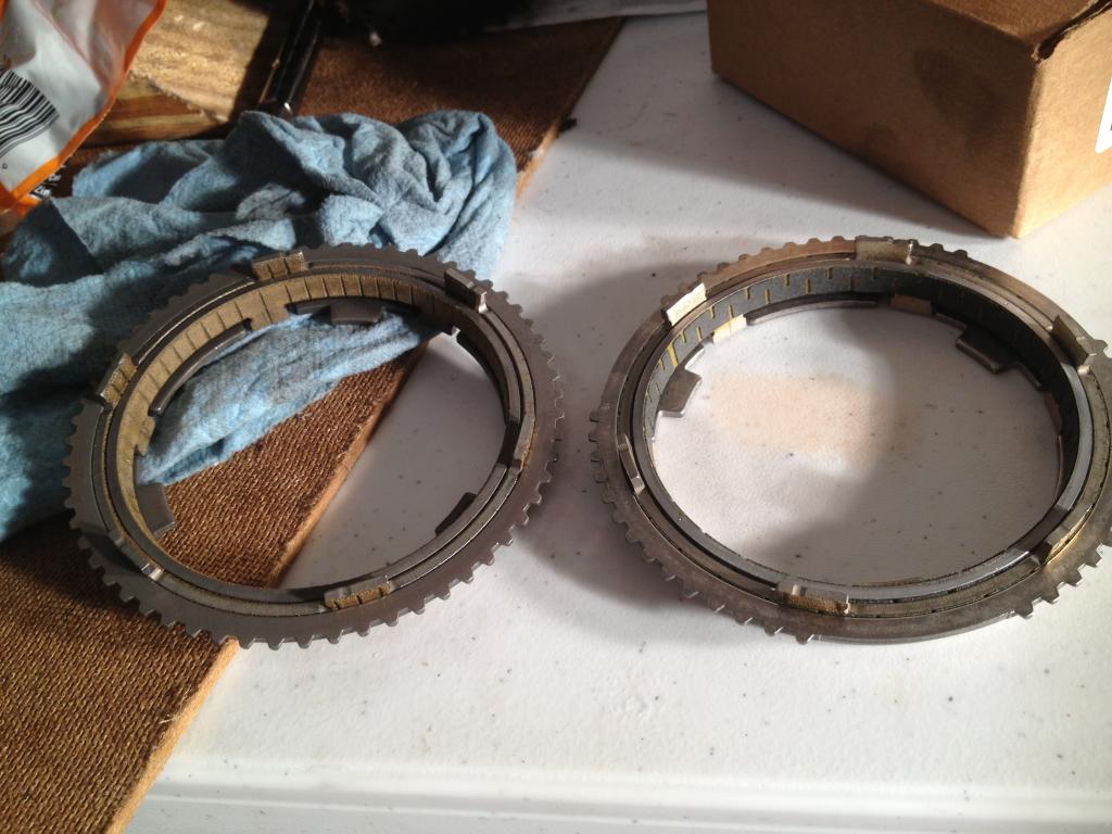
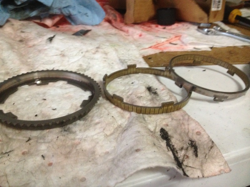
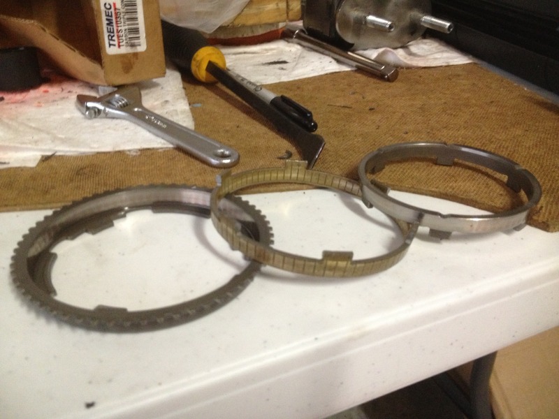
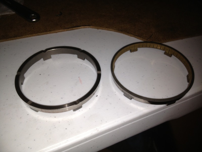
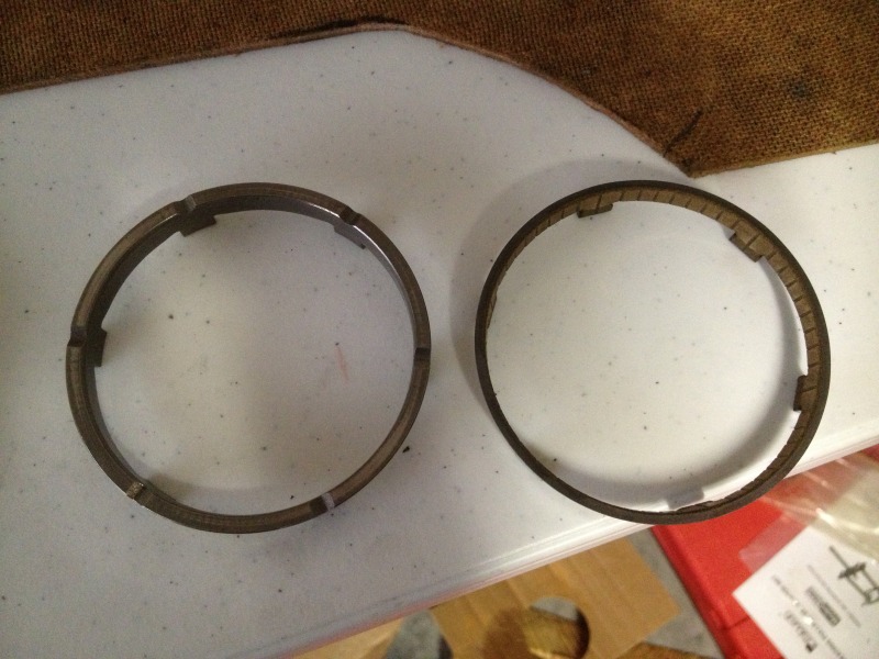
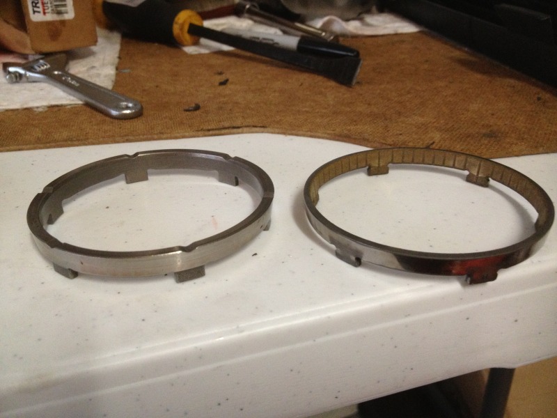
Here are some more pictures of the blocker assemblies that I replaced with the upgraded carbon versions.
I find it a little strange that these 2 blockers have different inner rings.
Each blocker assembly contains 3 pieces: the outer ring(with the teeth) and 2 inner rings that slide inside each other. The 2 outer rings are identical but the inner ring is different between the two. The inner ring of 1 blocker ring has friction on the outside and is smooth in the middle but the inner ring of the 2nd blocker is smooth on both sides and is substantially more thick. I don't recall which gears these belonged too but I did notice they were different when they were replaced.

