
Wire size
 03-27-2015, 05:14 PM
#1
Racer


Thread Starter

Replaced my alternator with a new 170 amp unit, I need to replace the battery cables with a larger size (ampere rating) can you recommend a vendor to purchase the cabling and connectors from?
Thanks
Thanks

 03-27-2015, 05:59 PM
#4
Racer
Thread Starter
Will charge faster at 170 because the alternator won't be killing itself trying to charge the battery and run the associated electronics the car has. As far as cable size, I am not sure what size it is now, if I knew I could probably make a better decision on what to do.
03-27-2015, 06:40 PM
#6
Racer
Thread Starter
Mine didn't that's why I called them, I think I'll change the cables out, need to find some good battery connectors, maybe some one will come in. so you added the ground wire and left the positive one alone?
03-27-2015, 06:43 PM
#7

How to put this nicely????
The 175 amp rating is when the alternator is spun up, not at idle.
The weak part of OEM charging system in the stock Vet is the ground loop/ regulator is run through aluminum contact parts, and becomes the weak part of the system over time.
Note: I just ran into this problem on my stock OEM unit (not putting out 14.2 volts/enough amps at idle, and did a write up on how to solve that problem).
So if you are not running a drain on the system that it requiring 175amps to begin with (just using the new unit for greater amperage at idle, as as the case of an under drive pulley), then stock positive cable is fine, and run the extra ground wire from the alternator chassis to the steel frame ground point. This will solve the problem as the bare aluminum starts to age (raw skin starts to oxidize), and you start to loose continuity through the aluminum parts (becomes a higher resistance instead).
Note, if you have a aluminum frame, such as in the Z06, then run the alternator extra ground loop wire to the end of battery cable ground instead to sister it up there (the one on either the frame, or the one on the motor).
If you are running something that is requiring the full 175amp output (like a sound system with amps), then you need to upgrade the cable all the way back to the source of the draw. The OEM wires from the battery/alternator out, are over rated for the stock system, but may be borderline for the new required draw.
Here, not only does the alternator positive wire needed to be upgraded back to the starter, but the wires from off the battery as well (both positive and ground wires).
As for wire gauge, here is a quick amp chart for gauge wire required (will need copper 2/0 gauge wire for a 175 amp load).
https://static.grainger.com/images/1...-_-WIRESIZEAMP
http://www.cerrowire.com/ampacity-charts
Last edited by Dano523; 03-27-2015 at 07:06 PM.
03-27-2015, 07:40 PM
#8
Racer
Thread Starter
How to put this nicely????
The 175 amp rating is when the alternator is spun up, not at idle.
The weak part of OEM charging system in the stock Vet is the ground loop/ regulator is run through aluminum contact parts, and becomes the weak part of the system over time.
Note: I just ran into this problem on my stock OEM unit (not putting out 14.2 volts/enough amps at idle, and did a write up on how to solve that problem).
So if you are not running a drain on the system that it requiring 175amps to begin with (just using the new unit for greater amperage at idle, as as the case of an under drive pulley), then stock positive cable is fine, and run the extra ground wire from the alternator chassis to the steel frame ground point. This will solve the problem as the bare aluminum starts to age (raw skin starts to oxidize), and you start to loose continuity through the aluminum parts (becomes a higher resistance instead).
Note, if you have a aluminum frame, such as in the Z06, then run the alternator extra ground loop wire to the end of battery cable ground instead to sister it up there (the one on either the frame, or the one on the motor).
If you are running something that is requiring the full 175amp output (like a sound system with amps), then you need to upgrade the cable all the way back to the source of the draw. The OEM wires from the battery/alternator out, are over rated for the stock system, but may be borderline for the new required draw.
Here, not only does the alternator positive wire needed to be upgraded back to the starter, but the wires from off the battery as well (both positive and ground wires).
As for wire gauge, here is a quick amp chart for gauge wire required (will need copper 2/0 gauge wire for a 175 amp load).
https://static.grainger.com/images/1...-_-WIRESIZEAMP
http://www.cerrowire.com/ampacity-charts
The 175 amp rating is when the alternator is spun up, not at idle.
The weak part of OEM charging system in the stock Vet is the ground loop/ regulator is run through aluminum contact parts, and becomes the weak part of the system over time.
Note: I just ran into this problem on my stock OEM unit (not putting out 14.2 volts/enough amps at idle, and did a write up on how to solve that problem).
So if you are not running a drain on the system that it requiring 175amps to begin with (just using the new unit for greater amperage at idle, as as the case of an under drive pulley), then stock positive cable is fine, and run the extra ground wire from the alternator chassis to the steel frame ground point. This will solve the problem as the bare aluminum starts to age (raw skin starts to oxidize), and you start to loose continuity through the aluminum parts (becomes a higher resistance instead).
Note, if you have a aluminum frame, such as in the Z06, then run the alternator extra ground loop wire to the end of battery cable ground instead to sister it up there (the one on either the frame, or the one on the motor).
If you are running something that is requiring the full 175amp output (like a sound system with amps), then you need to upgrade the cable all the way back to the source of the draw. The OEM wires from the battery/alternator out, are over rated for the stock system, but may be borderline for the new required draw.
Here, not only does the alternator positive wire needed to be upgraded back to the starter, but the wires from off the battery as well (both positive and ground wires).
As for wire gauge, here is a quick amp chart for gauge wire required (will need copper 2/0 gauge wire for a 175 amp load).
https://static.grainger.com/images/1...-_-WIRESIZEAMP
http://www.cerrowire.com/ampacity-charts
03-28-2015, 03:53 AM
#9
Did not need to upside my wires, since I solved the low idle voltage/slow charging problem using the stock OEM 125 amp alternator instead.
As for the stock battery terminals, they will work fine for 170 amp load. The battery connectors are fine for the load that the battery will be seeing/needing to recharge it, since the alternator will be supplying the blunt of the load instead to the amps under draw.
Wedge the crimp link open to reuse the factory battery connector (to pull the existing wires), get the sections of wires that you need, then use new end O connects on the end of the new wires, and when you go to crimp the wires back to the factory terminals, solder than as well.
2/0 strand copper wire with shield is around $3 a foot, and new O connectors are around $3 each in 2/O size. Also, where you buy the wire (electrical supply store), should have a terminal crimper so they can install the O connector on the wire ends, and even re-crimp the factory terminal to the wires for you as well (just flow solder them when you get back home).
[/img]http://www.westmarine.com/buy/ancor-marine--heavy-duty-lugs--P009_275_004_004/zoomImages[/img]
To add, depending on where you have the extra load source connected to on the positive cable side that is requiring a 175 amp alternator, you may or may not have to upgrade the cable to the engine fuse block. If you have the amp wires/welding generator connected to the battery connector, then the stock line to the fuse block will be fine. If you are jumping in the amps positive wires at the fuse block terminal, then you will need to upside that wire to 2/0 as well.
But should have posted this from the start, what do you need the 170amp alternator to start with?
If you are not increasing the load on the alternator by say music amps, and only using the 170 for better charging at idle, then the stock wiring is fine, and you are just adding in the copper ground jumper wire off the alternator chassis so you have a copper wire back to battery ground wire, instead of aluminum of the alternator bracket, then motor before you get to the battery copper wire coming off the battery.
Last edited by Dano523; 03-28-2015 at 03:57 AM.
03-28-2015, 07:30 AM
#10
Race Director

Member Since: Aug 2005
Location: Hudson WI
Posts: 13,598
Received 181 Likes
on
162 Posts
NCM Sinkhole Donor

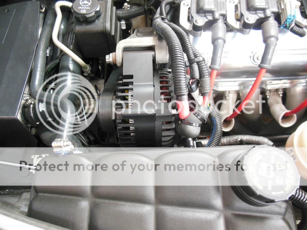
I had low voltage at idle with the air on because of the underdrive pulley, got a Billet Tech alternator, came complete and solved my issues.The Denso guts are far superior to the Valeo, but then again, it costs twice as much.
03-28-2015, 10:45 AM
#11
Racer
Thread Starter
Thanks for your replies, you have provided excellent information and made things a bit easier. Yesterday it was in the 40's here and I was really thinking spring, today its snowing like hell, I lost all my ambition and the alternator can wait. Crap the snow plows are out.
03-28-2015, 02:16 PM
#12

What is mentioned is basically enough to get the job done.
IMO, do it once and be done with it. I don't have sound system or under drive pulley, just enjoy seeing I have steady 14.4 at idle, 14.7 cruising and ignition is getting full juice while sparking.
Here is what I did. Start with a simple understanding of materials - google was my friend.
1. I used Cross Link insulated 1/0 gauge. One additional + from alternator to battery with an inline fuse and an addition ground - some call that a +3 concept.

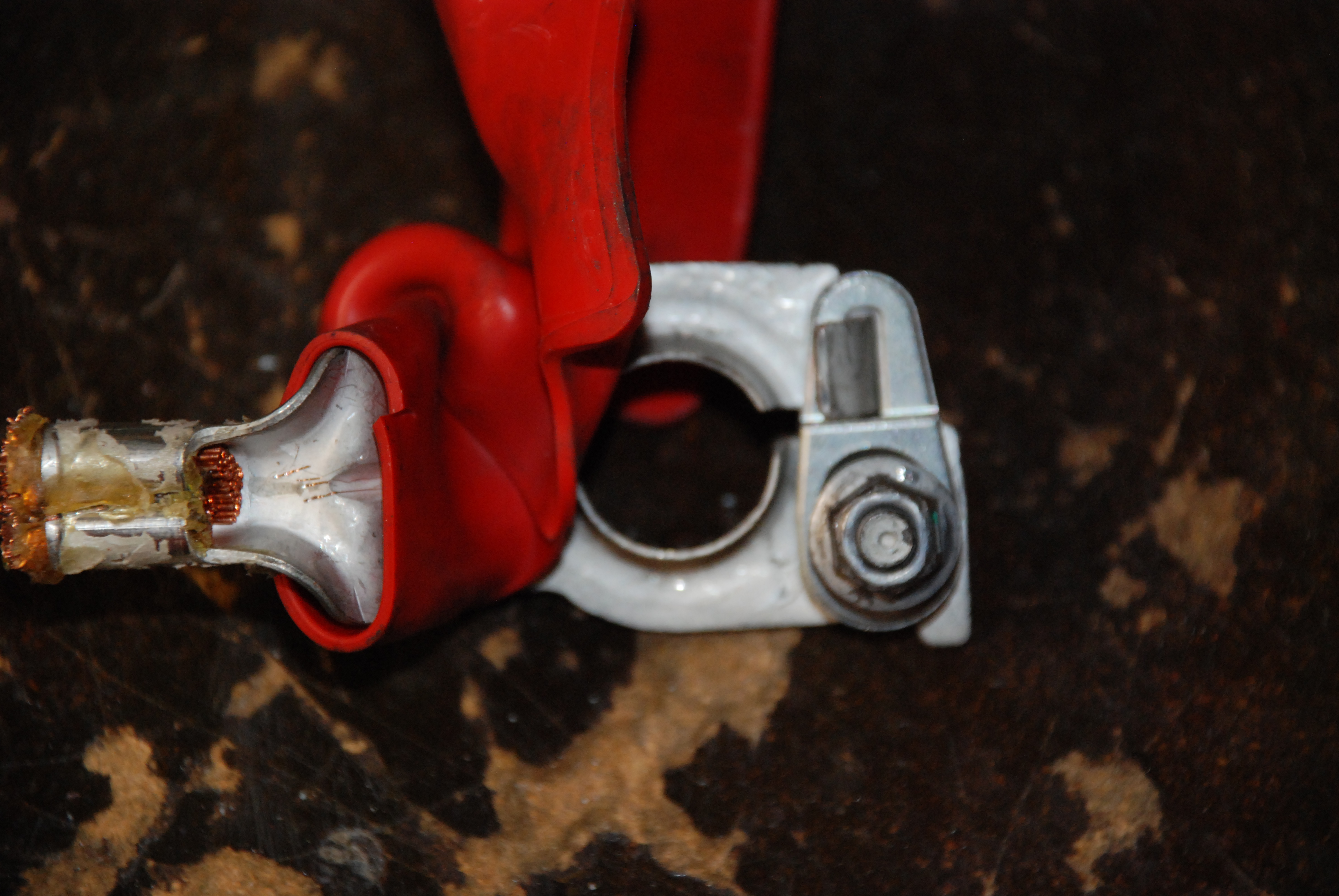
2. Used marine grade tinned terminals(picture has one copper for comparison), machined nylon wire transition piece and made crimping tool(not shown):

3. Use Tsunami battery terminal, made one piece terminal adapter, one end machine bored to fit 1/0 gauge and the other solid end precisely fit into the Tsunami and both end, used set screw to secured.

4. Used marine grade heat shrink, double, at every joint, as well as self vulcanizing silicone tape to isolate from environment for an air tight fit, to avoid copper wire corrosion.
5. Cover with Marine grade, cross link split loom and self vulcanizing silicone tape to protect all new wires.
IMO, got to use the right components to avoid gremlins down the line.
Feel free to ask, if there is any question.

IMO, do it once and be done with it. I don't have sound system or under drive pulley, just enjoy seeing I have steady 14.4 at idle, 14.7 cruising and ignition is getting full juice while sparking.
Here is what I did. Start with a simple understanding of materials - google was my friend.
1. I used Cross Link insulated 1/0 gauge. One additional + from alternator to battery with an inline fuse and an addition ground - some call that a +3 concept.
2. Used marine grade tinned terminals(picture has one copper for comparison), machined nylon wire transition piece and made crimping tool(not shown):
3. Use Tsunami battery terminal, made one piece terminal adapter, one end machine bored to fit 1/0 gauge and the other solid end precisely fit into the Tsunami and both end, used set screw to secured.
4. Used marine grade heat shrink, double, at every joint, as well as self vulcanizing silicone tape to isolate from environment for an air tight fit, to avoid copper wire corrosion.
5. Cover with Marine grade, cross link split loom and self vulcanizing silicone tape to protect all new wires.
IMO, got to use the right components to avoid gremlins down the line.
Feel free to ask, if there is any question.
03-28-2015, 02:30 PM
#13
Race Director
Member Since: Aug 2005
Location: Hudson WI
Posts: 13,598
Received 181 Likes
on
162 Posts
NCM Sinkhole Donor
So, victorf, you ran a wire from the alternator to the battery with a fuse and updated the terminal ends, correct?
Couple questions, what size cable did use from the alternator to the battery and where did you get the fuse?
Thanks!
Couple questions, what size cable did use from the alternator to the battery and where did you get the fuse?
Thanks!
03-28-2015, 04:41 PM
#14
Generally, bigger is better, but I had some high quality 1/0 gauge with cross link constructed insulation from previous projects, saved for special occasions. Fuse is Scorpion Brand, but I forgot the online audio supply company's name. I just googled and bought, including shipping, from the least expensive company.
FYI, T6 mounting bracket with stand offs under the fuse is homemade:

Additional FYI: I don't solder my battery wire connections, beside acid in solder leads to adverse chemical effects on copper wire, high heat from soldering leads to degradation to wire insulation. To avoid compromising joint connections, I used only mechanical crimping method and double sleeve with cross link marine grade heat shrink with adhesive as an environmental barrier.
YMMV.
Last edited by victorf; 03-28-2015 at 04:55 PM.
03-29-2015, 03:59 AM
#15
Got to say, Digging the condition 3 redundant wire idea!!!!
If the starter solenoid goes south from header heat, you still have a cable to the battery to keep the battery charging. The starter won't work, but at least you could push start a manual car. Just hold the start button to put the car in run mode, then bump start the car.
The only thing I would change is the 100 amp, since 1/0 gauge wire can carry a 150 amp load, and would change the fuse out to 150 amp instead.