
[Z06] Some pretty basic C6 suspension geometry questions...
 08-29-2012, 12:01 PM
#1
Cruising

Thread Starter

Member Since: Aug 2012
Posts: 12
Likes: 0
Received 0 Likes
on
0 Posts
Hello everyone. I'm new. I should say that I'm new to the Corvette forum but not the world of cars or internet forums. A little introdcution and background...
My name is Charlie, I'm a Mechanical Engineer and designer. Sadly, like most Mechie's I don't get to do car stuff in my job, so I have to do it at home on my own time. To satisfy my "jones" for tech and cars, I design cars. At the moment I am putting together a mid engine carbon fiber monocoque chassis that will run on C6 suspension and ZR1 wheels/tires/brakes. Drivetrain will be LS3 or LS7 twin turbo through an Albins AGB10 gearbox.
Here's my current difficulty. I talked to the Tech Transfer people and SEMA and because I'm not manufacturing parts for Corvette owners to buy, GM will not share the CAD files with me so I have to model the suspension components myself. I'm not a Vette guy so I'm not intimately familar with the differences from year to year and trim level to trim level and I don't have example parts. There is a lot of information on the webs but as with anything much of it is either unreliable or contradictory. So I have questions for the Gurus...
1. Is the geometry of the pick up points on the frame from C5 to C6 the same? Is it the same from base C6 to C6Z06? Suspension Analyzer V2.4 has a 2001 vette file in its library. If the position of the pick up points is the same I can use that information to locate the control arm pivot points and balljoints in space which will really help alot.
2. I know there are differences in material and manufacturing process etc., but are the C5 and C6 control arms dimensionally different? I can probably find some older C5 pieces at a junk yard here to give me something to model from.
3. Are the base C6 and C6Z06 rear upper control arms the same. I know that the Z06 uses tie bars where the base C6 does not, but are the arms dimensionally the same?
4. Does anyone have dimensioned diagrams of the C6 control arms that they would be willing to furnish me with? A have models of the spindles and ball joints that I found floating around the web, and I can do what needs to be done without actual models of the control arms, but I would like to model them and if someone already has the dimensions it would save me a lot of work.
I want to use C6 Z06 parts in my build because I want to use the tie bar design front and back, but it would really be a downer if I design something based on the information that I have and find out that there are minor, or major differences.
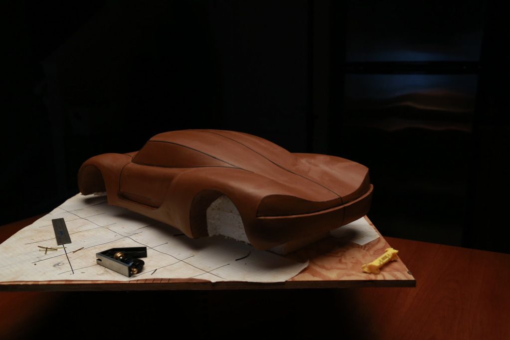
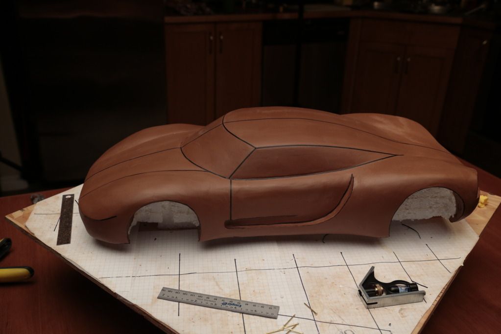
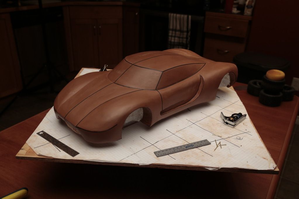
Here's a couple of pics of the clay model. It's still a bit rough but you can see where it's going. The front end and the door cutaway has been revised a bit since these pics were done.
thanks very much for any help you can offer me.
Charlie
My name is Charlie, I'm a Mechanical Engineer and designer. Sadly, like most Mechie's I don't get to do car stuff in my job, so I have to do it at home on my own time. To satisfy my "jones" for tech and cars, I design cars. At the moment I am putting together a mid engine carbon fiber monocoque chassis that will run on C6 suspension and ZR1 wheels/tires/brakes. Drivetrain will be LS3 or LS7 twin turbo through an Albins AGB10 gearbox.
Here's my current difficulty. I talked to the Tech Transfer people and SEMA and because I'm not manufacturing parts for Corvette owners to buy, GM will not share the CAD files with me so I have to model the suspension components myself. I'm not a Vette guy so I'm not intimately familar with the differences from year to year and trim level to trim level and I don't have example parts. There is a lot of information on the webs but as with anything much of it is either unreliable or contradictory. So I have questions for the Gurus...
1. Is the geometry of the pick up points on the frame from C5 to C6 the same? Is it the same from base C6 to C6Z06? Suspension Analyzer V2.4 has a 2001 vette file in its library. If the position of the pick up points is the same I can use that information to locate the control arm pivot points and balljoints in space which will really help alot.
2. I know there are differences in material and manufacturing process etc., but are the C5 and C6 control arms dimensionally different? I can probably find some older C5 pieces at a junk yard here to give me something to model from.
3. Are the base C6 and C6Z06 rear upper control arms the same. I know that the Z06 uses tie bars where the base C6 does not, but are the arms dimensionally the same?
4. Does anyone have dimensioned diagrams of the C6 control arms that they would be willing to furnish me with? A have models of the spindles and ball joints that I found floating around the web, and I can do what needs to be done without actual models of the control arms, but I would like to model them and if someone already has the dimensions it would save me a lot of work.
I want to use C6 Z06 parts in my build because I want to use the tie bar design front and back, but it would really be a downer if I design something based on the information that I have and find out that there are minor, or major differences.
Here's a couple of pics of the clay model. It's still a bit rough but you can see where it's going. The front end and the door cutaway has been revised a bit since these pics were done.
thanks very much for any help you can offer me.
Charlie
 08-30-2012, 11:54 AM
#3
Team Owner


All the mounting points/etc are the same on any c6. That is about as much help as I can provide. I would maybe contact the guys at LG. They are probably the best place for good suspension info on c6s.
 09-06-2012, 05:43 PM
#5
Cruising
Thread Starter
Member Since: Aug 2012
Posts: 12
Likes: 0
Received 0 Likes
on
0 Posts
That is a 1/7th model. It's an odd scale but I wanted to have wheels for better visual affect and the only ones I could find were these 4" ones which are still a bit oversized. I'm still not happy with the proportion of the front end. At the moment I'm concentrating on the suspension and modeling the subframes but one of my next key steps is to get the body modeled in Alias.
Thanks for your compliment.
Thanks for your compliment.
Last edited by Wytbishop; 01-29-2013 at 11:45 AM.
09-06-2012, 07:58 PM
#6
Drifting


I am not sure what you actually mean by the Z06 having "Tie bar" suspension. They are unequal length a-arms with the rear uprights having a toe link. Same as all C6 Vettes. Since you want to use C6 suspension anyway, my suggestion is to hit a junk yard and buy the complete suspension a-arms, uprights, rear toe links and steering rack. That way you can measure them and design your frame to fit the geometry. You will need to know tire sizes and offsets before you finalize wheel well configuations anyway. I think that once you have parts in hand, with your background, the mystery will fade quickly.
Gary
Gary
09-06-2012, 08:30 PM
#7
Le Mans Master


1. Is the geometry of the pick up points on the frame from C5 to C6 the same?
Essentially to exactly.
Is it the same from base C6 to C6Z06?
Absolutely.
Suspension Analyzer V2.4 has a 2001 vette file in its library. If the position of the pick up points is the same I can use that information to locate the control arm pivot points and balljoints in space which will really help alot.
You can also crawl up under a C6 take some pictures (on a lift is easier), and then arrange the control arms you build to have the same angles as the ones in a real car. This will get you into the 1/100dth inch range of dimensional accuracy which is fine for modeling.
2. I know there are differences in material and manufacturing process etc., but are the C5 and C6 control arms dimensionally different?
Essentially not. That is they are essentially the same.
3. Are the base C6 and C6Z06 rear upper control arms the same.
Absolutely.
4. Does anyone have dimensioned diagrams of the C6 control arms that they would be willing to furnish me with?
I do not.
I want to use C6 Z06 parts in my build because I want to use the tie bar design front and back, but it would really be a downer if I design something based on the information that I have and find out that there are minor, or major differences.
At 1/7th scale any dimensional differences will be less than a fraction of a millimeter.
09-07-2012, 02:13 PM
#8
Cruising
Thread Starter
Member Since: Aug 2012
Posts: 12
Likes: 0
Received 0 Likes
on
0 Posts
I am not sure what you actually mean by the Z06 having "Tie bar" suspension. They are unequal length a-arms with the rear uprights having a toe link. Same as all C6 Vettes. Since you want to use C6 suspension anyway, my suggestion is to hit a junk yard and buy the complete suspension a-arms, uprights, rear toe links and steering rack. That way you can measure them and design your frame to fit the geometry. You will need to know tire sizes and offsets before you finalize wheel well configuations anyway. I think that once you have parts in hand, with your background, the mystery will fade quickly.
Gary
Gary
I'm trying to avoid buying parts if I can help it. I will be using ZR1 wheels/tires/brakes etc and when the time comes I will buy new parts, but for now it would be more convenient obviously to have diagrams. Also junk yard C6 vettes are not easily come by up in my neck of the woods.
I have modeled the wheels and tires and I have models of the uprights. The only thing I really need to be absolutley sure of before I go too much further is the precise location of the C6Z control arm pivot points.
I appreciate your help.
10-14-2012, 08:15 PM
#10
Cruising
Thread Starter
Member Since: Aug 2012
Posts: 12
Likes: 0
Received 0 Likes
on
0 Posts
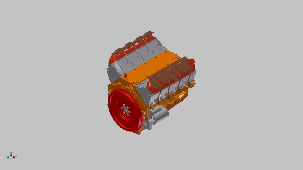
Progress continues buy slowly. I managed to find a professional model of the LS3 engine and have been working on the rear subframe for several weeks now. I've been through a few iterations now and I believe I have it.
I will post a couple of renderings later.
I will post a couple of renderings later.
10-14-2012, 09:58 PM
#11


[...] To satisfy my "jones" for tech and cars, I design cars. At the moment I am putting together a mid engine carbon fiber monocoque chassis that will run on C6 suspension and ZR1 wheels/tires/brakes. Drivetrain will be LS3 or LS7 twin turbo through an Albins AGB10 gearbox. [...]

Way cool project, Charlie. Sorry I don't have anything to offer other than encouragement.
10-26-2012, 10:58 AM
#12
Instructor
I am in the process of modeling the C6 rear suspension and can tell you that the suspension analyzer data for the C5 rear suspension is not the same as C6 rear.Good luck with your project.
12-24-2012, 10:52 AM
#13
Cruising
Thread Starter
Member Since: Aug 2012
Posts: 12
Likes: 0
Received 0 Likes
on
0 Posts
Hey everyone, a little update. I have been working on modeling the rear subframe and suspension for about 4 months now. It's sort of like sculpting in digital 3D space.
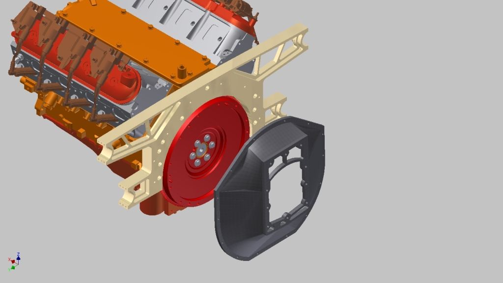
I purchased a professional model of the LS3 engine...
...and Albins, the maker of the gearbox I spec'd for the project sent me some dimensioned drawings of their gearbox from which I made a fairly crude model...
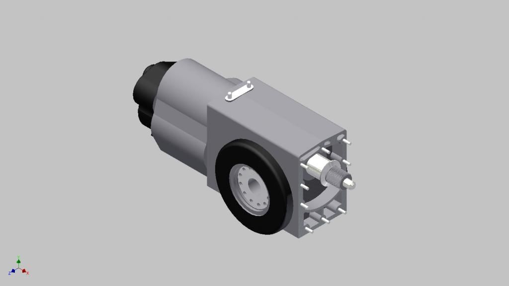
The first part I made was the adaptor plate and bellhousing that would connect the gearbox to the engine. This is a two piece concept and the adaptor plate is actually going to be the mounting point of the tubular subframe...
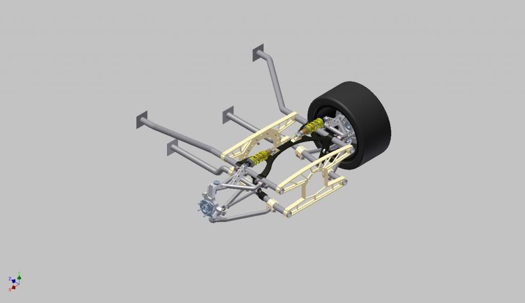
Here is the basic subframe with all the control arm mounts...
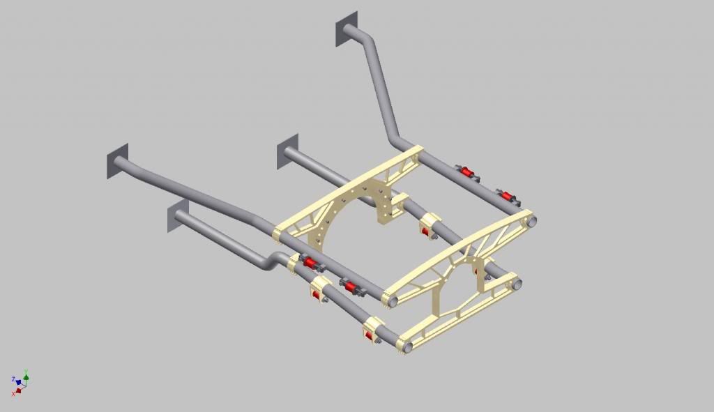
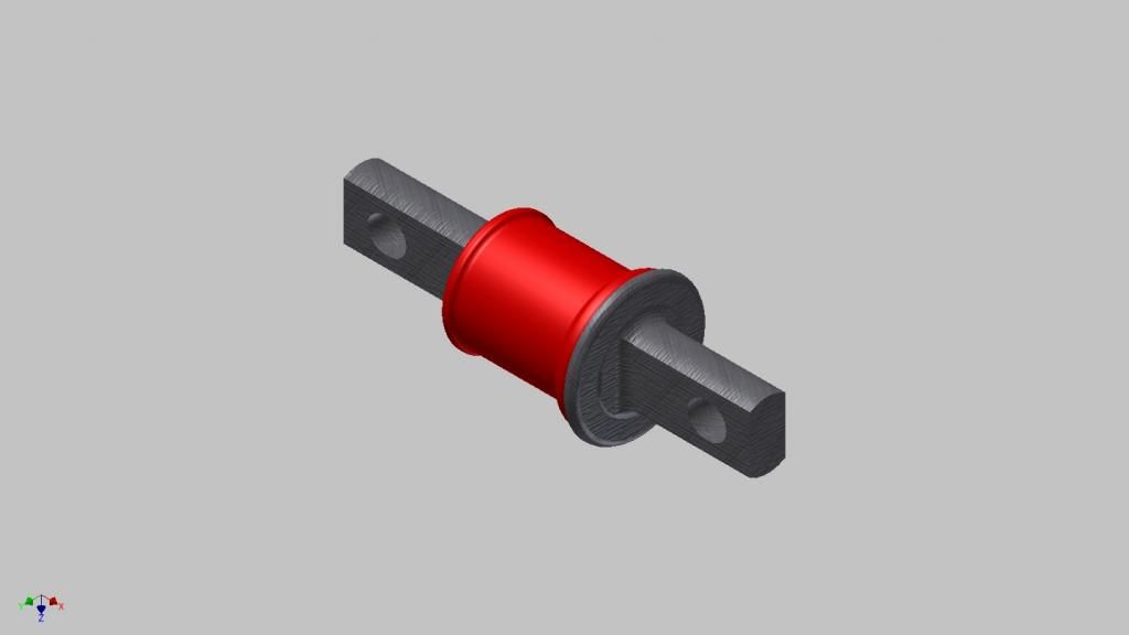
I modeled the corvette control arm bushings and position of all the control arm pivot points as they are given in the Suspension Analyzer software.
Next I position the Corvette uprights and modeled some wheels to ZR1 specs and positioned the upper and lower ball joints and designed the upper and lower control arms. They are very close to Corvette dimensions but not exactly as my car will have a slightly wider track. I decided on a cam activation system for the coilover shocks...
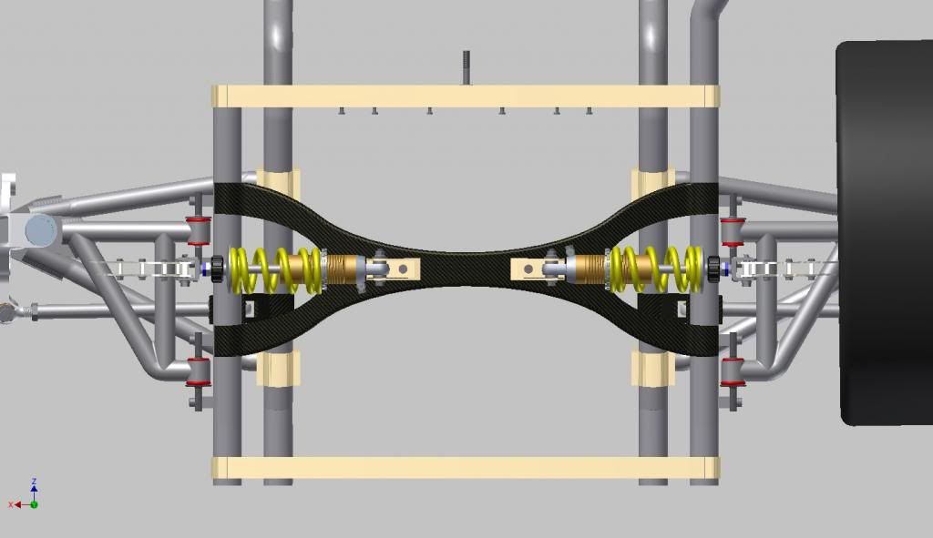
I got ahold of a model of an Ohlins shock which is very close to the shock I will be using and modeled a mounting member which traverses the subframe overtop the gearbox. This provides a mount for the shocks and also significantly stiffens the subframe...
The hardest part so far has been identifying the pivot point of the rear toe link. I assembled the suspension and moved the upright through it's full travel plotting the position of the outer rod end at multiple points. Then I drew a curve in 3D space that corresponds to those points and found the center point of that curve.
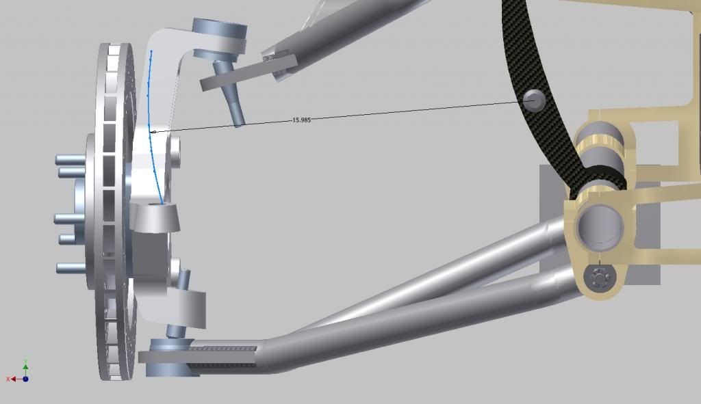
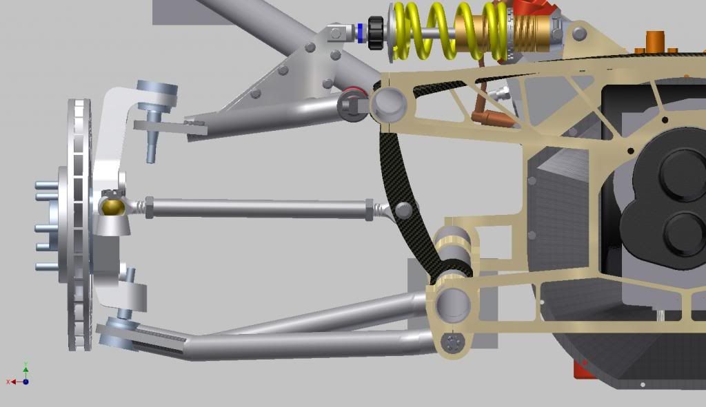
That is the position of the inner tie rod end. From there I modeled a mount for it, which again adds stiffness to the subframe and a tie rod to link the upright to the frame and I get this...
...at ride height...
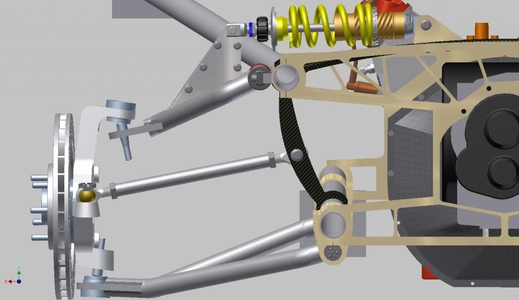
...at full sag...
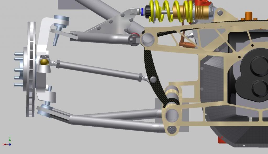
...and at full bump...
So that's where I am at the moment. But I have a question for the group.
What is the stock suspension travel from normal ride height to full compression of a C6 Z06 or ZR1?
Mine will not be exactly the same but I want to do some calculations of geometry and strength at various suspension positions and I want to make sure im in the ballpark of where the true compression position will be. Sure it looks cool, but I want to make sure it's goign to be strong enough in a 1G corner.
Thanks for any of your help. Your opinions are always welcome.
Charlie
I purchased a professional model of the LS3 engine...
...and Albins, the maker of the gearbox I spec'd for the project sent me some dimensioned drawings of their gearbox from which I made a fairly crude model...
The first part I made was the adaptor plate and bellhousing that would connect the gearbox to the engine. This is a two piece concept and the adaptor plate is actually going to be the mounting point of the tubular subframe...
Here is the basic subframe with all the control arm mounts...
I modeled the corvette control arm bushings and position of all the control arm pivot points as they are given in the Suspension Analyzer software.
Next I position the Corvette uprights and modeled some wheels to ZR1 specs and positioned the upper and lower ball joints and designed the upper and lower control arms. They are very close to Corvette dimensions but not exactly as my car will have a slightly wider track. I decided on a cam activation system for the coilover shocks...
I got ahold of a model of an Ohlins shock which is very close to the shock I will be using and modeled a mounting member which traverses the subframe overtop the gearbox. This provides a mount for the shocks and also significantly stiffens the subframe...
The hardest part so far has been identifying the pivot point of the rear toe link. I assembled the suspension and moved the upright through it's full travel plotting the position of the outer rod end at multiple points. Then I drew a curve in 3D space that corresponds to those points and found the center point of that curve.
That is the position of the inner tie rod end. From there I modeled a mount for it, which again adds stiffness to the subframe and a tie rod to link the upright to the frame and I get this...
...at ride height...
...at full sag...
...and at full bump...
So that's where I am at the moment. But I have a question for the group.
What is the stock suspension travel from normal ride height to full compression of a C6 Z06 or ZR1?
Mine will not be exactly the same but I want to do some calculations of geometry and strength at various suspension positions and I want to make sure im in the ballpark of where the true compression position will be. Sure it looks cool, but I want to make sure it's goign to be strong enough in a 1G corner.
Thanks for any of your help. Your opinions are always welcome.
Charlie
01-23-2013, 01:12 PM
#14
Cruising
Thread Starter
Member Since: Aug 2012
Posts: 12
Likes: 0
Received 0 Likes
on
0 Posts
I have been working on perfecting the rear subframe. Making sure there are no interferences etc. The design is nearly perfect in terms of fitting my vision and the functionality I want.
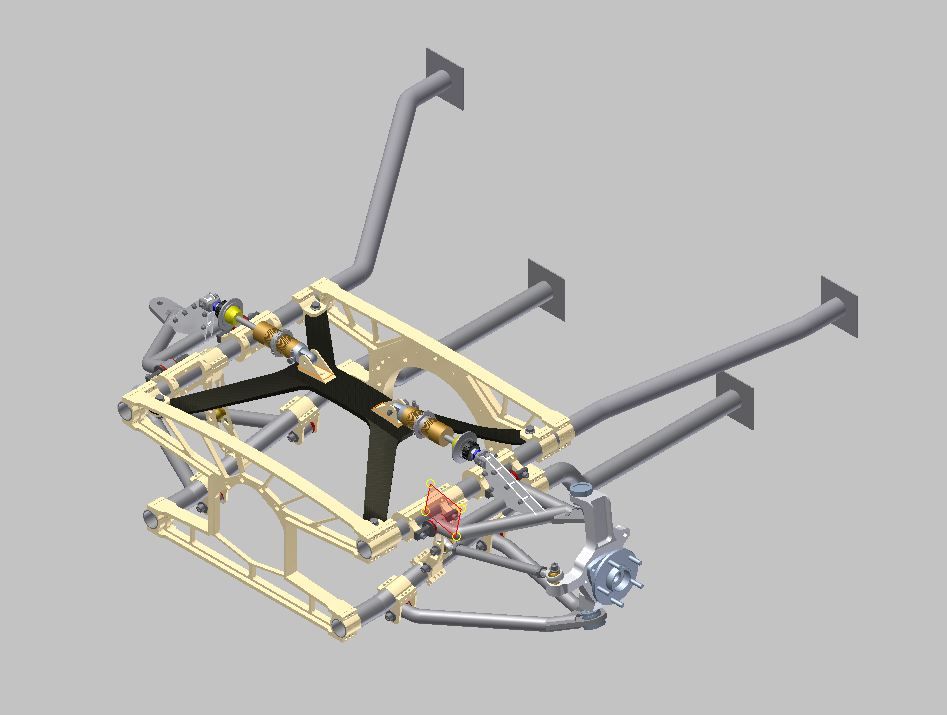
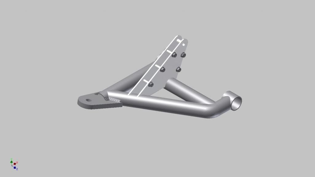
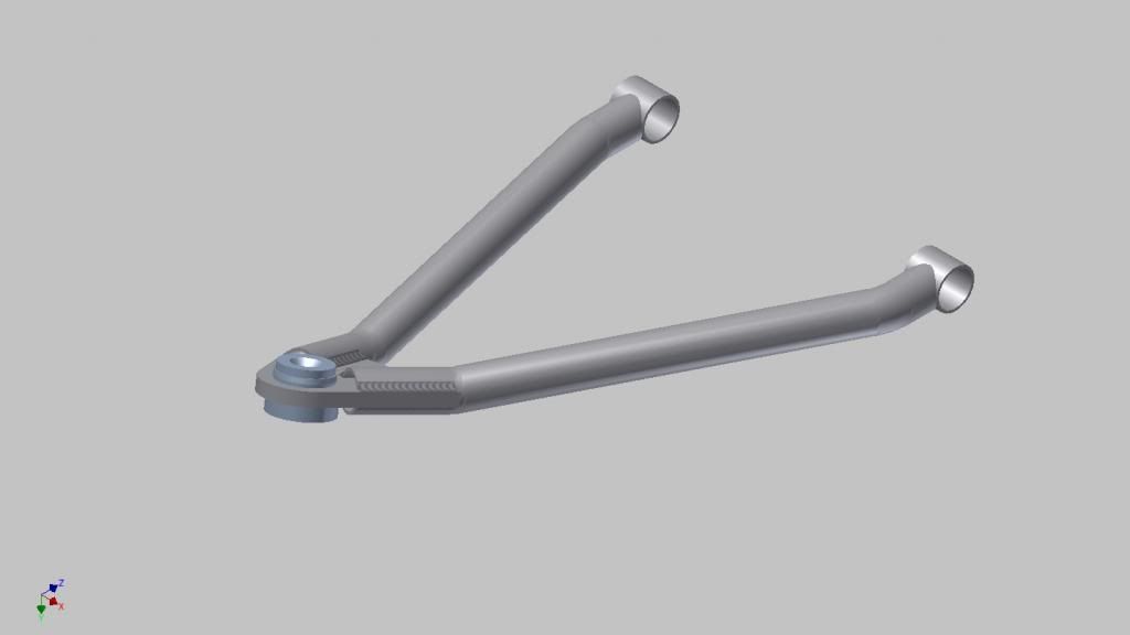
The strut that secures the toe link in the rear.
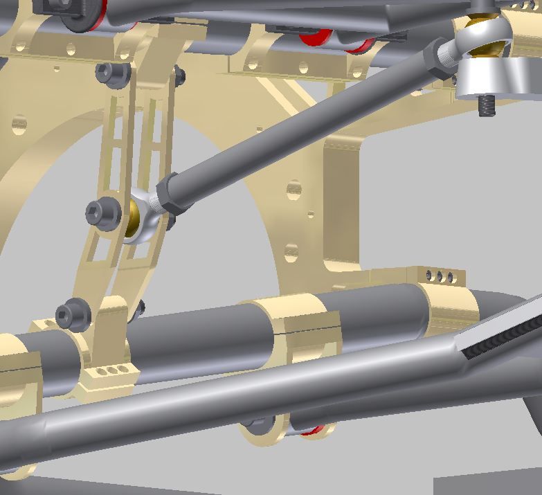
The upper control arm tie bars.
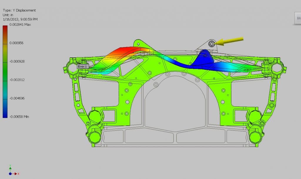
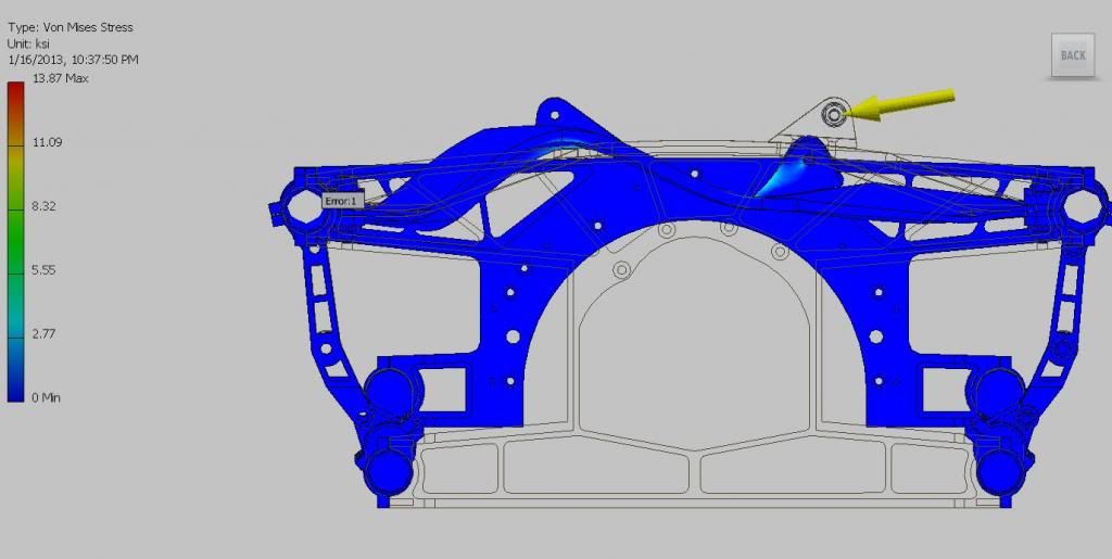
I have now started FEA on some parts of the model.
In this view I'm applying a 1000lb force to the boss where the shock is secured to determine the stress generated in the shock mount and the deflection of the part. The blue parts are the maximum deflection in the -ve "Y" axis of 0.00658"...so that's pretty good I think. This is all new to me so I'm still learning how to accurately perform these simulations and interpret the results.
This view shows the stress generated in the same part under the same loading. The maximum stress is in the shock mount boss is very small...under 3000psi.
I have started laying out the front end but it's tricky because I don't have accurate models of things like the rad I would use or the steering rack...stuff like that has to be located in order to determine how much space you have. I know the starting points of the C5/6 suspension components and roughly where the fuel cell will be and so on but it's going to be much tricker than the rear was i think.
I'm also spending a lot of time reading about suspension design and learning how to use the FEA component of the modeling software...so there's no shortage of things to do.
Anyway...hope people are still moderately interested. i appreciate the feedback and offers of help I have receieved.
Charlie
The strut that secures the toe link in the rear.
The upper control arm tie bars.
I have now started FEA on some parts of the model.
In this view I'm applying a 1000lb force to the boss where the shock is secured to determine the stress generated in the shock mount and the deflection of the part. The blue parts are the maximum deflection in the -ve "Y" axis of 0.00658"...so that's pretty good I think. This is all new to me so I'm still learning how to accurately perform these simulations and interpret the results.
This view shows the stress generated in the same part under the same loading. The maximum stress is in the shock mount boss is very small...under 3000psi.
I have started laying out the front end but it's tricky because I don't have accurate models of things like the rad I would use or the steering rack...stuff like that has to be located in order to determine how much space you have. I know the starting points of the C5/6 suspension components and roughly where the fuel cell will be and so on but it's going to be much tricker than the rear was i think.
I'm also spending a lot of time reading about suspension design and learning how to use the FEA component of the modeling software...so there's no shortage of things to do.
Anyway...hope people are still moderately interested. i appreciate the feedback and offers of help I have receieved.
Charlie
01-23-2013, 10:23 PM
#15
Instructor

Member Since: Jan 2010
Location: Palm Bay FL
Posts: 128
Likes: 0
Received 0 Likes
on
0 Posts
Have you read the books from this guy?
http://www.carrollsmith.com/books/
I have the rear of my z06 on jack stands right now (getting new rubber), I'll measure the suspension droop vs. ride height tomorrow night.
Mesh density small enough to get 3 element through thickness on 3d parts?
I'd put something like a FoS of 4 to yielding on the suspension parts. Maybe someone can chime in on how to get the dynamic loads or at least something to help get you started with a g factor against static loads. I'm guessing this would be ALOT like 4-8 g's.
My opinion is that buying a wrecked/used complete car would probably save you money in the long run on this project. Maybe I'm just being tired and cranky after a rough day.
01-24-2013, 02:05 AM
#16
Cruising
Thread Starter
Member Since: Aug 2012
Posts: 12
Likes: 0
Received 0 Likes
on
0 Posts
Have you read the books from this guy?
http://www.carrollsmith.com/books/
I have the rear of my z06 on jack stands right now (getting new rubber), I'll measure the suspension droop vs. ride height tomorrow night.
Mesh density small enough to get 3 element through thickness on 3d parts?
I'd put something like a FoS of 4 to yielding on the suspension parts. Maybe someone can chime in on how to get the dynamic loads or at least something to help get you started with a g factor against static loads. I'm guessing this would be ALOT like 4-8 g's.
My opinion is that buying a wrecked/used complete car would probably save you money in the long run on this project. Maybe I'm just being tired and cranky after a rough day.
http://www.carrollsmith.com/books/
I have the rear of my z06 on jack stands right now (getting new rubber), I'll measure the suspension droop vs. ride height tomorrow night.
Mesh density small enough to get 3 element through thickness on 3d parts?
I'd put something like a FoS of 4 to yielding on the suspension parts. Maybe someone can chime in on how to get the dynamic loads or at least something to help get you started with a g factor against static loads. I'm guessing this would be ALOT like 4-8 g's.
My opinion is that buying a wrecked/used complete car would probably save you money in the long run on this project. Maybe I'm just being tired and cranky after a rough day.
I'm seriously just learning how to use FEA. I'm not an Engineer, I'm an Engineering Technologist and we don't get a lot of education with tools like that. So although I am well versed in the physics, I have no experience with the anaysis tools. I'm looking for more literature on the use of FEA and the interpretation of the results.
01-28-2013, 12:07 PM
#17
5th Gear

Member Since: Nov 2012
Posts: 5
Likes: 0
Received 0 Likes
on
0 Posts
You need to determine the dynamic forces associated x amount of g forces at the same time for braking, in a turn with a x amount of g in bump. This would be your worst case scenerio. You can seperate them out by each varible to see how each is affecting the loading seperately but to do a ultimate and final analysis all three must be done at the same time.
Another thing is don't consider only ultimate yield but deflection. This is for two reasons. One any deflection will compromise the geometry because things will move in a unpredicable manner making any adjustments a nightmare. The second reason is fatigue. Fatigue is caused by the flexing of the parts but most importantly how the deflection if any is distributed along the part. You will want it to deflect uniformly between the force input points. Cycle life of a part is greatly reduced if the deflection is not uniform and concentrated in small areas.
This goes for chassis. Divide the chassis into three distinct groups. Front, Middle and Rear subframe. You don't want any one group having more or less deflection than the rest. This increases the fatigue stresses at the connections of the subframes. Also you want to look at the deflections per unit length over the entire chassis length. You want to keep the same deflection per foot or whatever you choose to be the same.
One more thing. I would also input any stresses caused by fasteners. especially if you are close to the limits of stresses within the part. If you are way ahead of the forces usually you are ok but I always add all of the forces this will eliminate any unexpected issues.
Last edited by todd8541; 01-28-2013 at 12:10 PM.
01-28-2013, 12:26 PM
#18
5th Gear
Member Since: Nov 2012
Posts: 5
Likes: 0
Received 0 Likes
on
0 Posts
A few observations. I am not shooting your design down I think its a great project. However, I see alot of excess cost to you're project and potential failures or additinal weight to resolve issues.
One you have alot of billet pieces. If you decide to go that route I would take the material to a water jet and have them cut out as much of the profile as possible leaving enough material for machining clean up. This will reduce your machine time, and waste material. The "droppings" can be used to make other components such as brackets etc.
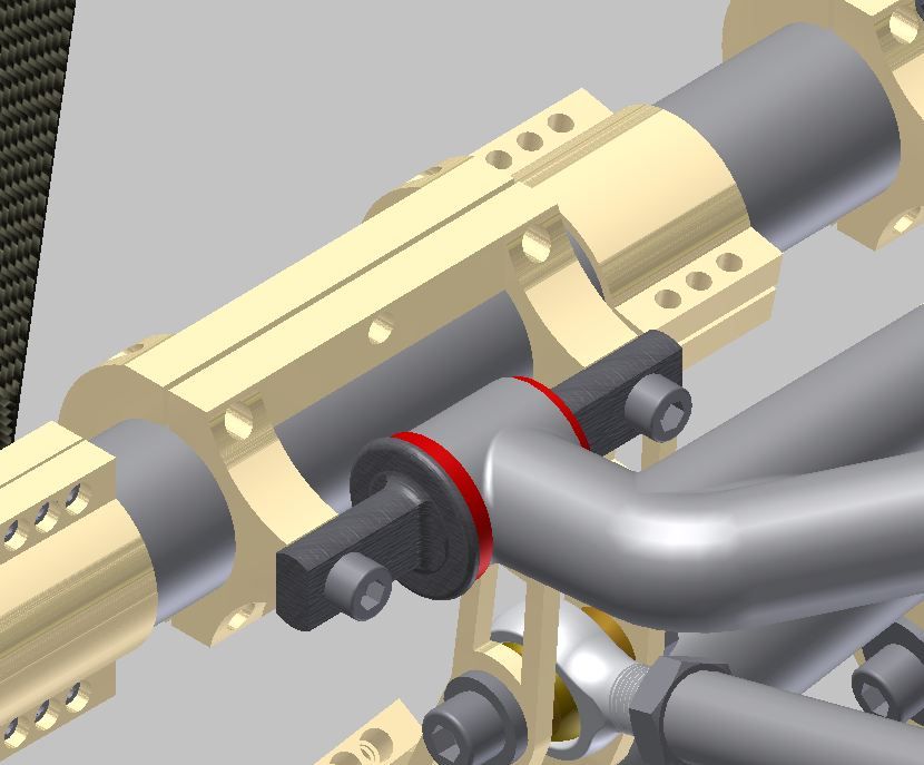
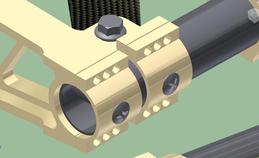
Another observation is you have alot of bolted joints. You will have to account of the "crush" of the tube where the bolted joints are. These will induce stres into the tubes reducing their load carring capacity. Plus you have alot of extra weight from the large amount of fasteners. Not counting the fact you have to ensure you have adequate clamp load. The best method is to measure bolt stretch which your design leaves you plenty of room to do so.
I would reconsider you're attachment method of your control arms to the tube frame structure. You are relying on a clamp load on the tube to counter act the forces and moments to maintain the correct positions. I think you'll find they will rotate about the tubes axis without sufficient clamp loads.
Again I am not shooting you're design down. I am just pointing out some things I see to help you from making costly and dangerous mistakes.
Good luck and keep posting updates I'd love to see how it progresses. When I actually get some time I will post my chassis also. Seems now my only free time is during lunch. Hopefully this weekend I'll have some progress.
One you have alot of billet pieces. If you decide to go that route I would take the material to a water jet and have them cut out as much of the profile as possible leaving enough material for machining clean up. This will reduce your machine time, and waste material. The "droppings" can be used to make other components such as brackets etc.
Another observation is you have alot of bolted joints. You will have to account of the "crush" of the tube where the bolted joints are. These will induce stres into the tubes reducing their load carring capacity. Plus you have alot of extra weight from the large amount of fasteners. Not counting the fact you have to ensure you have adequate clamp load. The best method is to measure bolt stretch which your design leaves you plenty of room to do so.
I would reconsider you're attachment method of your control arms to the tube frame structure. You are relying on a clamp load on the tube to counter act the forces and moments to maintain the correct positions. I think you'll find they will rotate about the tubes axis without sufficient clamp loads.
Again I am not shooting you're design down. I am just pointing out some things I see to help you from making costly and dangerous mistakes.
Good luck and keep posting updates I'd love to see how it progresses. When I actually get some time I will post my chassis also. Seems now my only free time is during lunch. Hopefully this weekend I'll have some progress.
01-28-2013, 05:37 PM
#19
Cruising
Thread Starter
Member Since: Aug 2012
Posts: 12
Likes: 0
Received 0 Likes
on
0 Posts
Todd, don't even worry about it. I appreciate the feedback. I have plenty of Physics and Engineering training but no experience so I'm always happy to hear from people who do.
I had actually already thought of a couple of your points. I have been working the last couple of days on repositioning the rear toe link to reduce the positive toe gain. Positioning the toe link on the lower control arm doesn't eleminate the toe change because the upright stays more or less vertical as the suspension travels. Moving the rod end to the lower side of the steering arm on the upright and recalculating the pivot point allowed me to get a much more accurate toe link position. I now have less than 0.25� static toe out and less than 0.5� toe out at full bump. The toe gain is very very small now but of course it's all adjustable with the toe link so I can zero it...or almost zero it if I need to.
As for clamping load you are absolutley right and my answer has been to add a fastener which will bisect the clamp and the tube. It won't add clamping force but it will contstrain rotation. I think I will also knurl the tubes at the points where the clamps will be applied.
I was concerned about weight and the number of fasteners, but I did some calculations and the total weight of all fasteners (in Titanium) is only about 16lbs. As far as cost, your point is a good one. I am not concerning myself with the cost of parts at all at this point. My estimates on the cost of off the shelf components is in the neibourhood of $75k. To make the molds and actually lay the carbon fiber parts I expect $50-70k more. Said and done I expect the cost estimate to reach $180k not including 1 minute of my time.
I'm still learning and reading regarding the correct loading in FEA. I don't fully understand it yet, so I appreciate your input on that. I have nothing really to add at this point.
01-28-2013, 07:05 PM
#20
5th Gear
Member Since: Nov 2012
Posts: 5
Likes: 0
Received 0 Likes
on
0 Posts
http://www.mrfracing.in/?page_id=59
The link shows the method i was describing. but in the end all that matters is you got it fixed. Seems like we both are doing an expensive project. I am not even going to think about the cost i am just going to do a part at a time and focus on the costs i can save. This way ill feel a little better about the cost.
One thing you do is if you bolted the brace that is on the end axially into the tube. you could machine a insert with a threaded boss and weld it into the tube and then bolt the brace to them. It would be stronger and less expensive. although there is always more than one way to skin a cat.
Be careful about using serrations on structural members. In certain instances they are great in others they can cause problems.
Just be careful in your design and always err on side of caution the last thing you want is for this to happen hahahaha