
DIY: LMR Breather Crankcase Gas Re-Route (No-Welding Option)
 03-28-2015, 08:59 PM
#1
Tech Contributor
Thread Starter
Member Since: Jan 2006
Location: Saint Louis MO
Posts: 4,761
Likes: 0
Received 219 Likes
on
110 Posts
St. Jude Donor '14-'15
Catchy name for a thread, huh? 
I have spent a few months in the off-season trying to perfect a DIY solution for the LMR breather re-routing issue, but specifically focused on a no-weld solution that was available to any average Joe. I also wanted to discharge the gases underneath the vehicle, as to not have them coming out of the scoop - after all, the problem of have the crankcase gases emerge through the driver's hood vent is only slightly moved forward with diverting to the main scoop.
In going through this process, I've ventured everywhere from cheap PVC angles to having custom CNC pieces made for silicone elbows. In the end, to truly be something that is DIY, everything needed to be freely available, and the tools required needed to be fairly standard.
I think I've finally nailed it, both in looks and overall availability and simplicity. I've eliminated any need for clamps in the system other than the first two, which is (in my opinion) both good-looking and convenient. Black main clamps instead of the stainless would be ideal, but I've taken long enough to get this up - no sense in delaying it further by nitpicking.
Let me know what you guys think - I'm not going to stick this in the How-To section for a few reasons. First, I'm not that vain. Really though, this is only for those of us using the LMR breather, so it doesn't exactly apply to everyone. I try to keep the How-To section related to stock modifications and information.
I'm posting the parts list in the next post, and then a walkthrough in a third post.
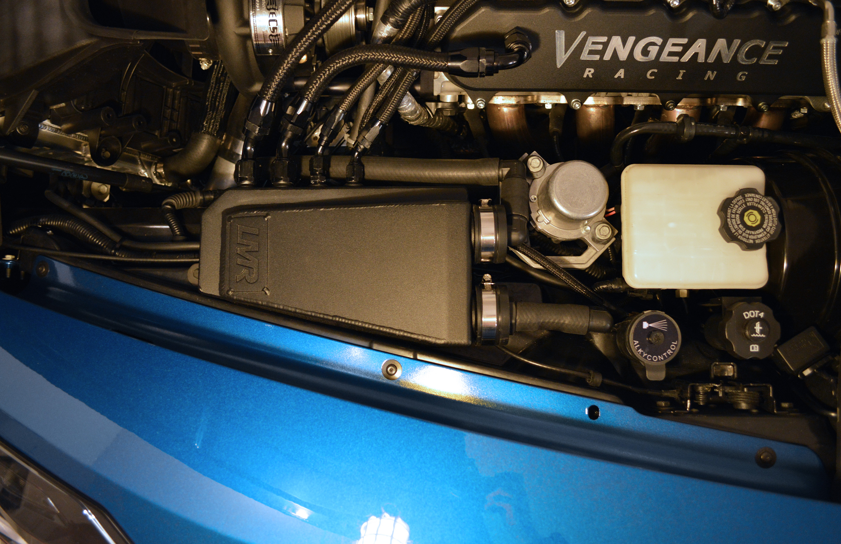
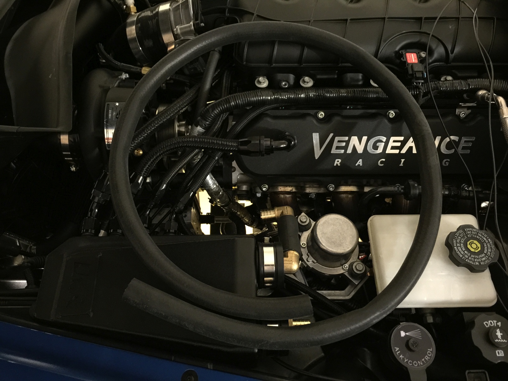
So, without making you read through two or three more posts to see the end result, I will post a picture of it right off the bat. If it's not your thing, at least you can skip reading ahead.
I have spent a few months in the off-season trying to perfect a DIY solution for the LMR breather re-routing issue, but specifically focused on a no-weld solution that was available to any average Joe. I also wanted to discharge the gases underneath the vehicle, as to not have them coming out of the scoop - after all, the problem of have the crankcase gases emerge through the driver's hood vent is only slightly moved forward with diverting to the main scoop.
In going through this process, I've ventured everywhere from cheap PVC angles to having custom CNC pieces made for silicone elbows. In the end, to truly be something that is DIY, everything needed to be freely available, and the tools required needed to be fairly standard.
I think I've finally nailed it, both in looks and overall availability and simplicity. I've eliminated any need for clamps in the system other than the first two, which is (in my opinion) both good-looking and convenient. Black main clamps instead of the stainless would be ideal, but I've taken long enough to get this up - no sense in delaying it further by nitpicking.
Let me know what you guys think - I'm not going to stick this in the How-To section for a few reasons. First, I'm not that vain.
Really though, this is only for those of us using the LMR breather, so it doesn't exactly apply to everyone. I try to keep the How-To section related to stock modifications and information.I'm posting the parts list in the next post, and then a walkthrough in a third post.
So, without making you read through two or three more posts to see the end result, I will post a picture of it right off the bat. If it's not your thing, at least you can skip reading ahead.
Last edited by Theta; 03-30-2015 at 04:02 AM.
 03-28-2015, 08:59 PM
#2
Tech Contributor
Thread Starter
Member Since: Jan 2006
Location: Saint Louis MO
Posts: 4,761
Likes: 0
Received 219 Likes
on
110 Posts
St. Jude Donor '14-'15
Tools Needed:
Flat-Head Screwdriver or 7mm Socket (To tighten hose clamps)
Heat Gun or >1200W Hairdryer (for softening rubber hose)
Tubing Cutter or Sharp Razor Blade(s) (for cutting hose)
3/4" Hole Saw / Spade Bit / Dremel (for cutting circular hole in cap #1)
1-1/4" Hole Saw / Spade Bit / Dremel (for cutting circular hole in cap #2)
(Optional) Black Spray Paint (for painting brass fittings - I used Rustoleum Pro Flat Black 15-min Dry)
(Optional) Painter's Tape (for painting brass fittings)
(Optional) Black Paint Pen (for coloring white silicone strands)
Parts List:
Lowes:
2 x American Valve 1-1/2-in Dia Flexible PVC Cap Fittings - Lowes Item #: 23490 | Model #: RPC40
(Plumbing Dept. - $2.90/ea) - $5.80
4 x Apollo 1-in Dia Brass PEX Elbow Crimp Fitting - Lowes Item #: 394257 | Model #: APXE11
(Plumbing Dept. - $4.29/ea) - $17.16
1 x Apollo 1-in x 1-in Barb Fitting - Item #: 314715 | Model #: APXMA11
(Plumbing Dept. - $5.65/ea) - $5.65
Gampak 2-Pack 1-in Rigid Lock Nuts - Item #: 75464 | Model #: 49103
(Electrical Dept. - $1.21/ea) - $1.21
AutoZone:
8ft ArmorMark 3/4" Heater Hose - Part Number: 50277 [Alternate Part Number: 65009]
(Behind counter - priced per foot @ $1.39 - 8ft is more than enough, and allows for mistakes.)
8 @ $1.39/ft = $11.12
eBay:
This is the exact part I used - as thickness of silicone tubes are frequently different, I'd recommend just using this and cutting off the small 1" sections.
$4.91 - http://www.ebay.com/itm/1-5-3-PLY-90...-/400513262758
Total Cost:
Lowes: $29.82
AutoZone: $11.12
eBay: $4.91
Final: $45.85
03-28-2015, 09:00 PM
#3
Tech Contributor
Thread Starter
Member Since: Jan 2006
Location: Saint Louis MO
Posts: 4,761
Likes: 0
Received 219 Likes
on
110 Posts
St. Jude Donor '14-'15
Note: If you end up liking the painted look of mine, skip down to the pain section before assembling the parts.
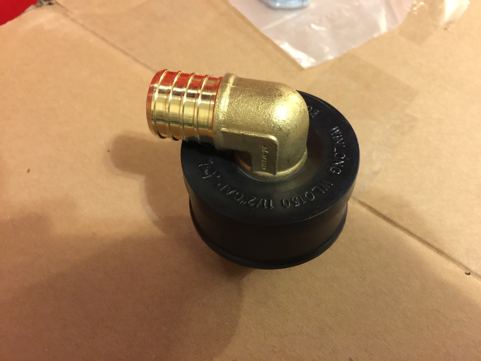
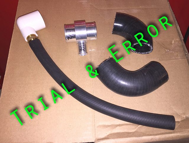
Start by removing the 1" by 1" male adapter from the package, as shown. Taking one of the 1.5" flexible pipe caps, and using either a drill press or drill, cut/drill a 1-1/4" hole in the center of the pipe cap. Refine the edge until the 1" x 1" adapter threads into the hole. Make sure it's still snug, as we're going to be using the material surrounding the adapter to clamp the pieces together using a steel conduit locknut, shown below.
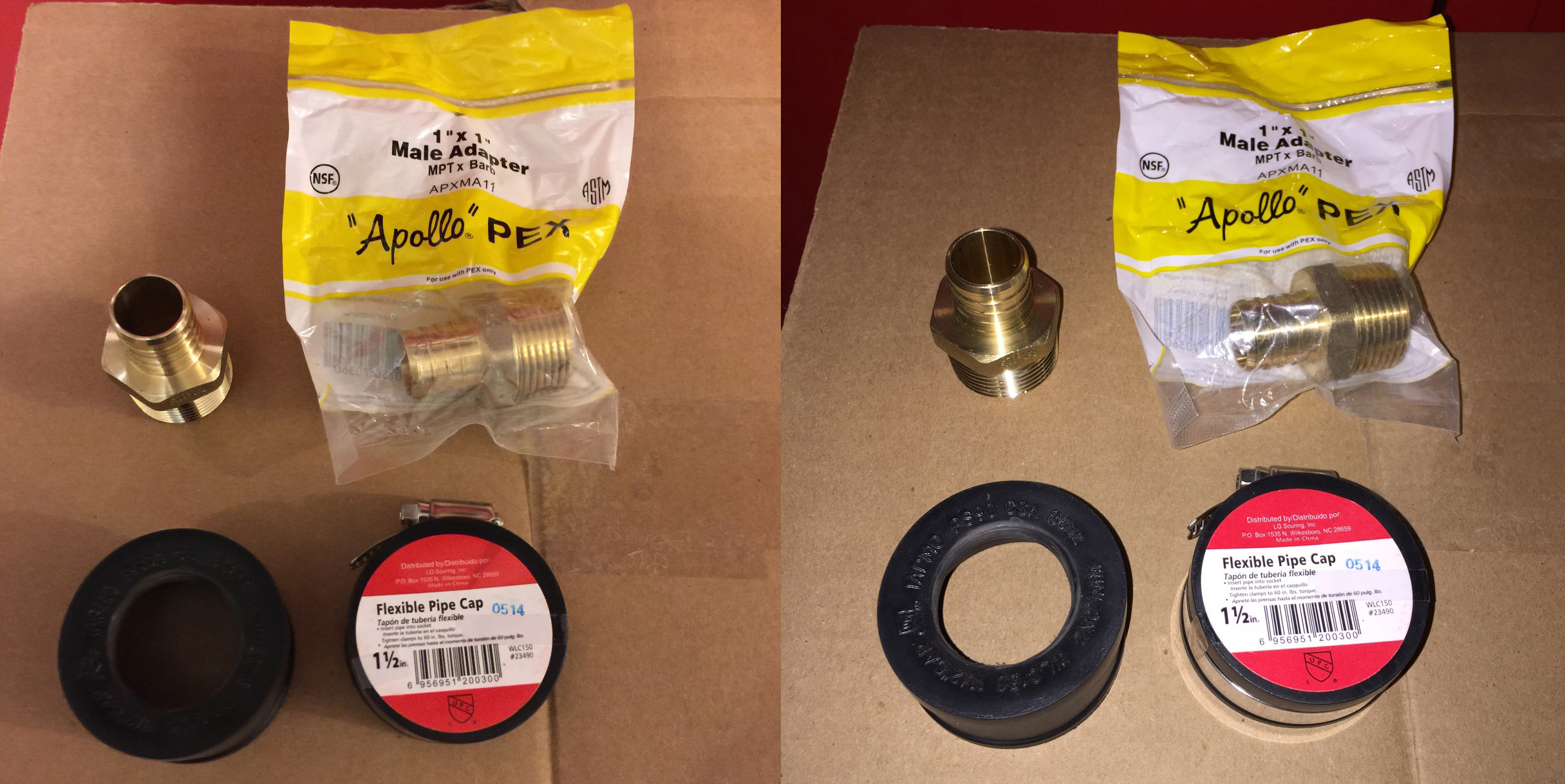
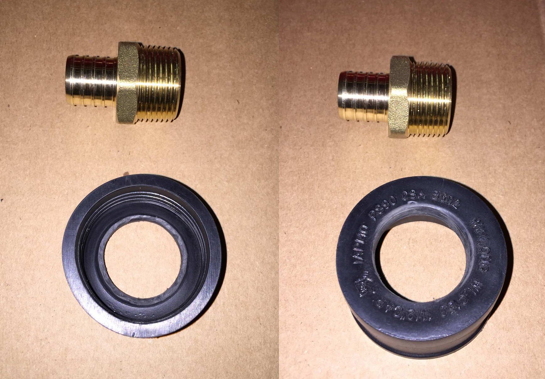
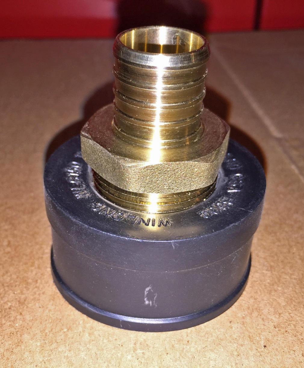
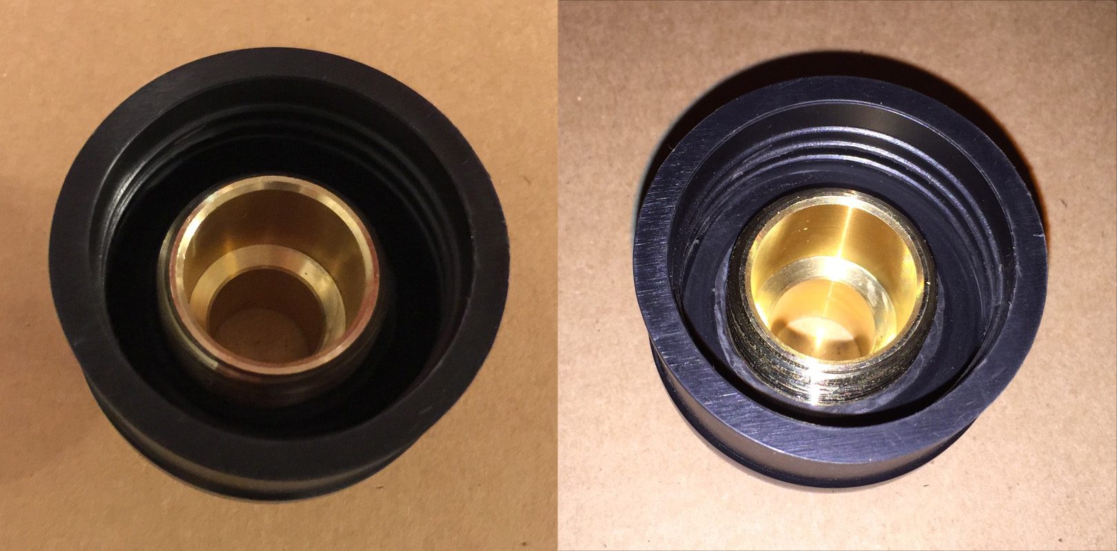
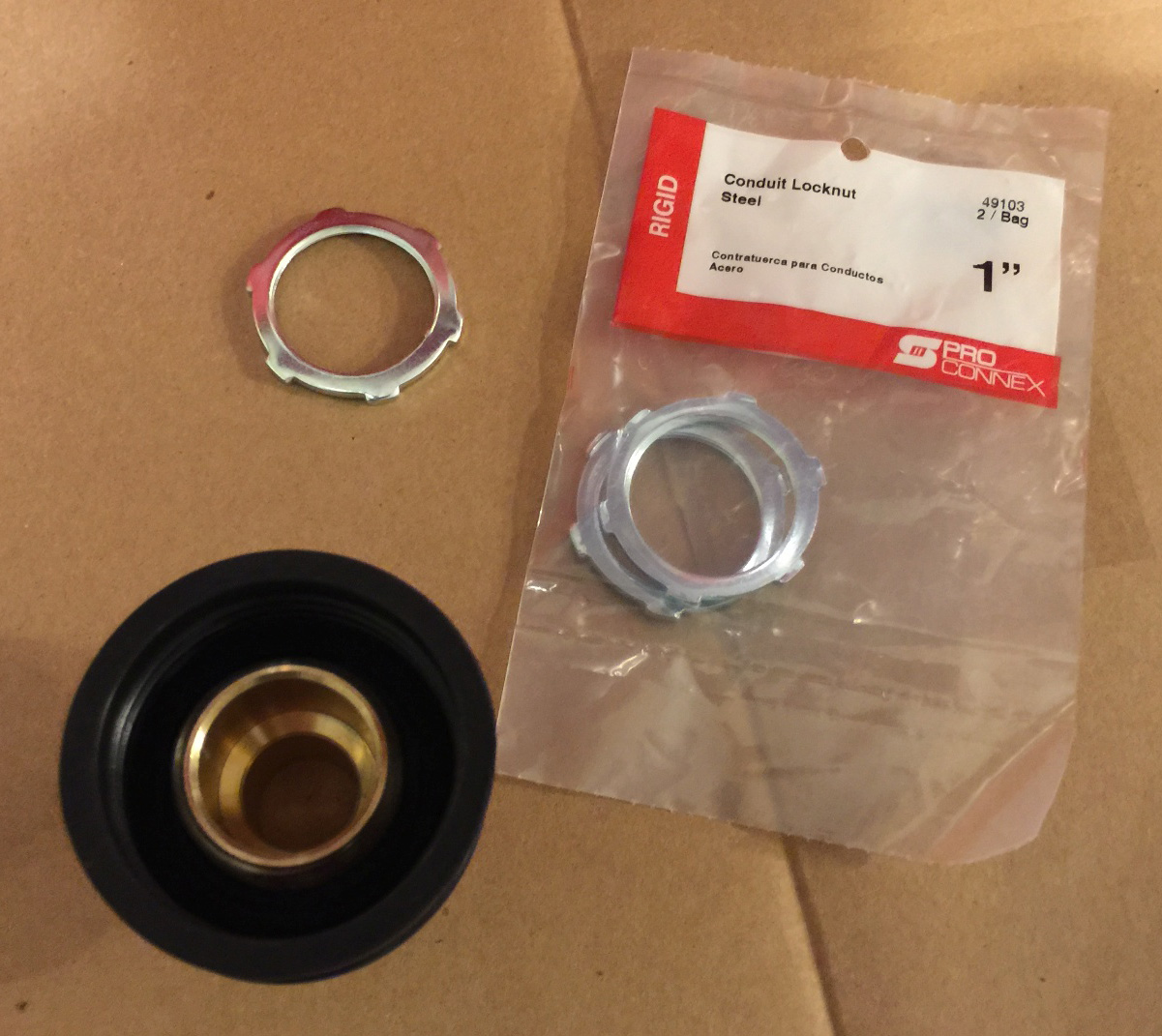
Thread the conduit locknut onto the male adapter, and spin the locknut down to the rubber surface. Once you meet resistance, you can turn the adapter, itself, while holding the locknut inside the rubber with a finger - it will grip the surface while tightening.
Finished product:
Next up, we need to cut a small length of 1.5" silicone pipe. By sliding the pipe into the rubber cap, you can draw the cut circle on the outside of the pipe. Use a large pipe cutter or blade to make your silicone cut. You will end up with something like this:
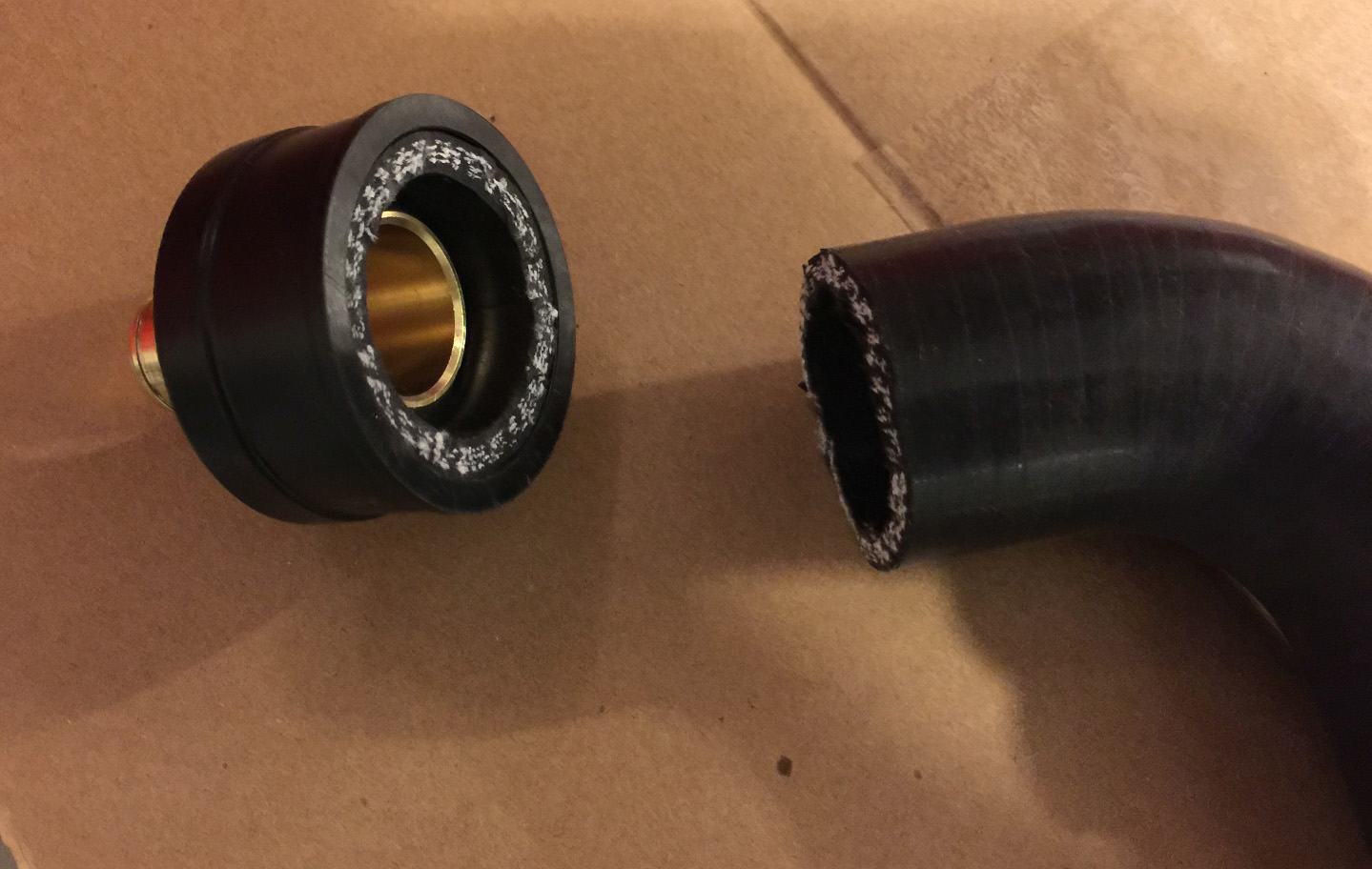
You can see where we're going with this (it becomes a slip fitting/buffer):
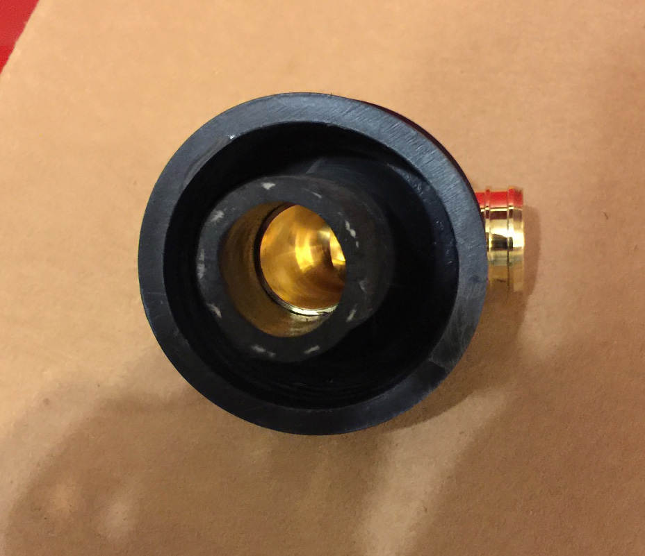
The second cap and adapter now need to be fitted. Drill a 3/4" hole in the middle of the second rubber pipe cap. Once this hole is drilled, slide the 1" adapter in - this will be an extremely tight fit. If you need to bore out a bit more material (as I did), you can use a Dremel grinder. Be careful! It is very important that this connection be very tight, as the retention is essentially relying on the adapter to sit extremely snugly in place.
To hold the adapter in-place, use a small section of 3/4" hose. You may need to heat the hose, as with all of these connections - after all, we're using a smaller hose size than normal to avoid additional clamps, etc. If you have drilled this correctly, the hose will hold the adapter firmly in place - trust me, it's not going anywhere.
Next up, do the exact same thing with regard to the silicone pipe above. I won't clutter this with another picture - simply insert and cut the 1.5" pipe just as before.
Now that you have the two small 1.5" sections, you may want to get rid of the white poly string look on the side of the silicone facing the breather. To do this, just grab a black paint pen (works much better than a Sharpie) and go over the thread until it's all completely black.
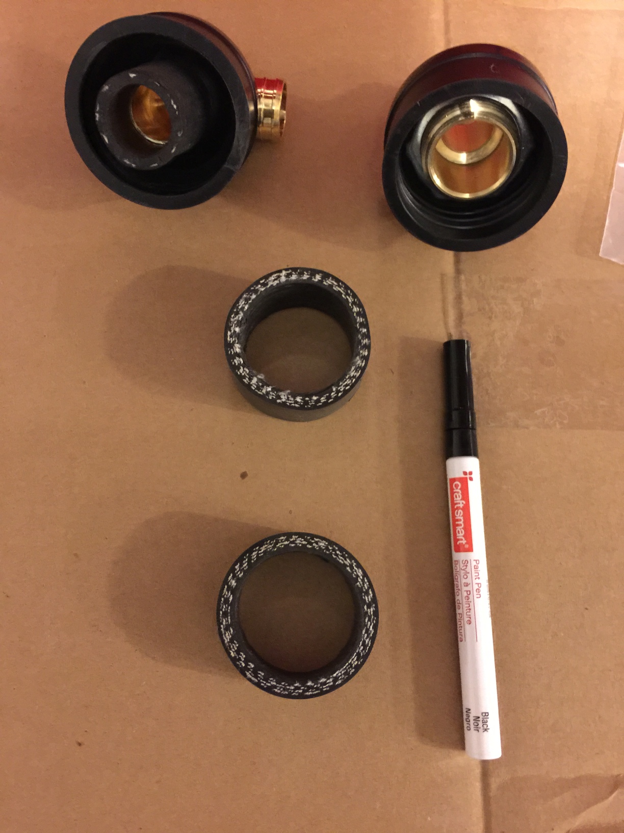
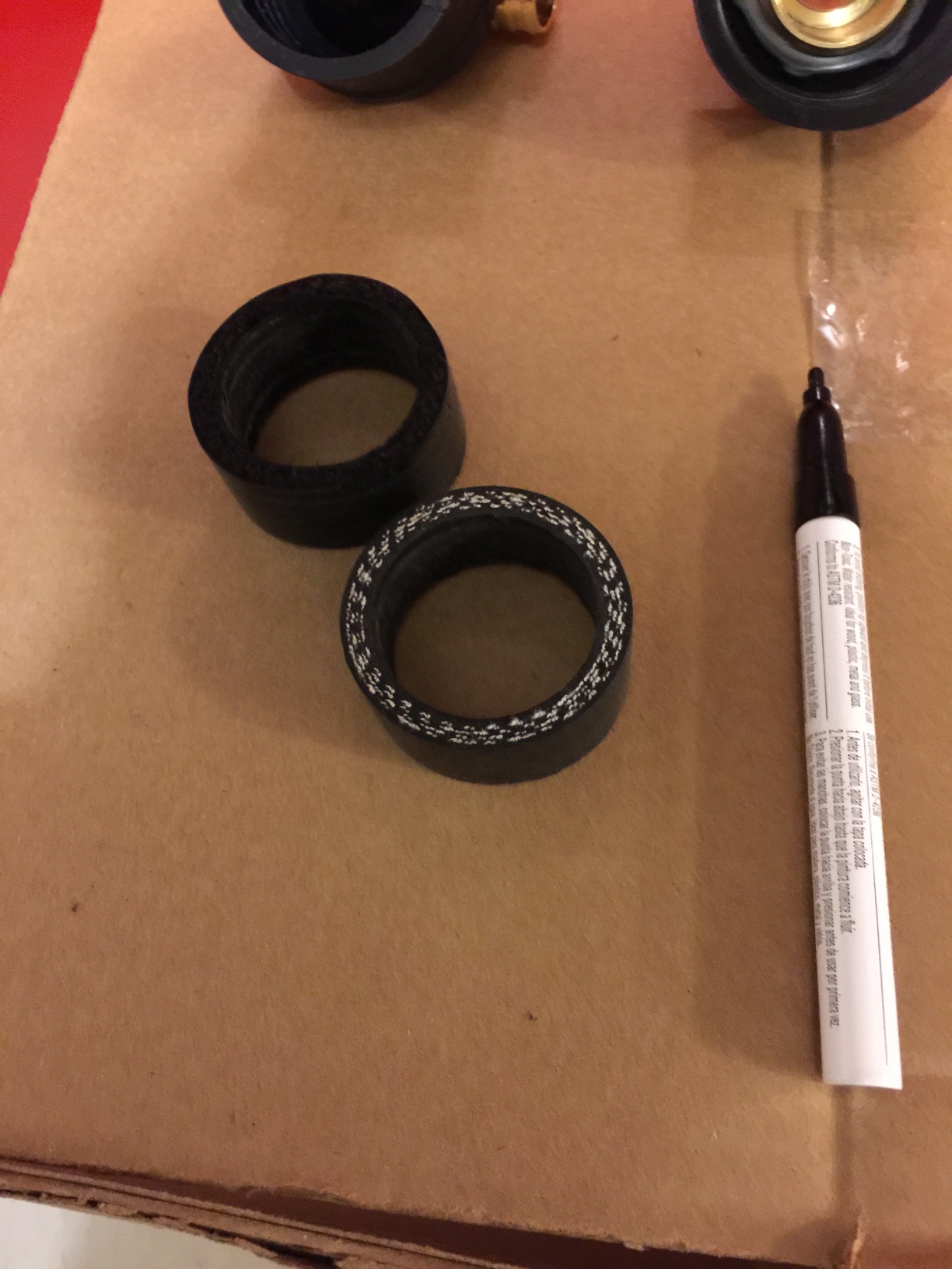
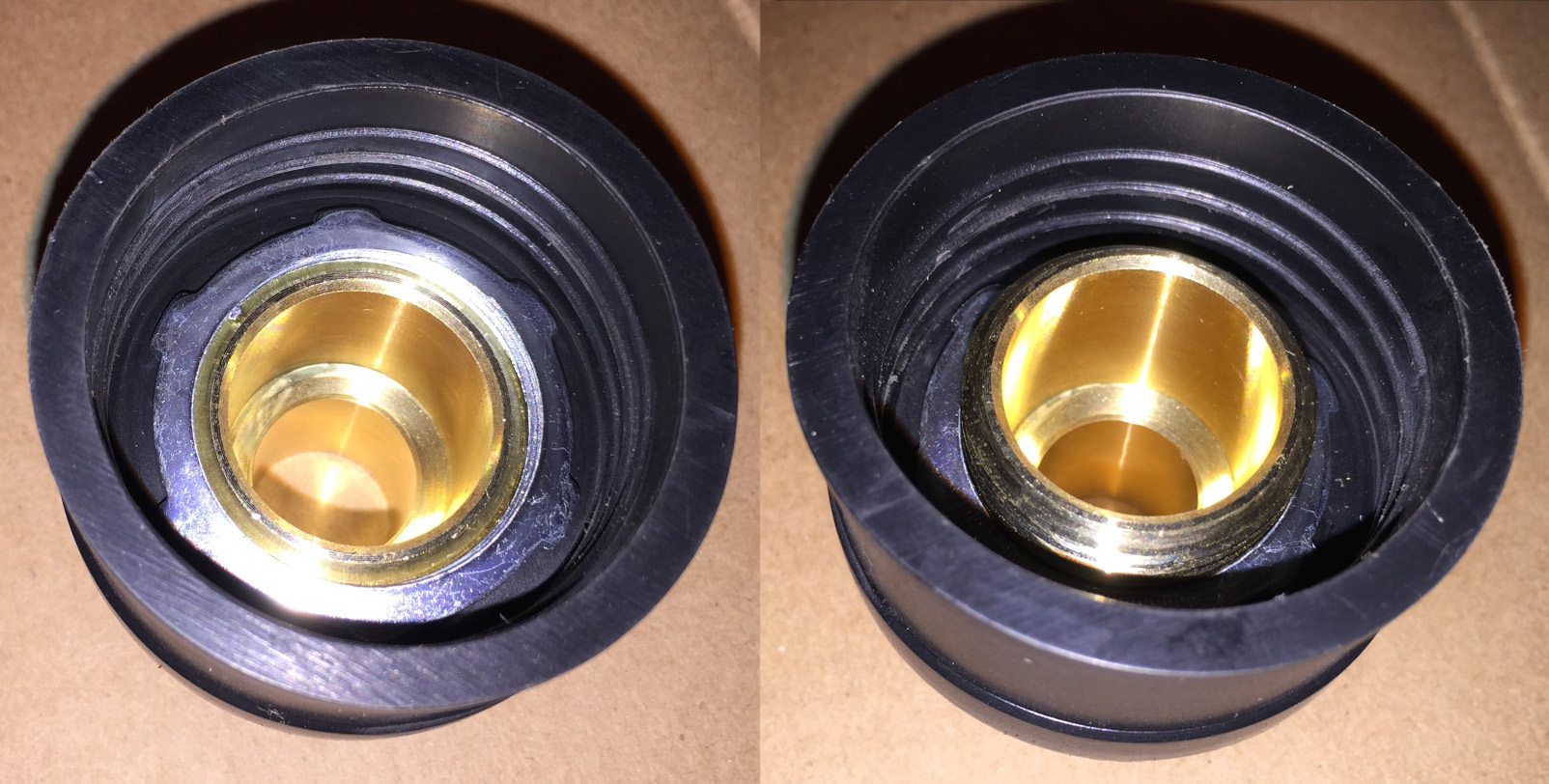
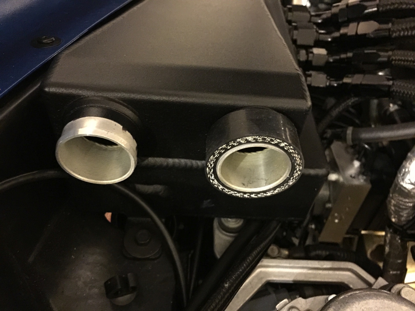
Once you have those to your liking, slide the hose sections back into the rubber caps. Note that each cap may have a slightly different sized silicone remnant due to depth impacted by the locknut. You can see the difference in size here:
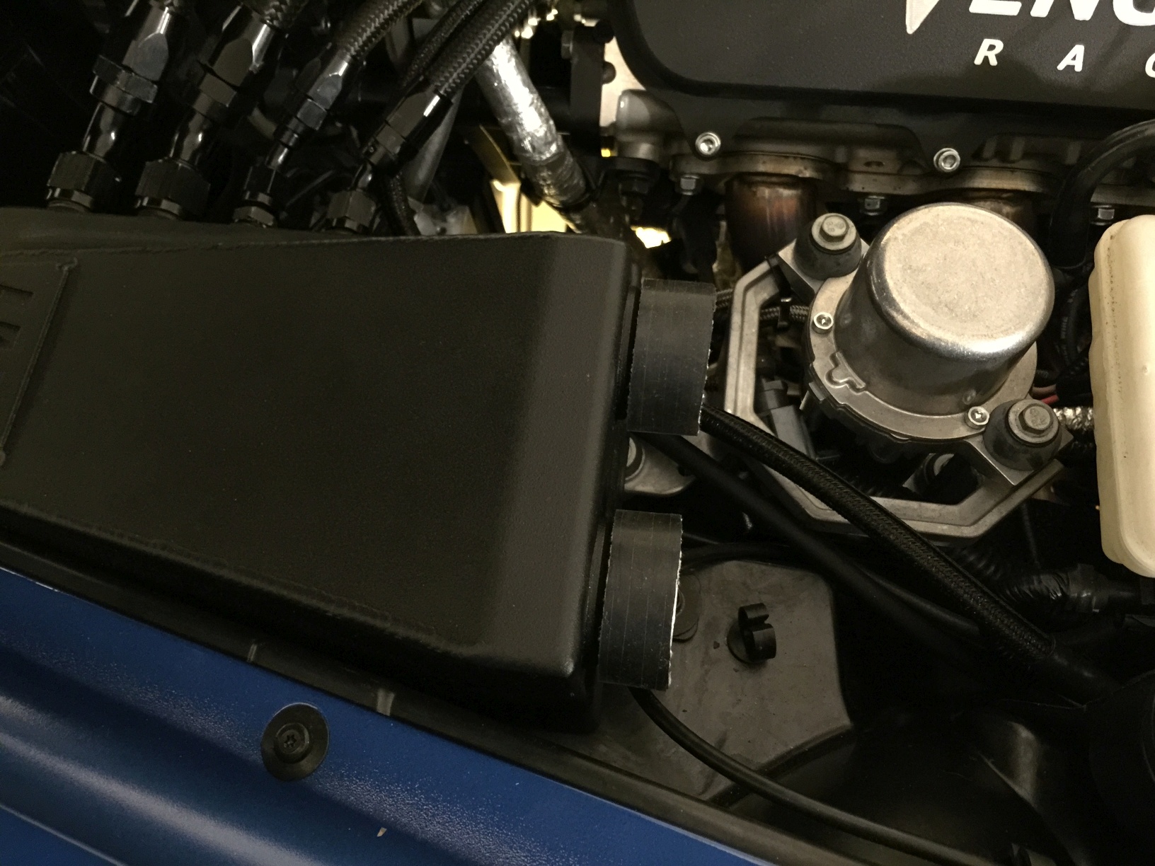
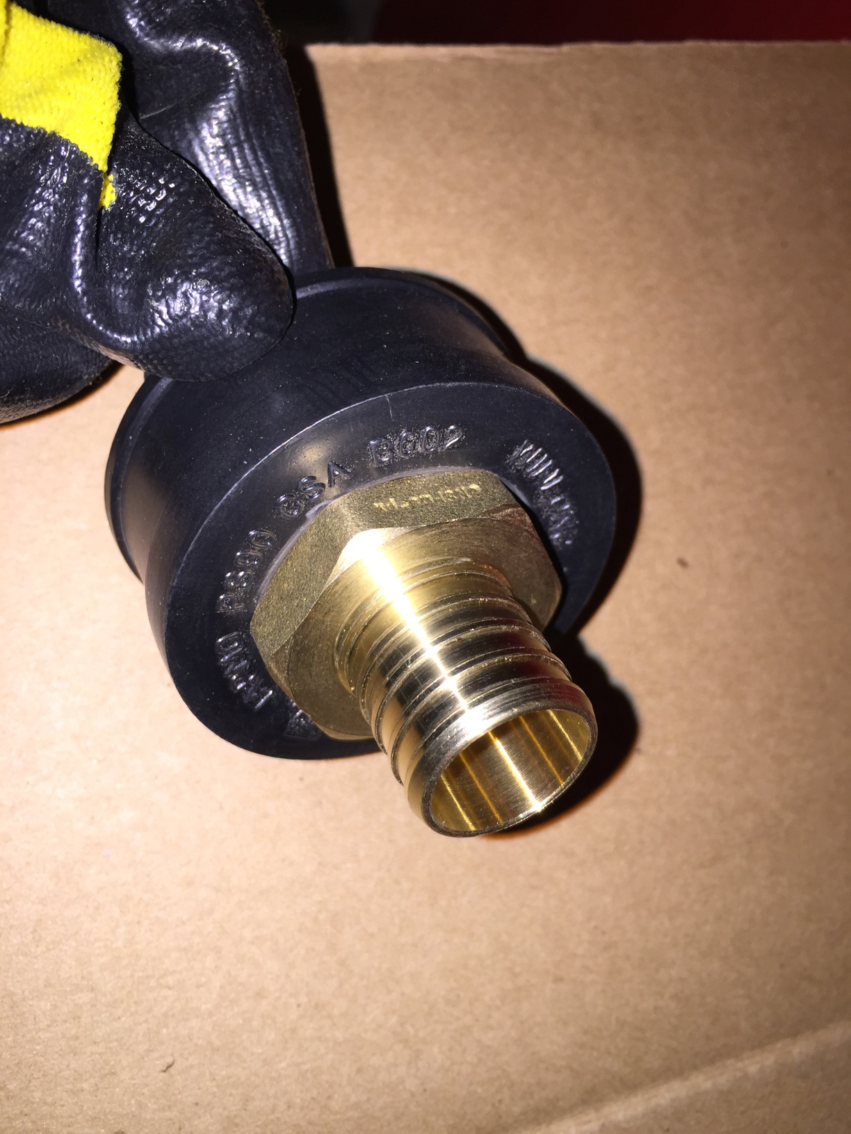
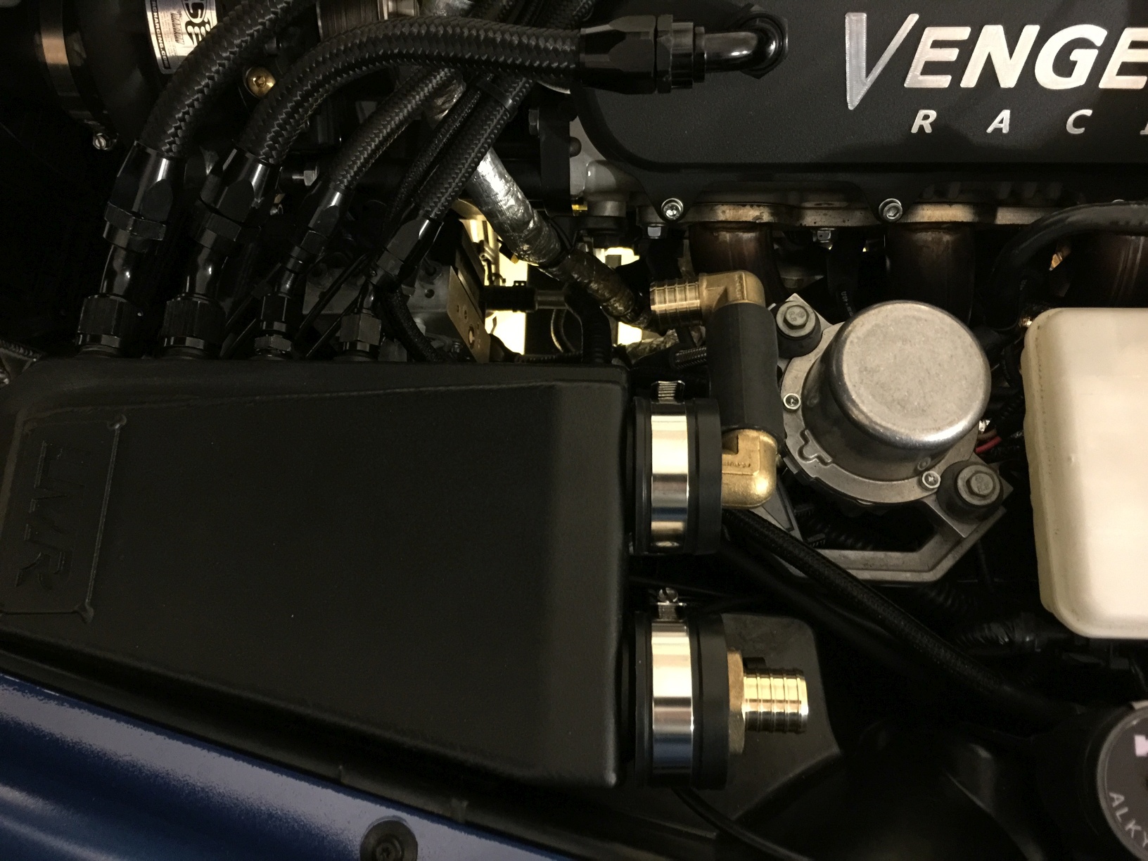
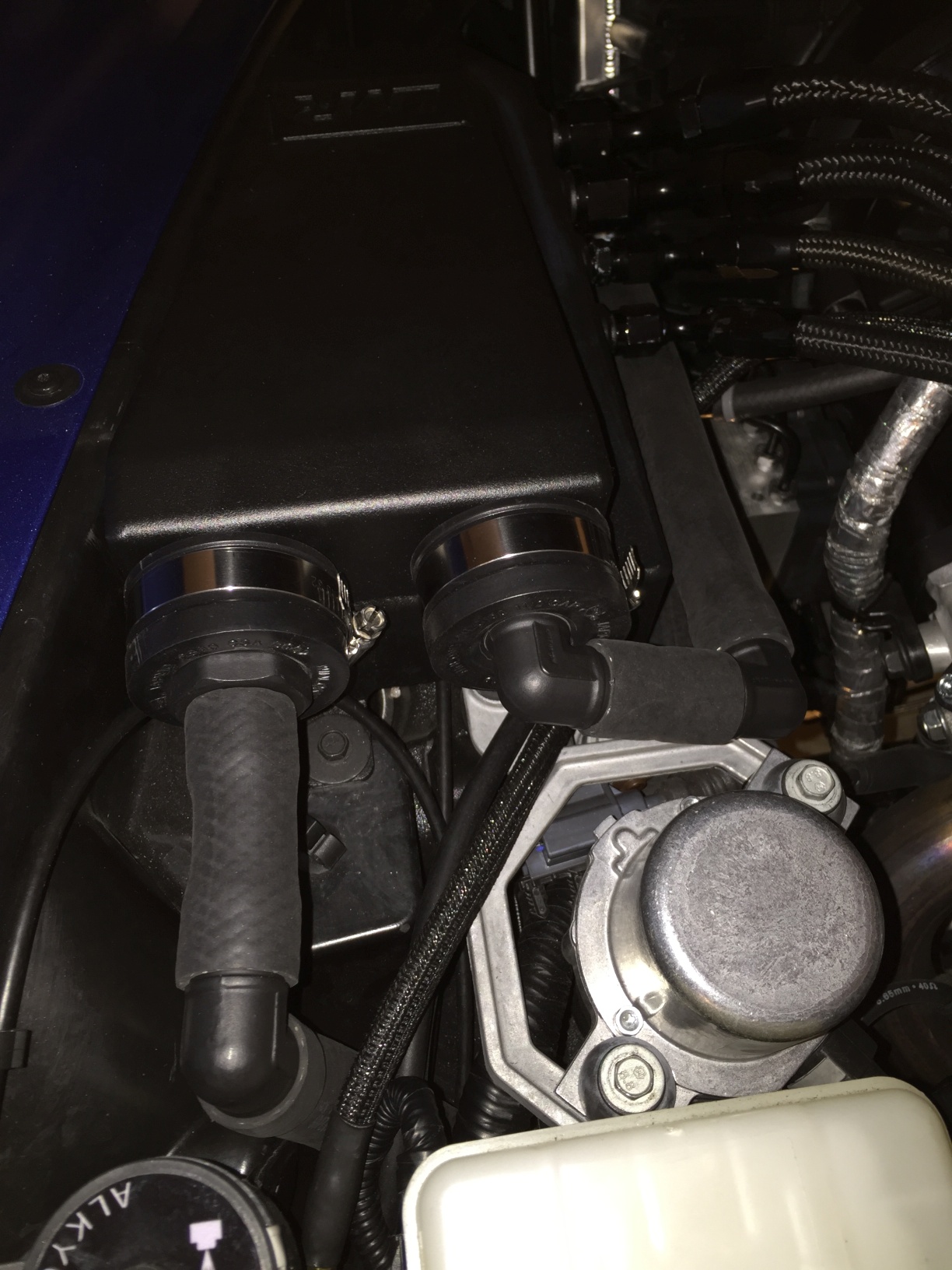
Now, slide the entire assemblies onto the hose ends of the breather. Tighten the clamps to a reasonable level (I use a 5/6 on my DeWalt driver) Essentially, you're at this point now:
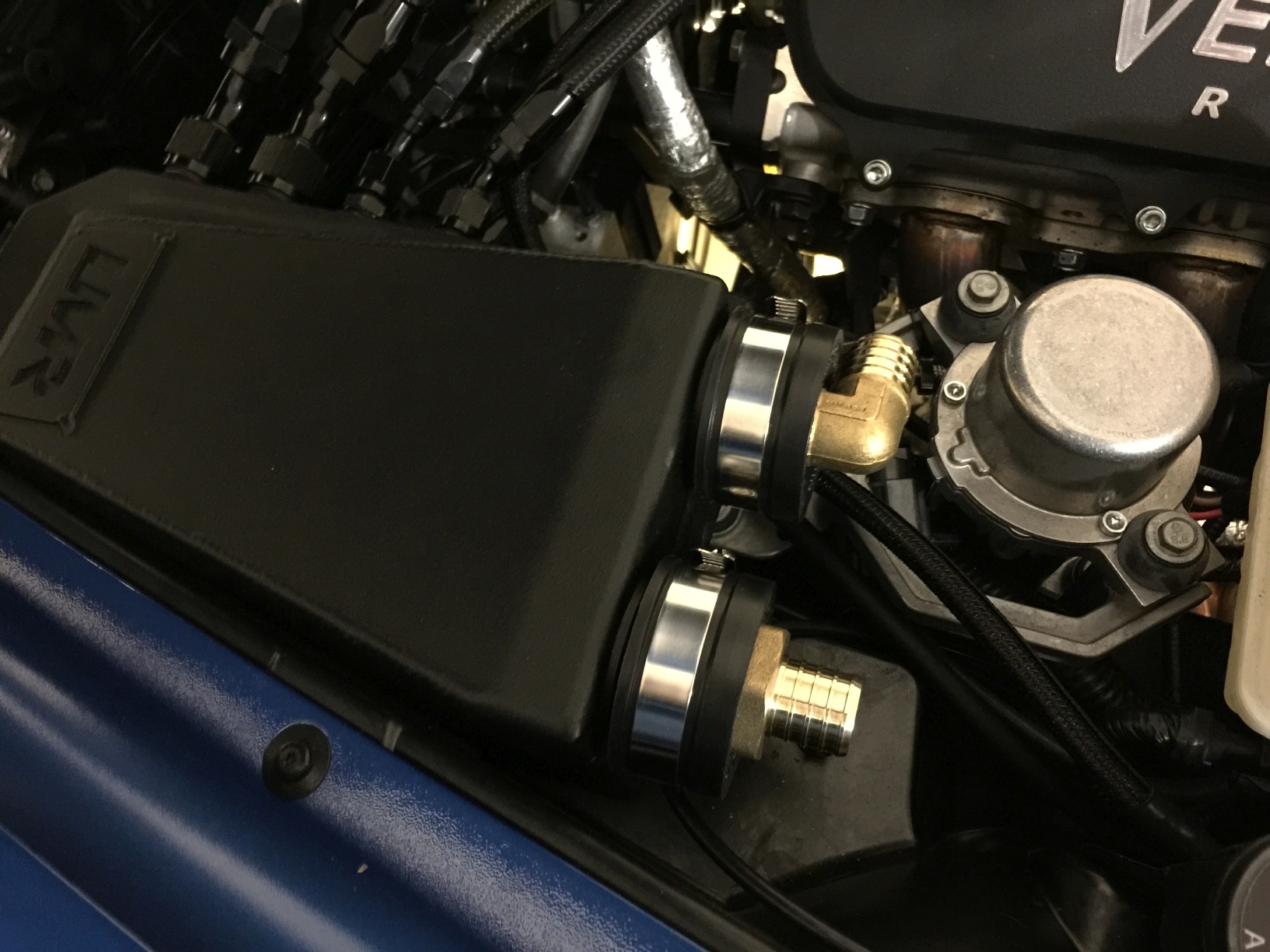
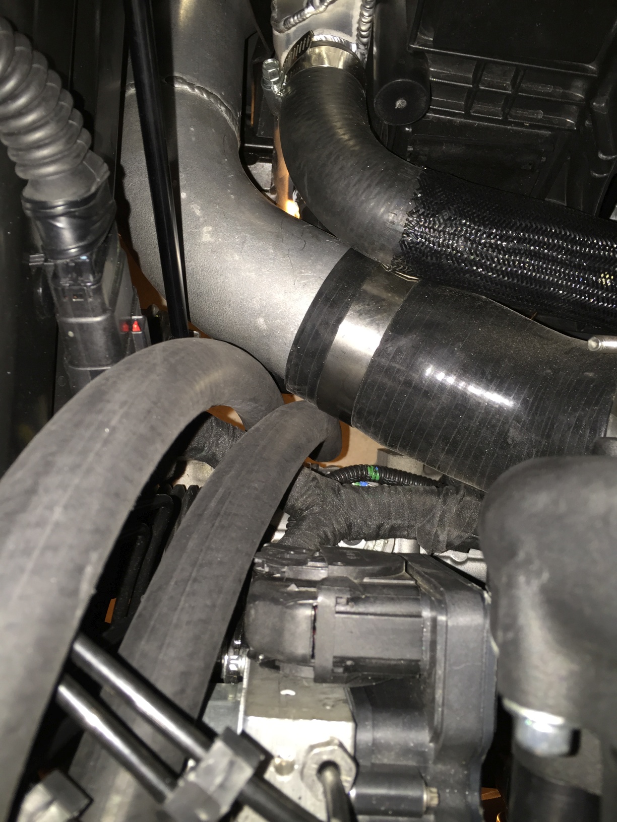
As you've already used a small amount of this 3/4" ArmorMark hose to secure the 90-degree fitting, you'll notice the size. Here's an image just to show scale - it's rather large. Now, some of you may say, "Why did you use 3/4" instead of 1" hose?" - the answer is a three-parter. First, the 3/4" hose is available on the shelf, while the 1" is usually a special order, and more than double the price. Second, the outside diameter of 1" hose makes it prohibitive to use in the small space we have, and third (and most importantly to me), the 3/4" forms a tight seal over the adapters eliminating the need for any clamps, thereby limiting the points of failure in the setup. The downside of this approach, however, is that you need to heat each hose end with a stout hairdryer on high, or heat gun on low. Then, once hot, you can press the hose onto the 1" fittings with relative ease.
As you can already see in that photo, we're going to make our first turn using a short length of hose, and a second adapter. Cut a 2-3" piece of hose and join the adapters as shown. You will need to heat both ends of the hose for this. Remember to wear gloves, as this will get hot on shorter pieces like this.
Start by removing the 1" by 1" male adapter from the package, as shown. Taking one of the 1.5" flexible pipe caps, and using either a drill press or drill, cut/drill a 1-1/4" hole in the center of the pipe cap. Refine the edge until the 1" x 1" adapter threads into the hole. Make sure it's still snug, as we're going to be using the material surrounding the adapter to clamp the pieces together using a steel conduit locknut, shown below.
Thread the conduit locknut onto the male adapter, and spin the locknut down to the rubber surface. Once you meet resistance, you can turn the adapter, itself, while holding the locknut inside the rubber with a finger - it will grip the surface while tightening.
Finished product:
Next up, we need to cut a small length of 1.5" silicone pipe. By sliding the pipe into the rubber cap, you can draw the cut circle on the outside of the pipe. Use a large pipe cutter or blade to make your silicone cut. You will end up with something like this:
You can see where we're going with this (it becomes a slip fitting/buffer):
The second cap and adapter now need to be fitted. Drill a 3/4" hole in the middle of the second rubber pipe cap. Once this hole is drilled, slide the 1" adapter in - this will be an extremely tight fit. If you need to bore out a bit more material (as I did), you can use a Dremel grinder. Be careful! It is very important that this connection be very tight, as the retention is essentially relying on the adapter to sit extremely snugly in place.
To hold the adapter in-place, use a small section of 3/4" hose. You may need to heat the hose, as with all of these connections - after all, we're using a smaller hose size than normal to avoid additional clamps, etc. If you have drilled this correctly, the hose will hold the adapter firmly in place - trust me, it's not going anywhere.
Next up, do the exact same thing with regard to the silicone pipe above. I won't clutter this with another picture - simply insert and cut the 1.5" pipe just as before.
Now that you have the two small 1.5" sections, you may want to get rid of the white poly string look on the side of the silicone facing the breather. To do this, just grab a black paint pen (works much better than a Sharpie) and go over the thread until it's all completely black.
Once you have those to your liking, slide the hose sections back into the rubber caps. Note that each cap may have a slightly different sized silicone remnant due to depth impacted by the locknut. You can see the difference in size here:
Now, slide the entire assemblies onto the hose ends of the breather. Tighten the clamps to a reasonable level (I use a 5/6 on my DeWalt driver) Essentially, you're at this point now:
As you've already used a small amount of this 3/4" ArmorMark hose to secure the 90-degree fitting, you'll notice the size. Here's an image just to show scale - it's rather large. Now, some of you may say, "Why did you use 3/4" instead of 1" hose?" - the answer is a three-parter. First, the 3/4" hose is available on the shelf, while the 1" is usually a special order, and more than double the price. Second, the outside diameter of 1" hose makes it prohibitive to use in the small space we have, and third (and most importantly to me), the 3/4" forms a tight seal over the adapters eliminating the need for any clamps, thereby limiting the points of failure in the setup. The downside of this approach, however, is that you need to heat each hose end with a stout hairdryer on high, or heat gun on low. Then, once hot, you can press the hose onto the 1" fittings with relative ease.
As you can already see in that photo, we're going to make our first turn using a short length of hose, and a second adapter. Cut a 2-3" piece of hose and join the adapters as shown. You will need to heat both ends of the hose for this. Remember to wear gloves, as this will get hot on shorter pieces like this.
Last edited by Theta; 03-28-2015 at 11:51 PM. Reason: Adding content
03-28-2015, 09:00 PM
#4
Tech Contributor
Thread Starter
Member Since: Jan 2006
Location: Saint Louis MO
Posts: 4,761
Likes: 0
Received 219 Likes
on
110 Posts
St. Jude Donor '14-'15
Before we continue, I wanted to add a section on paint. I decided that the brass look wasn't for me - after all, I think there's enough brass floating around from the meth nozzles, etc.
Using a fresh can of Rustoleum Professional Flat Black spray paint, I applied three coats. The first one was fairly light, as the brass doesn't cover well with a single coat. Feel free to use gloss black, or a clearcoat to protect the finish. Or, for those looking for more color - you can use just about anything you'd like. Or, you can leave it alone and save the time!
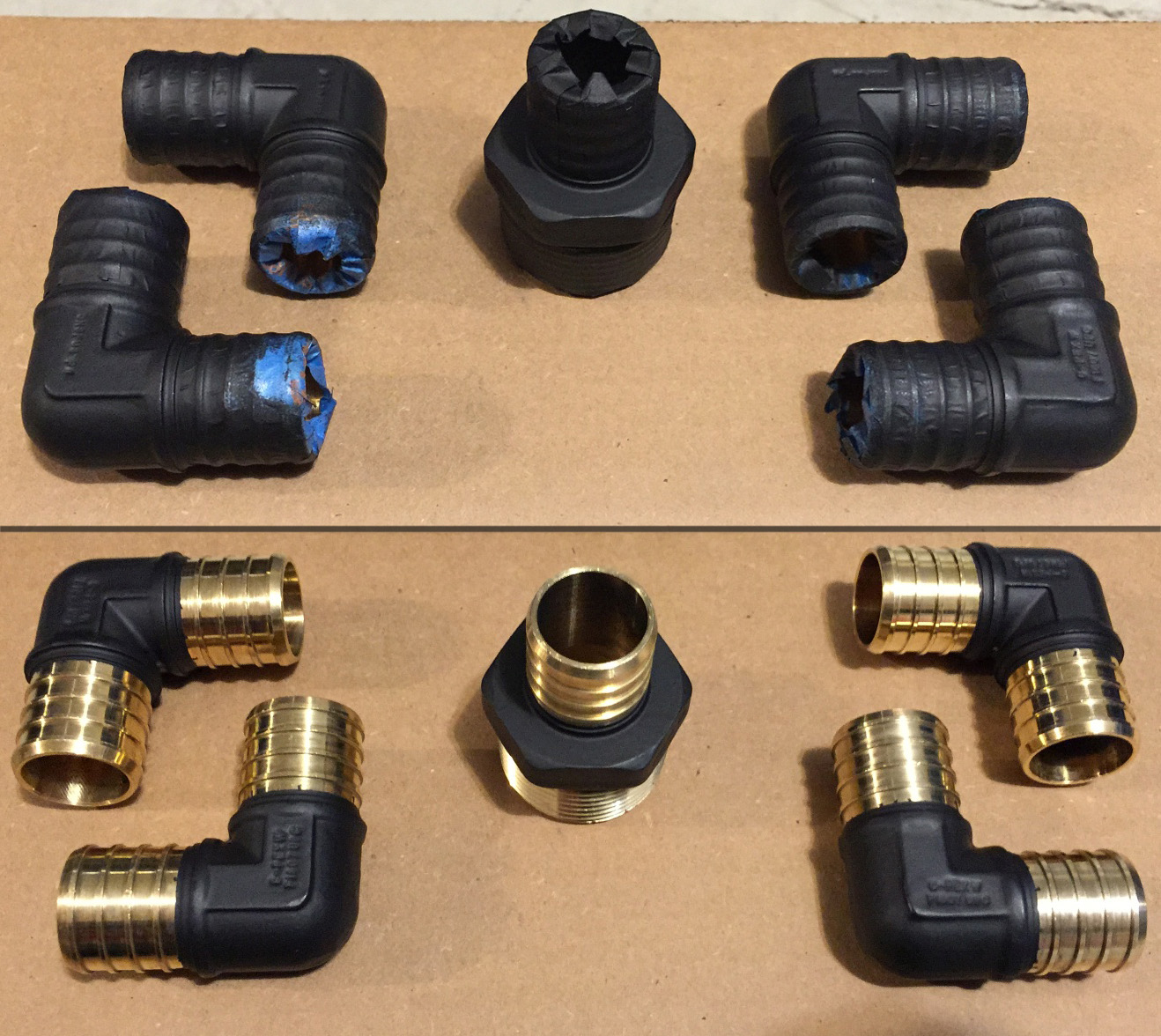
Now you'll see why all the photos from here on out have black fittings.
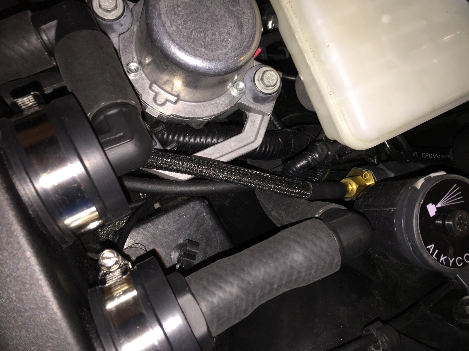
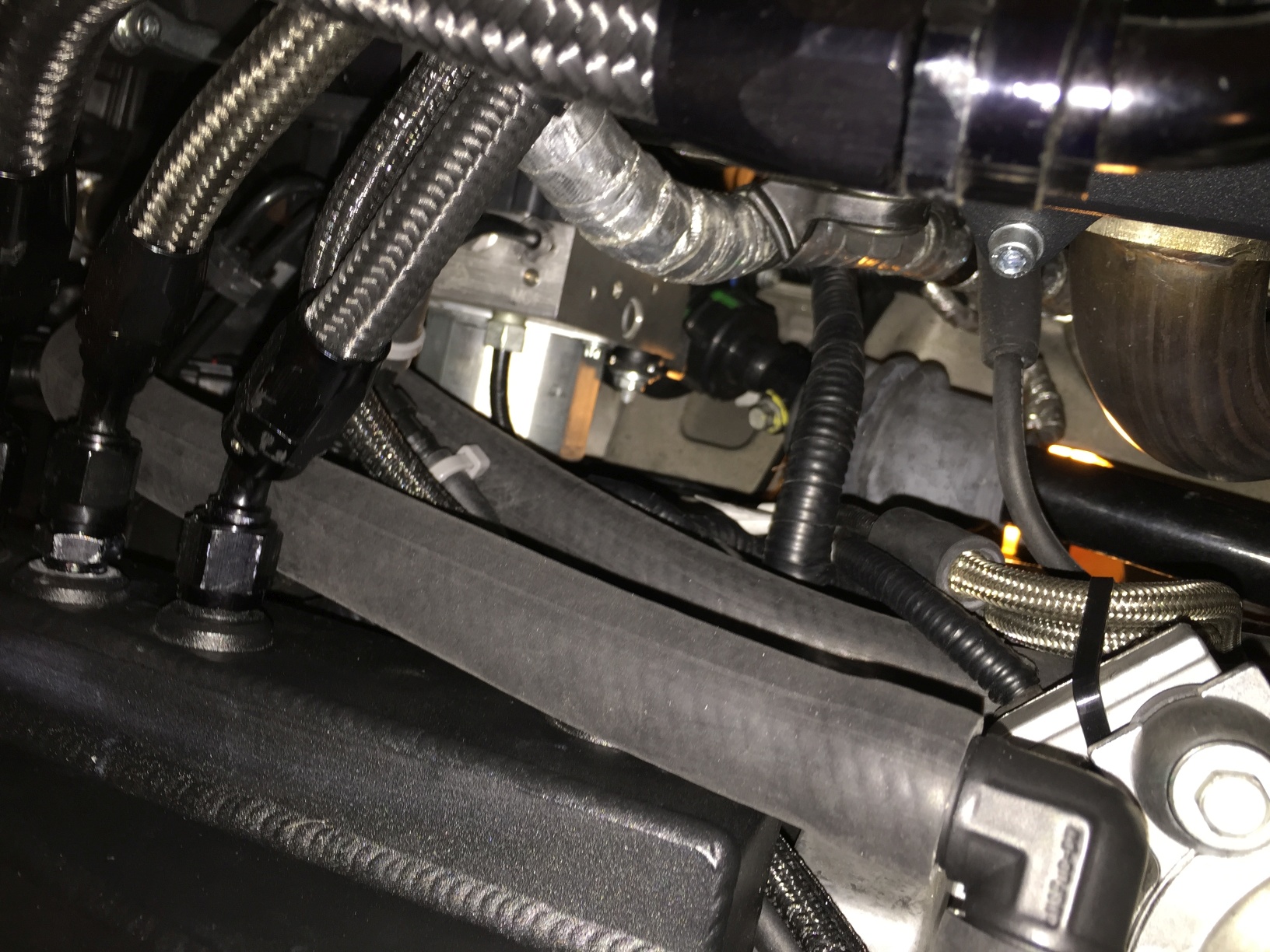
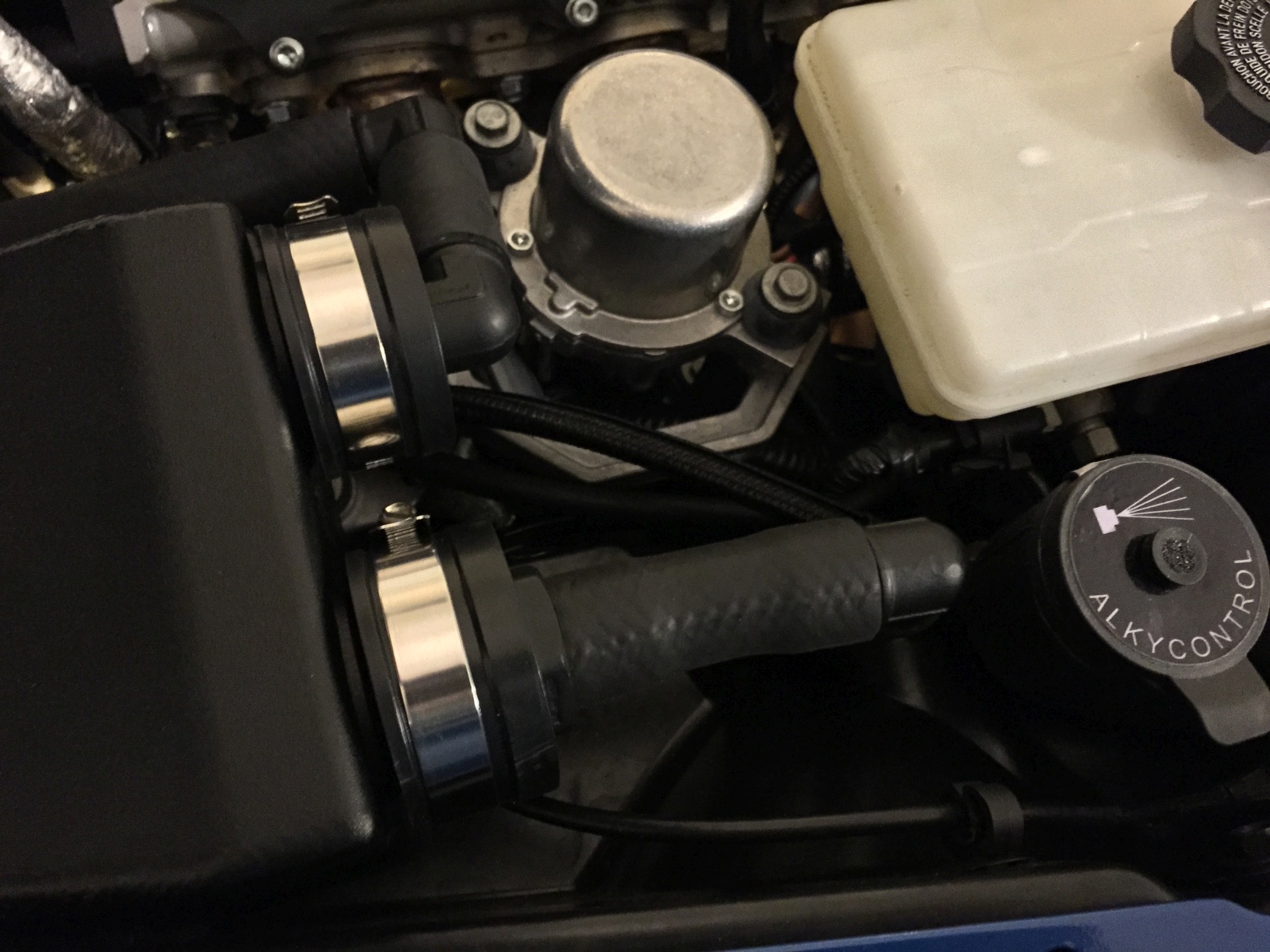
Moving to the next outlet (with the straight fitting), cut a 3" to 3-1/2" piece of hose, and join the outlet with an adapter pointing down and slightly to the side. With these fittings, you'll find that once the hose has joined, rotating isn't all that hard.
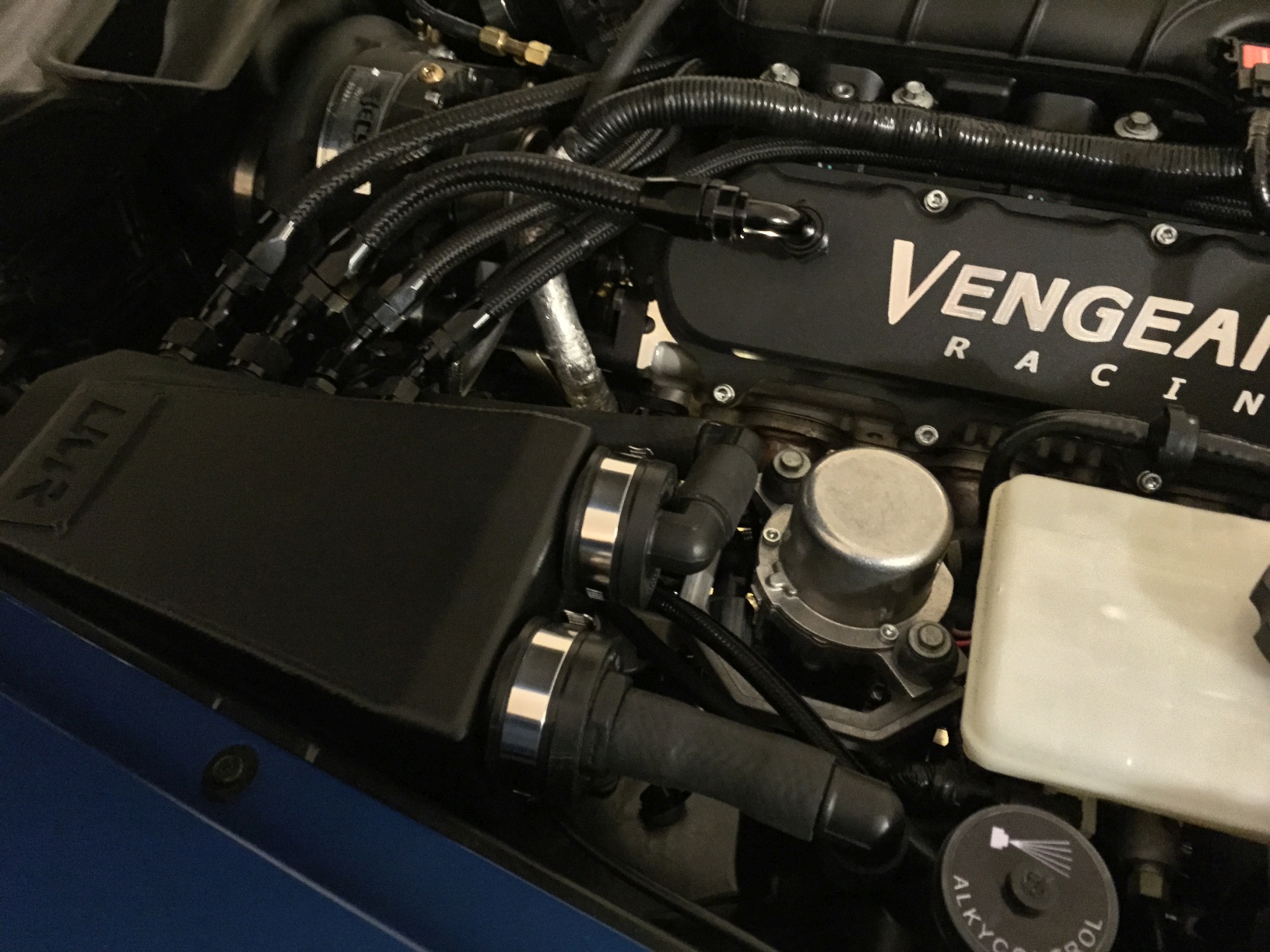
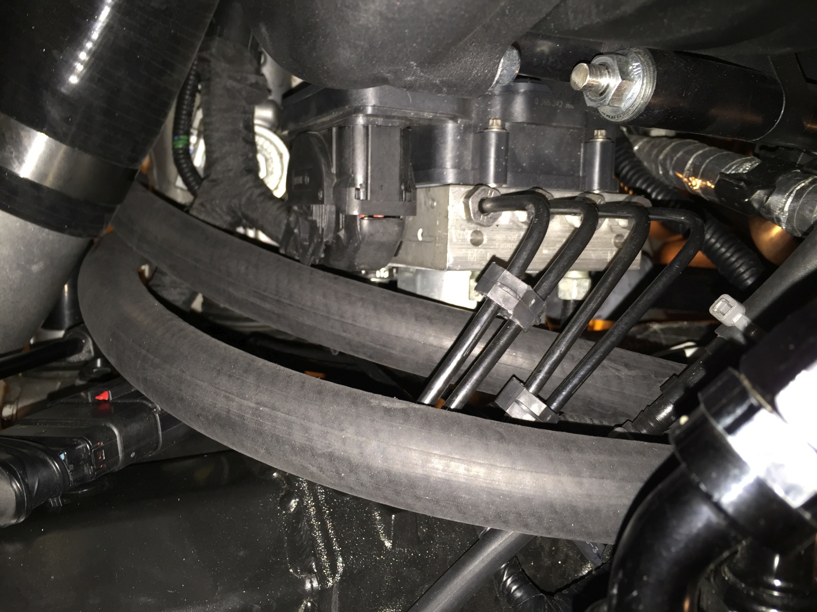
Cut a 1-foot section of hose, and run it as shown in the next picture. You're going to be routing under the wiring, and coming out near the headers. You will need to trim this piece to size once you have estimated the proper length.
Take that section of hose, and add an adapter to one side while it is outside the car - it's easier to do this before it's in there. Now that you've added this adapter, you can route it as before, and heat/join the other end with the angle coming off of the main barb (right by the washer tank as shown).
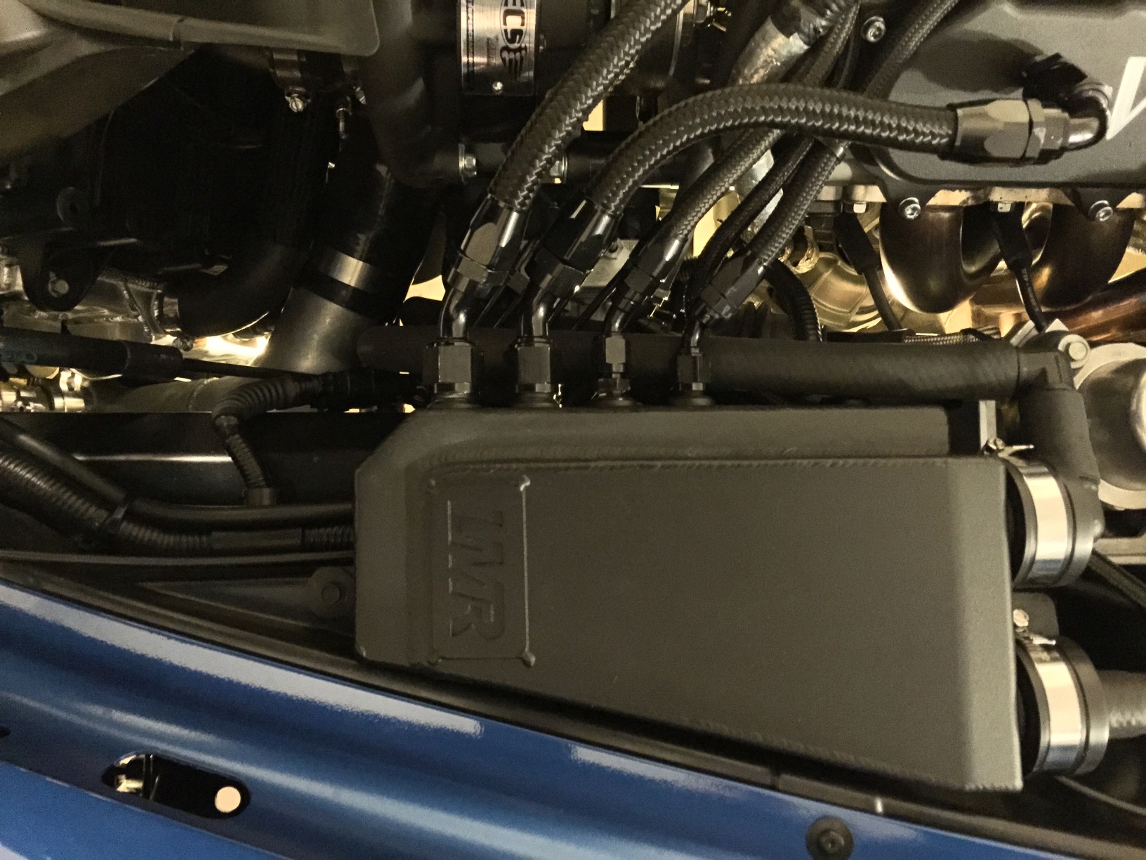
Once you've done this, you can join both remaining adapter barbs (now pointing toward the nose of the car) with the final sections of hose. Heat/join the adapter closest to the headers with a 3 to 3-1/2 foot length of hose.
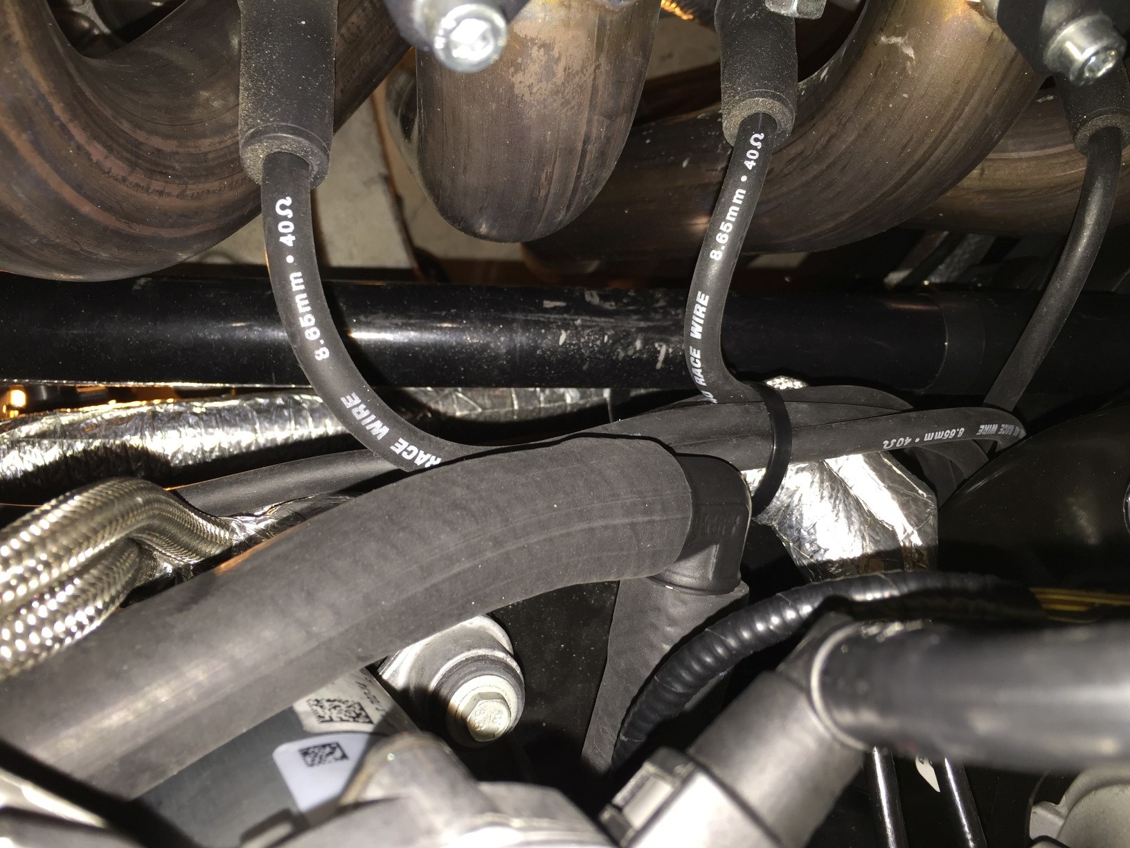
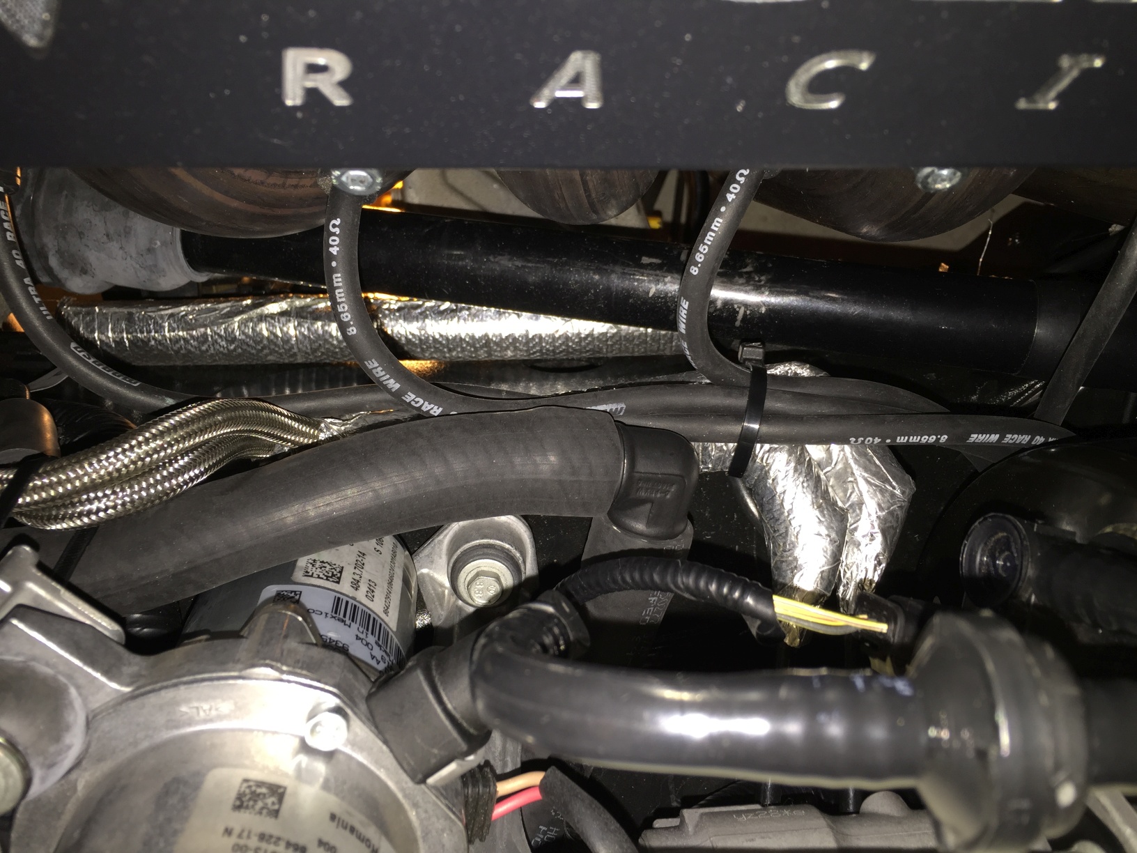
Do the same with the other adapter near the breather, only using a shorter section of hose. 2-1/2 to 3 feet will more than suffice. Route both hoses as shown (or to your liking):
Using a fresh can of Rustoleum Professional Flat Black spray paint, I applied three coats. The first one was fairly light, as the brass doesn't cover well with a single coat. Feel free to use gloss black, or a clearcoat to protect the finish. Or, for those looking for more color - you can use just about anything you'd like. Or, you can leave it alone and save the time!
Now you'll see why all the photos from here on out have black fittings.
Moving to the next outlet (with the straight fitting), cut a 3" to 3-1/2" piece of hose, and join the outlet with an adapter pointing down and slightly to the side. With these fittings, you'll find that once the hose has joined, rotating isn't all that hard.
Cut a 1-foot section of hose, and run it as shown in the next picture. You're going to be routing under the wiring, and coming out near the headers. You will need to trim this piece to size once you have estimated the proper length.
Take that section of hose, and add an adapter to one side while it is outside the car - it's easier to do this before it's in there. Now that you've added this adapter, you can route it as before, and heat/join the other end with the angle coming off of the main barb (right by the washer tank as shown).
Once you've done this, you can join both remaining adapter barbs (now pointing toward the nose of the car) with the final sections of hose. Heat/join the adapter closest to the headers with a 3 to 3-1/2 foot length of hose.
Do the same with the other adapter near the breather, only using a shorter section of hose. 2-1/2 to 3 feet will more than suffice. Route both hoses as shown (or to your liking):
Last edited by Theta; 03-28-2015 at 11:14 PM. Reason: Adding content
03-28-2015, 11:13 PM
#5
Tech Contributor
Thread Starter
Member Since: Jan 2006
Location: Saint Louis MO
Posts: 4,761
Likes: 0
Received 219 Likes
on
110 Posts
St. Jude Donor '14-'15
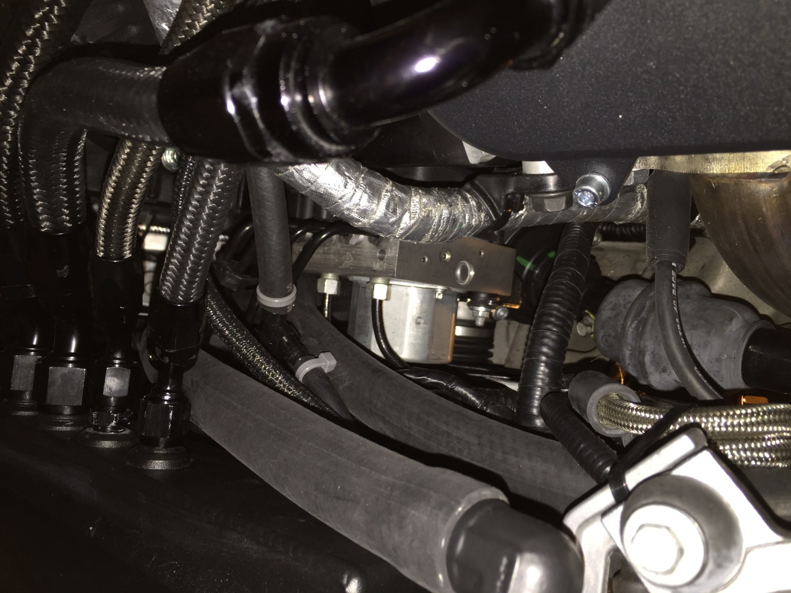
The finished product will look like this, or something similar:
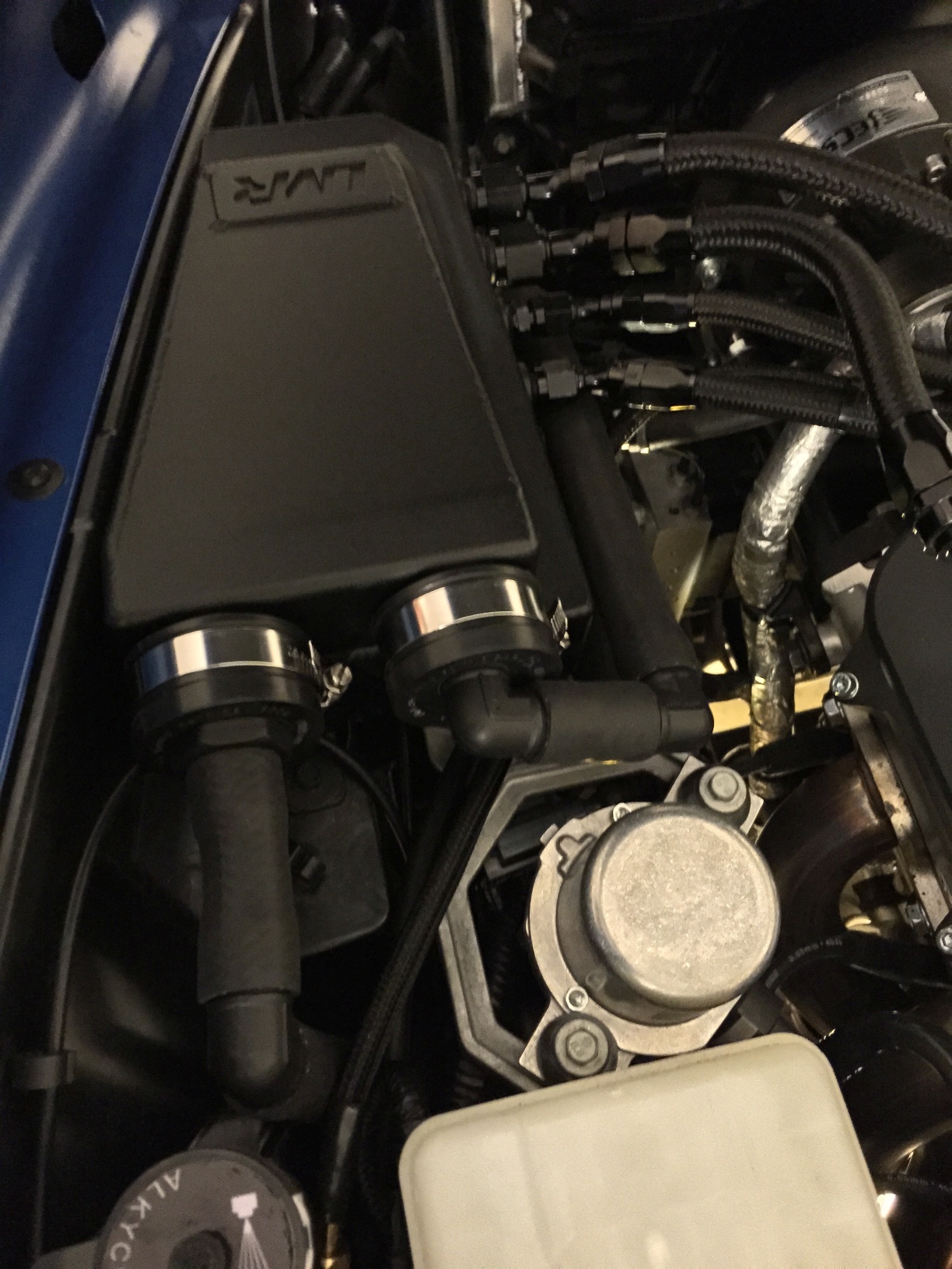
Attachment 48368438
Please let me know if this helped you, or if you have questions or suggestions.
.
Attachment 48368438
Please let me know if this helped you, or if you have questions or suggestions.
.
Last edited by Theta; 03-30-2015 at 04:03 AM.
03-28-2015, 11:20 PM
#6
Tech Contributor
Thread Starter
Member Since: Jan 2006
Location: Saint Louis MO
Posts: 4,761
Likes: 0
Received 219 Likes
on
110 Posts
St. Jude Donor '14-'15
Another option that occurred to me during this process would be to cap the lower outlet on the breather with a non-drilled end cap, and just run the above setup with the top two 90-degree adapters.
You can then run a single hose to the bottom, or to the hood scoop. It's easier, but will give you half the flow of this setup.
The required parts would narrow down to the two caps, two angle adapters, 4 feet of hose, and the 1.5" silicone hose.
You can then run a single hose to the bottom, or to the hood scoop. It's easier, but will give you half the flow of this setup.
The required parts would narrow down to the two caps, two angle adapters, 4 feet of hose, and the 1.5" silicone hose.
03-29-2015, 12:30 AM
#7
Instructor


Another option that occurred to me during this process would be to cap the lower outlet on the breather with a non-drilled end cap, and just run the above setup with the top two 90-degree adapters.
You can then run a single hose to the bottom, or to the hood scoop. It's easier, but will give you half the flow of this setup.
The required parts would narrow down to the two caps, two angle adapters, 4 feet of hose, and the 1.5" silicone hose.
You can then run a single hose to the bottom, or to the hood scoop. It's easier, but will give you half the flow of this setup.
The required parts would narrow down to the two caps, two angle adapters, 4 feet of hose, and the 1.5" silicone hose.
That said, It looks to be a nice kit but I may actually "relocate" the relocate hoses to beneath the car as you did. I was hoping to see some solid answers from the "Breather modification thread LMR started but didn't elaborate on. So this has me concerned. Anyway , getting off subject ( sort of). Thanks again for your thorough description of the work you did. It looks nice and I am sure it will perform better at keeping the fumes out than my $400 relocation to the hood scoop. CHEERS!
 03-29-2015, 12:46 AM
#9
Instructor

You have come a long way with the finished product. NOW package it and sell it! It's your work and completly unique. If I had to pick between yours and the mystery LMR relocation kit for $400 I would have picked yours because of the commonsense approach of getting the fumes AWAY from the engine bay. NO offense to LMR, kit seems solid and I know some really good welder put a lot of time and precision into building this unit for LMR , but they really need to provide better support if they are going to post on the Corvette forum and use it to sell their products. Good Stuff Theta.
03-29-2015, 12:52 AM
#10
Tech Contributor
Thread Starter
Member Since: Jan 2006
Location: Saint Louis MO
Posts: 4,761
Likes: 0
Received 219 Likes
on
110 Posts
St. Jude Donor '14-'15
Anything with PVC looks like absolute crap. Works, but looks like crap.
Had to get the angles down to make the CNC draft, but then couldn't source any close-radius silicone hose for reasonable money. That one stupid little CNC part cost $40 to make, and wouldn't have given enough flow anyway.
Thanks for the kind words. I think their relocation kit is great for those who haven't powdercoated, and for new buyers. For those of us that already PC'ed, or just want a non-welded setup, I thought this might help.
I do know the LMR kit has a lot of expensive parts - those -16AN fittings are between $50 and $80 a pop, plus another $60 for the braided 350 hose.
I debated going expensive this time, but decided it was better to do it this way. No reason to make people spend a bunch of money on DIY. If I change the hoses over to 350 16AN braided, then add the clamps, etc... We're getting into the other end of the spectrum.
Thanks again for the kind words - makes the time spent worthwhile.
03-29-2015, 10:13 PM
#11
Anything with PVC looks like absolute crap. Works, but looks like crap.
Had to get the angles down to make the CNC draft, but then couldn't source any close-radius silicone hose for reasonable money. That one stupid little CNC part cost $40 to make, and wouldn't have given enough flow anyway.
Thanks for the kind words. I think their relocation kit is great for those who haven't powdercoated, and for new buyers. For those of us that already PC'ed, or just want a non-welded setup, I thought this might help.
I do know the LMR kit has a lot of expensive parts - those -16AN fittings are between $50 and $80 a pop, plus another $60 for the braided 350 hose.
I debated going expensive this time, but decided it was better to do it this way. No reason to make people spend a bunch of money on DIY. If I change the hoses over to 350 16AN braided, then add the clamps, etc... We're getting into the other end of the spectrum.
Thanks again for the kind words - makes the time spent worthwhile.
Had to get the angles down to make the CNC draft, but then couldn't source any close-radius silicone hose for reasonable money. That one stupid little CNC part cost $40 to make, and wouldn't have given enough flow anyway.
Thanks for the kind words. I think their relocation kit is great for those who haven't powdercoated, and for new buyers. For those of us that already PC'ed, or just want a non-welded setup, I thought this might help.
I do know the LMR kit has a lot of expensive parts - those -16AN fittings are between $50 and $80 a pop, plus another $60 for the braided 350 hose.
I debated going expensive this time, but decided it was better to do it this way. No reason to make people spend a bunch of money on DIY. If I change the hoses over to 350 16AN braided, then add the clamps, etc... We're getting into the other end of the spectrum.
Thanks again for the kind words - makes the time spent worthwhile.
03-30-2015, 04:06 AM
#12
Tech Contributor
Thread Starter
Member Since: Jan 2006
Location: Saint Louis MO
Posts: 4,761
Likes: 0
Received 219 Likes
on
110 Posts
St. Jude Donor '14-'15
I'm going to assume that it will, indeed, leak oil/gases in the form of liquid. I'm going to add two filters to the hoses and see how that works out. I'm hoping the filters I'm going to be using are tapped all the way through the top metal, as it will allow for easy draining if there's any buildup.
Remember, too, that the can/breather catches most (if not all) of the liquid before sending the gases out. From the color of the previous filters, though, it's a good bet that there will still be some form or other of build-up coming out of the hoses.
I will update this with pics when the filters arrive on Wednesday.
03-30-2015, 02:17 PM
#13

Thanks for taking this on Theta, and for sharing the end result with the rest of us!
Over the weekend, I completed the "revision" of my breather system with the LMR-supplied parts. I drove the car for the first time today, and while greatly reduced, I still have some pcv fumes entering the cabin through the ventilation system. I'm going to reroute the hoses to the ground as you've done, to see if your solution resolves the cabin air challenge more completely than LMR's solution does. I'll post results as soon I have them.
Over the weekend, I completed the "revision" of my breather system with the LMR-supplied parts. I drove the car for the first time today, and while greatly reduced, I still have some pcv fumes entering the cabin through the ventilation system. I'm going to reroute the hoses to the ground as you've done, to see if your solution resolves the cabin air challenge more completely than LMR's solution does. I'll post results as soon I have them.
03-31-2015, 08:53 PM
#14
Instructor

Great setup and write-up, Sean.
Jsp, in my experience, if you have gas smell, routing the hoses to the ground will only slightly lessen the smell. It will still get into the cabin whenever you are not moving at highway speed, esp. when you have the interior fan on. Your easiest solution would be to route the hoses all the way back to muffler area tucked along the plastic rail. It took me 6 months of trial and error to arrive to this solution.
Jsp, in my experience, if you have gas smell, routing the hoses to the ground will only slightly lessen the smell. It will still get into the cabin whenever you are not moving at highway speed, esp. when you have the interior fan on. Your easiest solution would be to route the hoses all the way back to muffler area tucked along the plastic rail. It took me 6 months of trial and error to arrive to this solution.
03-31-2015, 08:55 PM
#15
Tech Contributor
Thread Starter
Member Since: Jan 2006
Location: Saint Louis MO
Posts: 4,761
Likes: 0
Received 219 Likes
on
110 Posts
St. Jude Donor '14-'15
That's a good idea - all it requires are two more right angles (no need to paint them) and the length(s) of hose.
I'll have to see what kind of room we have for that with such large hose.
I'll have to see what kind of room we have for that with such large hose.
04-01-2015, 01:48 AM
#16
Instructor
I wish I had taken picture of underside of the car to share when I had it on a lift...
I agree with you LMR's routing to the scoop is less than ideal. The best catch can in the world cannot trap all the gunk in one pass. The residual stuff would have ended up coating the hood and windshield, etc. Not to mention the car would be as pleasant as a skunk to pedastrians. I have considered this scoop idea few months back before quickly shooting it down.
I feel an even better way to route them is to the intake pipe downstream of the aftercooler while keeping the hose inlets as far away from the MAF as possible for smoothest possible air charge. With that it is finally a closed system. The downsides of this are the MAF would have to be cleaned more regularly, and the intake pipe would have to be modified to accept the hoses. Better still, taking cues from OEM and Afe intakes, route the hoses first to a small chamber to collect as much of the remaing oil as possible before routing that to the post aftercooler intake pipe.
04-01-2015, 01:15 PM
#17
Le Mans Master


I wish I had taken picture of underside of the car to share when I had it on a lift...
I agree with you LMR's routing to the scoop is less than ideal. The best catch can in the world cannot trap all the gunk in one pass. The residual stuff would have ended up coating the hood and windshield, etc. Not to mention the car would be as pleasant as a skunk to pedastrians. I have considered this scoop idea few months back before quickly shooting it down.
I feel an even better way to route them is to the intake pipe downstream of the aftercooler while keeping the hose inlets as far away from the MAF as possible for smoothest possible air charge. With that it is finally a closed system. The downsides of this are the MAF would have to be cleaned more regularly, and the intake pipe would have to be modified to accept the hoses. Better still, taking cues from OEM and Afe intakes, route the hoses first to a small chamber to collect as much of the remaing oil as possible before routing that to the post aftercooler intake pipe.
I agree with you LMR's routing to the scoop is less than ideal. The best catch can in the world cannot trap all the gunk in one pass. The residual stuff would have ended up coating the hood and windshield, etc. Not to mention the car would be as pleasant as a skunk to pedastrians. I have considered this scoop idea few months back before quickly shooting it down.
I feel an even better way to route them is to the intake pipe downstream of the aftercooler while keeping the hose inlets as far away from the MAF as possible for smoothest possible air charge. With that it is finally a closed system. The downsides of this are the MAF would have to be cleaned more regularly, and the intake pipe would have to be modified to accept the hoses. Better still, taking cues from OEM and Afe intakes, route the hoses first to a small chamber to collect as much of the remaing oil as possible before routing that to the post aftercooler intake pipe.
The next best thing would be to attach the two outlets to the suction side of the blower. That would put the fumes back into the combustion cycle. However the oil and grime would run the risk of betting into the blower. This is similar to the way the blower kit(s) instructions document to do it. Connecting it PRE filter though so the filter is basically your catch can
 04-01-2015, 04:48 PM
#18
Tech Contributor
Thread Starter
Member Since: Jan 2006
Location: Saint Louis MO
Posts: 4,761
Likes: 0
Received 219 Likes
on
110 Posts
St. Jude Donor '14-'15
I wish I had taken picture of underside of the car to share when I had it on a lift...
I agree with you LMR's routing to the scoop is less than ideal. The best catch can in the world cannot trap all the gunk in one pass. The residual stuff would have ended up coating the hood and windshield, etc. Not to mention the car would be as pleasant as a skunk to pedastrians. I have considered this scoop idea few months back before quickly shooting it down.
I feel an even better way to route them is to the intake pipe downstream of the aftercooler while keeping the hose inlets as far away from the MAF as possible for smoothest possible air charge. With that it is finally a closed system. The downsides of this are the MAF would have to be cleaned more regularly, and the intake pipe would have to be modified to accept the hoses. Better still, taking cues from OEM and Afe intakes, route the hoses first to a small chamber to collect as much of the remaing oil as possible before routing that to the post aftercooler intake pipe.
I agree with you LMR's routing to the scoop is less than ideal. The best catch can in the world cannot trap all the gunk in one pass. The residual stuff would have ended up coating the hood and windshield, etc. Not to mention the car would be as pleasant as a skunk to pedastrians. I have considered this scoop idea few months back before quickly shooting it down.
I feel an even better way to route them is to the intake pipe downstream of the aftercooler while keeping the hose inlets as far away from the MAF as possible for smoothest possible air charge. With that it is finally a closed system. The downsides of this are the MAF would have to be cleaned more regularly, and the intake pipe would have to be modified to accept the hoses. Better still, taking cues from OEM and Afe intakes, route the hoses first to a small chamber to collect as much of the remaing oil as possible before routing that to the post aftercooler intake pipe.
There are other cheaper breather-hybrid options that can do that (MightyMouse, etc). This one, in my opinion, is for the cars that just want it out of the system from the start.
04-02-2015, 08:46 PM
#19
Instructor
As the breather setup is generally for those of us who want to keep the PCV venting completely out of the system, I'm not sure any of us will want to vent back into the system.
There are other cheaper breather-hybrid options that can do that (MightyMouse, etc). This one, in my opinion, is for the cars that just want it out of the system from the start.
There are other cheaper breather-hybrid options that can do that (MightyMouse, etc). This one, in my opinion, is for the cars that just want it out of the system from the start.
Personally, and it is strictly my preference, I had like to route them back to the engine after the catchcan if there was a good set up to do so. That smell is not pleasant. I dont want to smell it. I dont want the peaple nearby or the driver behind me have to smell it either. I dont know if they can smell it, but I certainly can when getting out of my car after pulling into my garage. And this is large 24 car garage. (Not my personal garage
)