
NPP Reverse-Engineered - Full Open/Close, Non-Factory-NPP Retrofit
 05-22-2015, 01:10 PM
#21

First - I am very much in. I want to figure out how to add NPP functionality to my non-NPP car. This is awesome work! Very impressive!
Also, I love this stuff; I'm an Rasperry Pi/arduino guy (not a car guy) and keep reading this thinking about how arduino has a built in PWM support and might be able to handle it natively. Maybe not - I'll have to study this a lot more. Oh and you'll get good use out of your new scope if you decide to get into other things like the Pi.
Soldering surface mount components gets old for me in a hurry - I do it, but I don't love it. What about some mix of a PCB with pre-mounted smt components (the cheap ones like the resistors) along with holes for the higher-cost stuff if required?
 05-22-2015, 01:14 PM
#22


Also, I love this stuff; I'm an Rasperry Pi/arduino guy (not a car guy) and keep reading this thinking about how arduino has a built in PWM support and might be able to handle it natively. Maybe not - I'll have to study this a lot more. Oh and you'll get good use out of your new scope if you decide to get into other things like the Pi.
05-22-2015, 06:47 PM
#23
Tech Contributor
Thread Starter
Member Since: Jan 2006
Location: Saint Louis MO
Posts: 4,761
Likes: 0
Received 219 Likes
on
110 Posts
St. Jude Donor '14-'15
First - I am very much in. I want to figure out how to add NPP functionality to my non-NPP car. This is awesome work! Very impressive!
Also, I love this stuff; I'm an Rasperry Pi/arduino guy (not a car guy) and keep reading this thinking about how arduino has a built in PWM support and might be able to handle it natively. Maybe not - I'll have to study this a lot more. Oh and you'll get good use out of your new scope if you decide to get into other things like the Pi.
Soldering surface mount components gets old for me in a hurry - I do it, but I don't love it. What about some mix of a PCB with pre-mounted smt components (the cheap ones like the resistors) along with holes for the higher-cost stuff if required?
Also, I love this stuff; I'm an Rasperry Pi/arduino guy (not a car guy) and keep reading this thinking about how arduino has a built in PWM support and might be able to handle it natively. Maybe not - I'll have to study this a lot more. Oh and you'll get good use out of your new scope if you decide to get into other things like the Pi.
Soldering surface mount components gets old for me in a hurry - I do it, but I don't love it. What about some mix of a PCB with pre-mounted smt components (the cheap ones like the resistors) along with holes for the higher-cost stuff if required?

The scope was more or less a relatively inexpensive 100Mhz digital unit that allowed me to keep my sanity. I have a really nice setup of Tek and Agilent, but a majority is all analog (not a bad thing, but it will drive you insane when dealing with PWM/square wave. This particular project required much more accurate digital readings than my normal calculations would provide, so I'm thankful that the hardware was available at a price that wasn't going to break me (like the Agilent equipment will).
I've gotten some very strong opinions/votes for keeping this DIY/thru-hole. I'm delighted to hear this, to be honest - I have 3 SMD/SMT models fully designed and ready to go, but there are some issues. First, the terminals are still limited to being thru-hole for support, and second, the capacitor selection is a real issue - I'll explain this in detail later today.
The Arduino (even with outboard equipment) isn't suitable for this - it was actually one of the first 'easy' solutions I went to before going through every imaginable servo controller / square wave circuit. I built a very nice offboard controller to produce the correct waves from the Arduino, but it was unable to deal with the voltage compensation (and required more buffering than this circuit does). Essentially, you end up rendering the built-in PWM generator useless since we're dealing with an offset positive-pulse. By the time we compensate, you have much more money invested, plus the need for additional points of failure (in this case, the Arduino, itself). This purpose-designed circuit has only a few points of failure - however, the risks are extremely low due to the regulator being run at such a low level that no tangible heat is produced, and having the LM324 essentially driving a very low-current load (since it's only needing to output the sawtooth, comp, and pulse).
The design took so long to get 'perfect', as the tolerances have to be gnat's-*** on when not using variable pots. The resistors are all 0.5% or 1% at max, which is already difficult to get with SMD, and the cost actually increases even though the SMD/SMT components are being utilized.
I'm very happy to hear that people want to have 'fun' with this mod - that's a bonus for me in my book. For someone like me who would rather browse Mouser than a **** site, I'm happy to make something that even amateurs/novices can complete in a short amount of time with only a solder iron required.
 05-22-2015, 07:00 PM
#24
Tech Contributor
Thread Starter
Member Since: Jan 2006
Location: Saint Louis MO
Posts: 4,761
Likes: 0
Received 219 Likes
on
110 Posts
St. Jude Donor '14-'15
A few updates to this - the three Revision 1.4 boards have shipped to the early-adopters.
One was shipped to a poster here in kit form, so I'm anxious to hear how he feels about the DIY process. It's actually a pretty fun project since everything's all marked - there's that extra sense of accomplishment!
In constructing the first three, I have discovered a pitfall of sorts that will severely limit the ability for these to be mass-produced (not the PCBs, but kits in general) should someone want to buy 100 at once. The capacitance has to be (I will use my favorite term again here) gnat's-*** on at an initial value of 55.1nF with a settling of no lower than 54.7nF. Because of the way I designed this (again, referring to having everything solid-state fixed), that is what determines the frequency the pulse is emitted at - in this case, the required value is 200Hz.
So, that creates a (small) problem/delay - since capacitors (MLCC) are all 10% nominal and 5% at best (1% is available in lots of 3000 per ), I have to batch sets of caps to perfectly meet this criteria. This would be fairly easy if I was assembling all of these, because I can scope and correct for variance. However, with as many people as there are wanting a true DIY, I have to make absolutely sure I'm sending you a perfectly-working circuit! Also takes a good amount of time to bag the individual components, etc.
So, I will be updating the plans, sketches, and notes to add this. I've gone through easily 30 revisions between new thru-hole and SMD 3D designs. The 'prototype' v1.4 boards turned out perfectly. The only changes being made now will simply be sizing down a bit to meet the enclosure limits (Hammond mis-stated the correct values on the boxes), and replace the cap values with Cx markings.
So, there's the update for today. We're at Rev. 1.5 at the moment, and just making sizing changes. Pricing of small PCB runs isn't cost-effective, but I'm getting close to getting a design I'll make a large run of. I wasn't happy that the current manufacturer missed a via, but that was easily remedied. Little stuff like that makes me angry, though. I like perfection... Can you tell?
One was shipped to a poster here in kit form, so I'm anxious to hear how he feels about the DIY process. It's actually a pretty fun project since everything's all marked - there's that extra sense of accomplishment!
In constructing the first three, I have discovered a pitfall of sorts that will severely limit the ability for these to be mass-produced (not the PCBs, but kits in general) should someone want to buy 100 at once. The capacitance has to be (I will use my favorite term again here) gnat's-*** on at an initial value of 55.1nF with a settling of no lower than 54.7nF. Because of the way I designed this (again, referring to having everything solid-state fixed), that is what determines the frequency the pulse is emitted at - in this case, the required value is 200Hz.
So, that creates a (small) problem/delay - since capacitors (MLCC) are all 10% nominal and 5% at best (1% is available in lots of 3000 per
), I have to batch sets of caps to perfectly meet this criteria. This would be fairly easy if I was assembling all of these, because I can scope and correct for variance. However, with as many people as there are wanting a true DIY, I have to make absolutely sure I'm sending you a perfectly-working circuit! Also takes a good amount of time to bag the individual components, etc. So, I will be updating the plans, sketches, and notes to add this. I've gone through easily 30 revisions between new thru-hole and SMD 3D designs. The 'prototype' v1.4 boards turned out perfectly. The only changes being made now will simply be sizing down a bit to meet the enclosure limits (Hammond mis-stated the correct values on the boxes), and replace the cap values with Cx markings.
So, there's the update for today. We're at Rev. 1.5 at the moment, and just making sizing changes. Pricing of small PCB runs isn't cost-effective, but I'm getting close to getting a design I'll make a large run of. I wasn't happy that the current manufacturer missed a via, but that was easily remedied. Little stuff like that makes me angry, though. I like perfection... Can you tell?
05-23-2015, 12:44 AM
#25
Team Owner


Well, here's a nice little weekend surprise / confirmation for you potential retrofitters out there!
Turns out that after searching for months and speaking to the OE manufacturer, I have finally found the correct female connectors with the leads and watertight seals (and yes, they properly latch, slide, and even lock). Just add wiring.

Turns out that after searching for months and speaking to the OE manufacturer, I have finally found the correct female connectors with the leads and watertight seals (and yes, they properly latch, slide, and even lock). Just add wiring.
Cool
 05-23-2015, 12:51 AM
#26
Tech Contributor
Thread Starter
Member Since: Jan 2006
Location: Saint Louis MO
Posts: 4,761
Likes: 0
Received 219 Likes
on
110 Posts
St. Jude Donor '14-'15
I have a decent-sized order of these connectors coming in next week, so we should have plenty of those to go around for everybody adding motors / retrofitting. 
05-24-2015, 04:14 PM
#27
I'm Batman..
Pro Mechanic

Member Since: Apr 2014
Location: Lehigh Acres FL
Posts: 6,130
Received 908 Likes
on
561 Posts
Tech Contributor

So do you think there will ever be a basic "plug and play" version made available or simply put, a kit that does not require you to know how to solder or build the switches PCB yourself?
I've been wanting to make my car louder, but need a mechanism to make it quiet when needed. My plan will be to replace my catted Xpipe with a non-catted one (already have both xpipes here), and then I can make it quiet with the NPP switch.
I've been wanting to make my car louder, but need a mechanism to make it quiet when needed. My plan will be to replace my catted Xpipe with a non-catted one (already have both xpipes here), and then I can make it quiet with the NPP switch.
05-24-2015, 04:17 PM
#28
Tech Contributor
Thread Starter
Member Since: Jan 2006
Location: Saint Louis MO
Posts: 4,761
Likes: 0
Received 219 Likes
on
110 Posts
St. Jude Donor '14-'15
Of course. The DIY aspect is just an optional part that a lot of people have responded positively to. We have a lot of tinkerers here!
These can be pre-built and tested before being shipped ready-to-go. I'm working on the last few points to make it as easy as possible with regard to the front switch and input wiring.
These can be pre-built and tested before being shipped ready-to-go. I'm working on the last few points to make it as easy as possible with regard to the front switch and input wiring.
05-24-2015, 10:19 PM
#29
I'm Batman..
Pro Mechanic
Member Since: Apr 2014
Location: Lehigh Acres FL
Posts: 6,130
Received 908 Likes
on
561 Posts
Tech Contributor
Of course. The DIY aspect is just an optional part that a lot of people have responded positively to. We have a lot of tinkerers here!
These can be pre-built and tested before being shipped ready-to-go. I'm working on the last few points to make it as easy as possible with regard to the front switch and input wiring.
These can be pre-built and tested before being shipped ready-to-go. I'm working on the last few points to make it as easy as possible with regard to the front switch and input wiring.
05-25-2015, 05:20 AM
#30
Tech Contributor
Thread Starter
Member Since: Jan 2006
Location: Saint Louis MO
Posts: 4,761
Likes: 0
Received 219 Likes
on
110 Posts
St. Jude Donor '14-'15
No problem at all - you're absolutely on the list for one of the first units and set of connectors.
Just so everybody knows, I'm not stringing this out for no reason - here's what I spent my entire day doing...
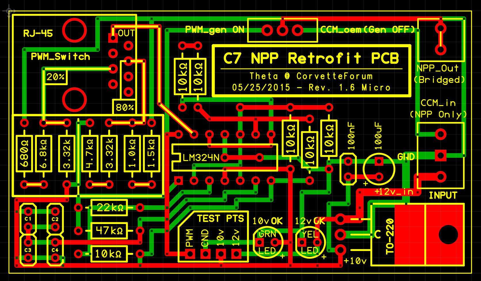
It's a new micro version - designed from scratch - (3" by 1.7" versus the 3.8" x 2.5") that reduces the size by almost 50% - it required a lot of new thought for the layout, etc. Also 100% through-hole, and no SMD/SMT soldering required. Much easier for DIYers who want a project and don't have an air station.
This new one was designed specifically for a Hammond case, utilizes a CAT5/RJ45 connection/cable hookup for the front switch, etc. It also has test points, new cap groupings, and so forth.
Suffice to say, I've been a busy boy today!
Before I go in on 50-100 of these, I want to make sure I have everything down to a science, and integrate every possible user-friendly design feature. Hopefully, this mod will be around for a long time.
There are a few commercial pieces arriving soon by a large exhaust company, but they work by way of dealing with the ESM menu and the CCM... Still not an instant override, and no way to force close the valves like this does.
Hopefully there's still a good amount of interest in this project - I'm putting my all into making it the best it can be.
Just so everybody knows, I'm not stringing this out for no reason - here's what I spent my entire day doing...
It's a new micro version - designed from scratch - (3" by 1.7" versus the 3.8" x 2.5") that reduces the size by almost 50% - it required a lot of new thought for the layout, etc. Also 100% through-hole, and no SMD/SMT soldering required. Much easier for DIYers who want a project and don't have an air station.
This new one was designed specifically for a Hammond case, utilizes a CAT5/RJ45 connection/cable hookup for the front switch, etc. It also has test points, new cap groupings, and so forth.
Suffice to say, I've been a busy boy today!
Before I go in on 50-100 of these, I want to make sure I have everything down to a science, and integrate every possible user-friendly design feature. Hopefully, this mod will be around for a long time.
There are a few commercial pieces arriving soon by a large exhaust company, but they work by way of dealing with the ESM menu and the CCM... Still not an instant override, and no way to force close the valves like this does.
Hopefully there's still a good amount of interest in this project - I'm putting my all into making it the best it can be.
Last edited by Theta; 05-25-2015 at 06:04 AM.
05-25-2015, 03:24 PM
#31
Drifting


No problem at all - you're absolutely on the list for one of the first units and set of connectors.
Just so everybody knows, I'm not stringing this out for no reason - here's what I spent my entire day doing...

It's a new micro version - designed from scratch - (3" by 1.7" versus the 3.8" x 2.5") that reduces the size by almost 50% - it required a lot of new thought for the layout, etc. Also 100% through-hole, and no SMD/SMT soldering required. Much easier for DIYers who want a project and don't have an air station.
This new one was designed specifically for a Hammond case, utilizes a CAT5/RJ45 connection/cable hookup for the front switch, etc. It also has test points, new cap groupings, and so forth.
Suffice to say, I've been a busy boy today!
Before I go in on 50-100 of these, I want to make sure I have everything down to a science, and integrate every possible user-friendly design feature. Hopefully, this mod will be around for a long time.
There are a few commercial pieces arriving soon by a large exhaust company, but they work by way of dealing with the ESM menu and the CCM... Still not an instant override, and no way to force close the valves like this does.
Hopefully there's still a good amount of interest in this project - I'm putting my all into making it the best it can be.
Just so everybody knows, I'm not stringing this out for no reason - here's what I spent my entire day doing...
It's a new micro version - designed from scratch - (3" by 1.7" versus the 3.8" x 2.5") that reduces the size by almost 50% - it required a lot of new thought for the layout, etc. Also 100% through-hole, and no SMD/SMT soldering required. Much easier for DIYers who want a project and don't have an air station.
This new one was designed specifically for a Hammond case, utilizes a CAT5/RJ45 connection/cable hookup for the front switch, etc. It also has test points, new cap groupings, and so forth.
Suffice to say, I've been a busy boy today!
Before I go in on 50-100 of these, I want to make sure I have everything down to a science, and integrate every possible user-friendly design feature. Hopefully, this mod will be around for a long time.
There are a few commercial pieces arriving soon by a large exhaust company, but they work by way of dealing with the ESM menu and the CCM... Still not an instant override, and no way to force close the valves like this does.
Hopefully there's still a good amount of interest in this project - I'm putting my all into making it the best it can be.
Sean nice to see you never gave up! Who would have thought that emulating the square PWM signal would have been so tiresome and expensive  .....great job my freind
Ron
Last edited by vetehead; 05-25-2015 at 04:15 PM.
 05-25-2015, 03:36 PM
#33
Tech Contributor
Thread Starter
Member Since: Jan 2006
Location: Saint Louis MO
Posts: 4,761
Likes: 0
Received 219 Likes
on
110 Posts
St. Jude Donor '14-'15
Thanks, guys! I'm going to reward myself with a nice drive today, then come back and post the updated circuit diagram and stripboard schematics, along with a basic Mouser parts list.
I wish I could get it even smaller, but now I'm height-limited with that RJ-45 jack. Toying with that idea for going to the front switch. The twisted pairs should allow the signals to stay nice and steady, even when running 12ft up, and 12ft back before heading out.
I think that if it gets any smaller, though, DIYers will start having issues with cramming things.
05-25-2015, 11:37 PM
#34
Great work - I love the smaller board as well.
Just to confirm - to use this and add the capability to my non-NPP car I'll need to get at least the OEM valve controllers, correct? Is there a source for these or should I be looking to get a used set that somebody doesn't need anymore?
Just to confirm - to use this and add the capability to my non-NPP car I'll need to get at least the OEM valve controllers, correct? Is there a source for these or should I be looking to get a used set that somebody doesn't need anymore?
05-26-2015, 12:04 AM
#35
Tech Contributor
Thread Starter
Member Since: Jan 2006
Location: Saint Louis MO
Posts: 4,761
Likes: 0
Received 219 Likes
on
110 Posts
St. Jude Donor '14-'15
You'll need an NPP exhaust with the extra two NPP valve actuators (in addition to your normal AFM valves).
A few people will be in luck in another week or so once I'm completely sure I'm done needing the NPP exhaust and extra valves I have here. Haven't touched any of it in weeks (since the design is all but finalized except for the connectors), but they're hard to get when you need one overnight.
A few people will be in luck in another week or so once I'm completely sure I'm done needing the NPP exhaust and extra valves I have here. Haven't touched any of it in weeks (since the design is all but finalized except for the connectors), but they're hard to get when you need one overnight.
05-26-2015, 12:35 AM
#36
Melting Slicks

Absolutely awesome.
The St. Jude's thing is a class act as well, my sister went there when I was a kid. I will always have a soft spot in my heart for what St. Jude's did for my family.
ETA: This thread makes me glad I ordered my car with NPP lol
The St. Jude's thing is a class act as well, my sister went there when I was a kid. I will always have a soft spot in my heart for what St. Jude's did for my family.
ETA: This thread makes me glad I ordered my car with NPP lol
05-26-2015, 01:31 AM
#37
Tech Contributor
Thread Starter
Member Since: Jan 2006
Location: Saint Louis MO
Posts: 4,761
Likes: 0
Received 219 Likes
on
110 Posts
St. Jude Donor '14-'15
Here's today's work/update - a USB (Type-A) port replaces the RJ45 jack for signal output. This will drop the height requirement by several cm.
It allows for a shielded cable with 24ga/28ga conductors without needing to find or work with a shielded twisted pair (STP) Ethernet cable.
My only worry is someone plugging something into it other than the Type-A to Type-A cable, but those large warnings should suffice.
Attachment 48367506
For those terrified by this, here's a better look at a rational layout, thanks to the overlay.
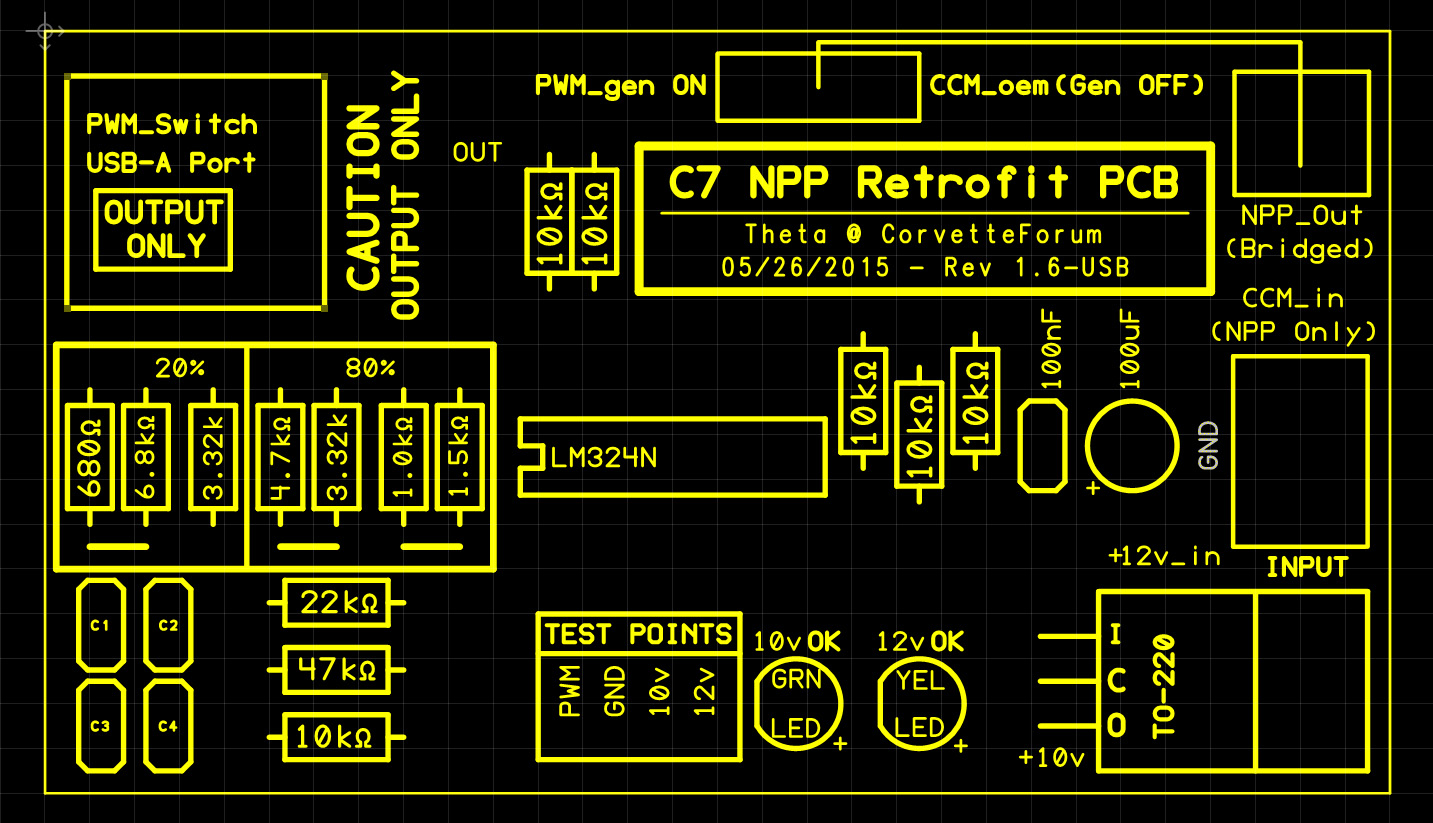
Last edited by Theta; 05-26-2015 at 02:28 AM.
05-26-2015, 02:23 AM
#38
Tech Contributor
Thread Starter
Member Since: Jan 2006
Location: Saint Louis MO
Posts: 4,761
Likes: 0
Received 219 Likes
on
110 Posts
St. Jude Donor '14-'15
All schematics/layouts have been updated to v1.6 on the front page and are current as of 05/26/15.
Hearing something like this gives me even more encouragement, knowing that even the lives of our fellow members have been touched by the work that St. Jude's does.
05-28-2015, 11:53 AM
#39
Supporting Tuner


Very, very
05-28-2015, 08:07 PM
#40
Tech Contributor
Thread Starter
Member Since: Jan 2006
Location: Saint Louis MO
Posts: 4,761
Likes: 0
Received 219 Likes
on
110 Posts
St. Jude Donor '14-'15
Thank you, sir!
I have a micro unit (33% smaller than the smaller model posted) that is ready to be posted, but due to unforeseen family circumstances, it will be a bit delayed in being posted.
I do need to hear from any of you who have purchased NEW valves directly from the factory (through a service counter or Cultrag, etc). I am wondering if these will be pre-calibrated, or if they will need to be run through a learn cycle before being usable for a retrofit. This is important, as it can impact the retrofitters without the ability to run GDS2 (99.99% of you).