When you click on links to various merchants on this site and make a purchase, this can result in this site earning a commission. Affiliate programs and affiliations include, but are not limited to, the eBay Partner Network.
HOW TO: Install Alky Control Meth Injection system in a C7
NOTE: This How-To guide is neither endorsed by or property of Corvette Forum or myself in any way/shape/form. All liability stemming from any actions taken in relation to this guide is solely placed upon the end user. (This means you!)
I have spent several weeks slowly getting pieces of my Alky Control methanol kit installed and due to missing a major component early on, was having trouble with following the directions. Some parts of the included instructions are crystal clear, and some parts could be explained in a bit more detail for the unfamiliar DIY guys that are doing this in their garage. So, I wrote this How-To guide just for those guys. I have gone into pretty good detail on everything, but if there is anything you need additional details on, please let me know. I have compiled a LOT of my own pics, but will use a few from the install manual that I feel are more than sufficient.
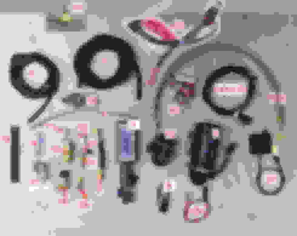
You will want to get familiar with the pieces of the kit. To make this easier, the first two pictures are of all the parts laid and numbered in conjunction with the parts list. The only thing on the parts list that was a bit confusing was number 18, which was listed as a C5 style motor plug. In either case, I don�t think matching that up matters. There were also a few parts that were included that were not on the parts list, so I have added those and gave them numbers in the upper right of the list. Please also note, you will not find references of me calling out items number 3, 4, 5, 18, as I used these when and where I felt I needed them. Also, items 26-29 are the included instructions so there are no calls out to those items. In addition to this parts list you will need to also pick up the following items:
(1) Small self-tapping screw
(1) 6 foot section of 5/32� vacuum hose
(1) Vacuum hose connecting pipe
(5) Electrical butt connectors (pipe connectors). Recommend 1 blue, and 4 red connectors.
(1) Small tube of red or blue Loctite
(1) Uni-bit drill bit (picture number 3 below). This set can be had at Harbor Freight for $15. The small one is 7/8� in size and perfect for what we need.
Here we go.. PART 1
Parts Layout:
Parts List:
Uni-bit from Harbor Freight:
Vacuum hose pipe connector:
First, we will work on getting the pump installed. You will want jack up the front of the car and put it on jack stands. It is easiest to remove the front driver�s side wheel, but you do not need to remove the front wheel if you do not want to. Simply turn the steering all the way left to gain access to the wheel well. Next we will take off the splash guard. Remove the bolts on the bottom of the car that I have circled. Note there is a hidden 10MM bolt where the arrow is.
After that, pull off the splash guard, it�s held on with clips so it pulls right off.
Next remove the plastic clip and the three torx head bolts. They are size T-15. Then remove the plastic clip that is also circled.
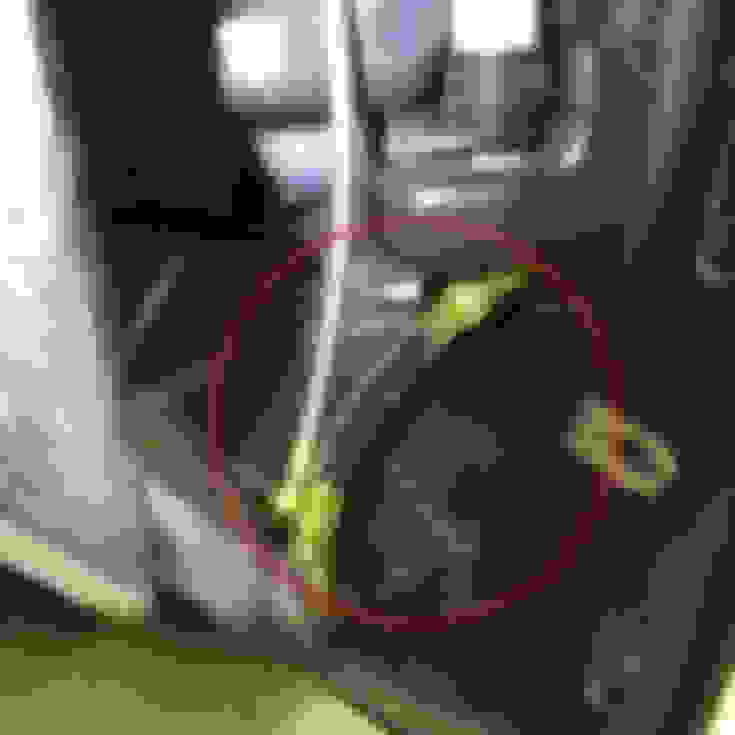
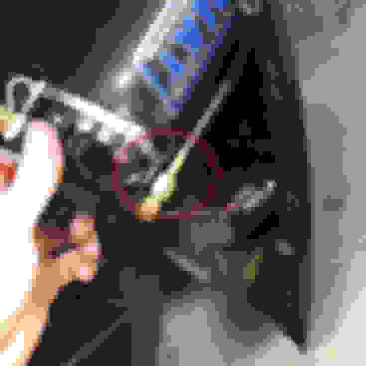
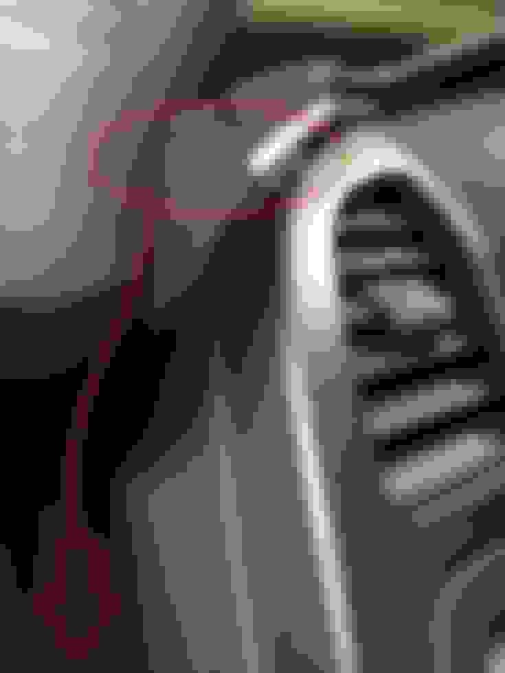
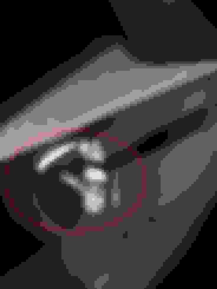
Now pull back the wheel well lining as much as you can so we can get into the fender. You should also be able to pull back the underneath of the liner to expose the bottom of the windshield washer tank. Grab your drill and the uni-bit (the smaller of the two in the package) you went and bought earlier. Here, drill a hole in the bottom of the tank WHERE I CIRCLED IN RED. I put mine a tad too far back and my line is a bit taught, so to make sure you have enough slack, do it where it circled. The bit you use should have 7/8� as the largest size. Drill all the way into the largest size. Try to clean up the hole from the plastic shavings as much as possible.
Next install the rubber grommet, and then install the tank 90* elbow (ITEM 19 ON LIST)
Make sure to remove the windshield washer fluid pump from the front of the tank, and install the plug in its place [B](ITEM 28 ON LIST)
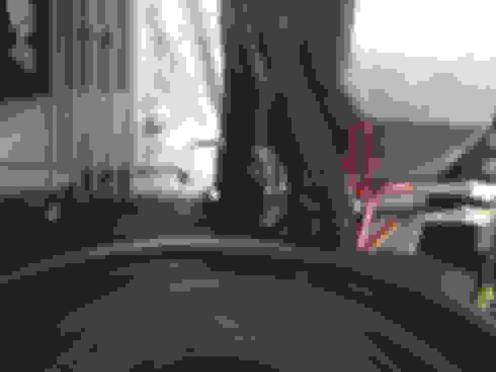
After this it is time to run the wiring for the pump and the vacuum line to the inside cabin before we mount the motor. This ensures you have enough room to get in there. See the pic below, it shows the inside of the driver foot well where the rubber grommet is. Use an X-acto knife to cut a slit into the grommet, and feed a metal hanger through until you can get it in the fender well area. This part proved to be rather tricky.
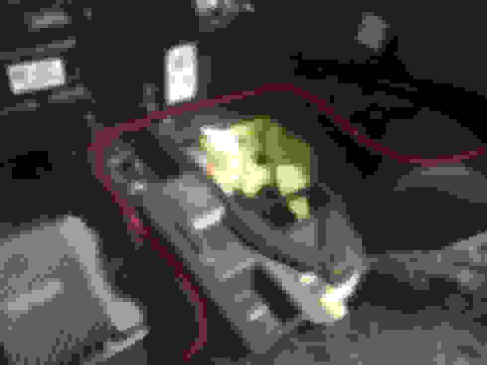
Now is also a good time to run your first 28� braided line (ITEM 8 ON LIST) from the brake booster area down to the pump area. Run both the vacuum line and the 28� braided line down using the path I have outlined below. It may take a few tried before the lines come down to the right area.
Here you will want to tape your vacuum line, and the pump shielded cable (PART OF ITEM 2 ON LIST) to the coat hanger, and pull it through to the inside of the cabin. Then go back to the wheel well area.
Next we will need to attach the 6� pump line (ITEM 7 ON LIST) to the 90* elbow you installed into the washer fluid tank. Tighten this fitting now, and do not over tighten. Remember, it is soft brass.
Now is a good time to drill a hole in the area I pictured below, which we will use for a self-tap screw. I drilled a small hole to make it easier.
Now we need to get the pump ready (ITEM 2 ON LIST). Remove this bracket from the pump, we will not need it.
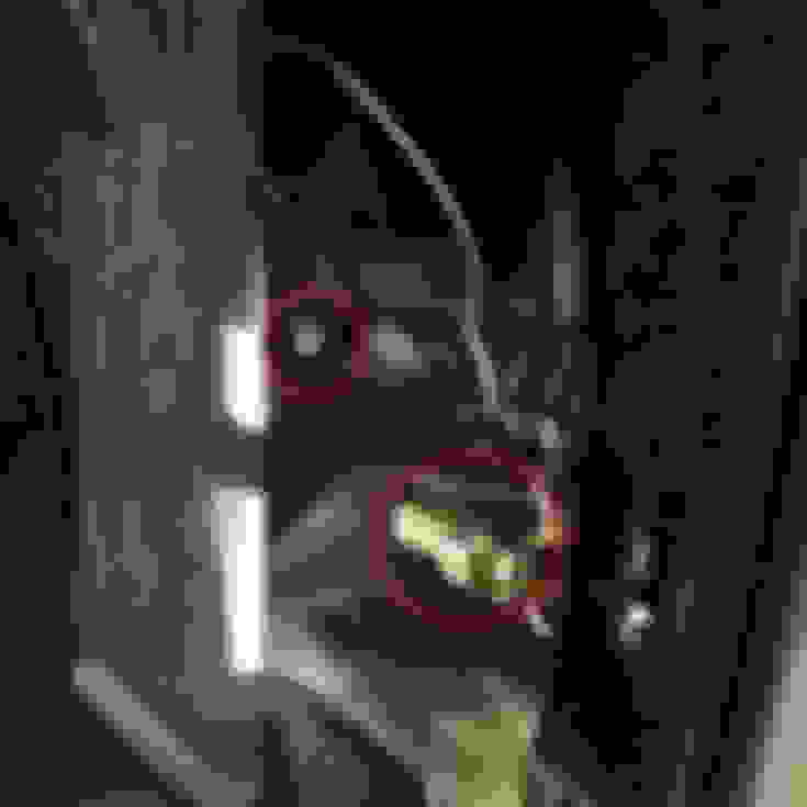
Now grab the new bracket (ITEM 15 ON LIST) and bolt it to the pump with the same screws you took the old bracket off with. Next, grab the two small 90* elbows (ITEMS 11 AND 12 ON LIST) and use some Teflon tape and wrap the threads on them. Install the smaller elbow (ITEM 12 ON LIST) to the place I have circled in blue. Make sure to install it where the tip faces up. Install the other elbow (ITEM 11 ON LIST) on the side I have circled in green. Make sure that one is oriented the same as in my picture below. After this the pump is ready to mount.
Disconnect the wire loom plastic holder as this is the hole we will use to mount our pump. Using one of the supplied stainless steel bolts with nylon nut, mount the pump loosely to this hole. (Pictured). Before you tight the mount bolt up, make sure to connect the pump wiring connector to the shielded wire we ran earlier.
Next connect the 28� braided line we ran earlier to the other side of the pump. Tighten this line now, and don�t over tighten!
Now, using a self-tap screw, connect the white wire coming off the pump to the hole you made earlier in the chassis. After this is done, you can tighten the pump mounting bolt. Afterwards, connect your tank reservoir line that you installed to the other elbow on the pump. Again, don�t over tighten!
Now we are going to install the Meth filter (ITEM 10 ON LIST). You will also need to mount bracket (ITEM 17 ON LIST). Mount the filter with the bracket to the existing bolt hole in the image. The filter has an arrow on it to indicate the flow direction. Make sure to orient it as shown below.
Using either the supplied vacuum �T� fitting (ITEM 14 ON LIST) or equivalent, install the T into the line that goes to the intake manifold port. (NOT THE VALLEY COVER PORT!) Connect the vacuum line you ran earlier to this. This is your reference line for the MAP sensor we will install later.
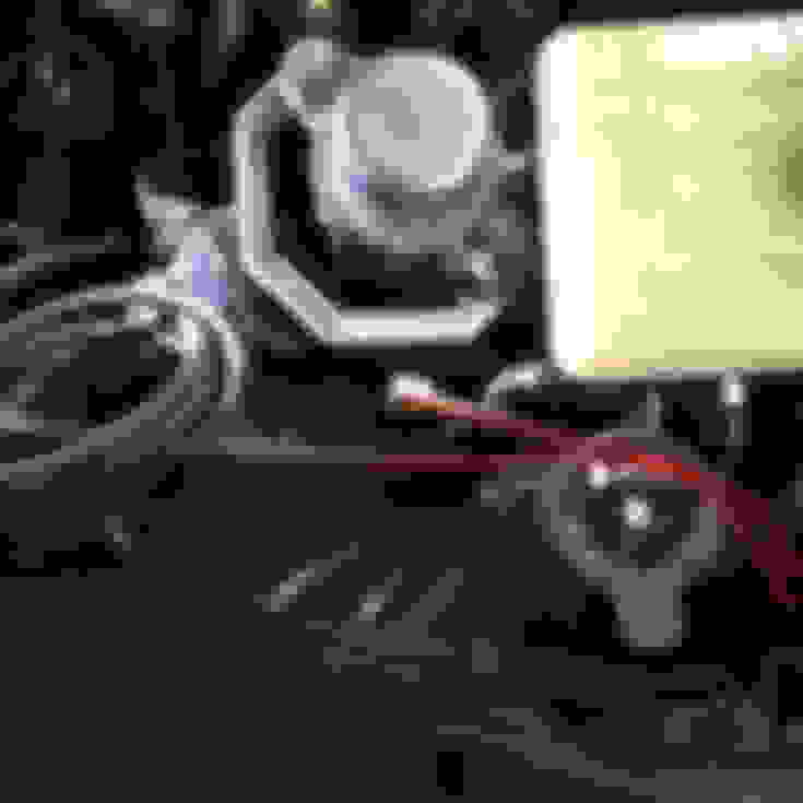
This step is more specific to my install, but I�ll explain it anyway. Here I am showing where I chose to tap into my charge pipe for the meth nozzle (ITEMS 20 AND 21 ON LIST). I am putting it in this location as on the other side of the pipe you can see I have a sensor mounted into a weld bung. This is an IAT sensor breakout, that is going to be used to tune in safeties in case of meth pump failure, or if I run out of meth while WOT. Remember, the meth nozzle hole needs to be after the MAF sensor! Drill your hole into your charge pipe (needs to be just a pinch bigger than a 3/8� bit). Be sure to clean up the edges of the hole with a file to make sure you have a smooth surface for the nozzle to seal against. The Nozzle has two washers included with Rubber on one side of them. You must unscrew the nozzle like the below picture, and then you can install it into the charge pipe. You MUST have a rubber washer on both sides of the metal of the charge pipe! No exceptions! (unless of course your blower kit uses a rubber pipe, in which case you can peel off the rubber from the washers and use just the washers against your rubber charge pipe). The Washers are hard to get onto the elbow so you will have to fight to get it installed, but once you get it on there partly, you can use the other part of the nozzle to pull the washer on by screwing the two parts together. Make sure to use some red or blue Loctite on the nozzle tip threads! You don�t want that sucker coming out while your motor is running! Also put some Loctite on the threads for the check valve (ITEM 21 ON LIST, probably screwed together with the nozzle already, if so disassemble, add Loctite, reassemble and tighten). Attach the other 28� braided line (ITEM 9 ON LIST) to the meth filter, and the other end to the meth nozzle. Also install the cap onto the washer fluid reservoir (ITEM 16 ON LIST).
At this point you are done with the under hood section of the install. You can put the wheel well back together, and take the car off jack stands.
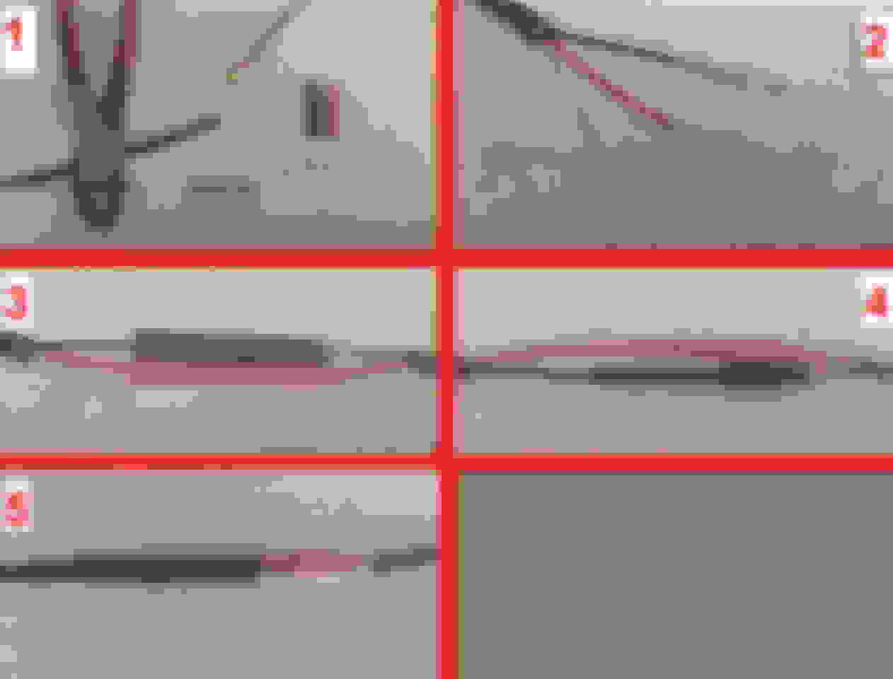
Now, we need to wire the PAC Controller up (ITEM 1 ON LIST). You will notice several wires coming out of the PAC controller. One will be a group of three wires, red, black, and white. They will have spade terminal connectors on them already. These are the wires we connect to the pump wiring we pulled into the cabin earlier. This is a good time to determine the length of wire you need, and cut off the excess. When you have done that, then strip about 2 inches of sheathing off the remaining pump wiring, and this will show you a red, black, and bare metal wire. Crimp the provided spade terminal connectors onto the three wires. It would be best to use a heavy duty set of crimpers for this! Now before you connect the wires, slip over some shrink tubing color coded for each wire as shown in the picture. Then slip over the large shrink tubing which will be used to cover all three up later. Connect the wires, and then heat the shrink tubing for each individual wire to seal it all up nicely. Then slip over the large one and heat that up to cover all the wires together. See the images below for this, following along in the numbered order.
Now we need to disassemble part of the dash to get in there easier. Remove the side panel of the center console, it just pops off. Then remove the small triangle piece show where the blue arrow is. Then take out two 7MM bolts on the underside of the knee panel on the bottom of the dash, and then take out one more 7MM bolt hiding on the left side by the door jamb. The panel is still held up by a few snap clips, which you will need to pull to get it off. Technically you are supposed to remove more of the center console to get the knee panel to clear, but I was able to finesse mine off without removing the center console.
The next thing we are going to do is mount the PAC controller and the remote controller (ITEM 27 ON LIST). I put the pack controller up between the metal bracket under the steering column and the steering column itself as seen below. It pretty much just sits there and the tension from the wires helps to keep it in place. You are welcome to mount this wherever you would like. Here is where mine is mounted. Doing it this way allows a convenient location for the wires to come out of the side as shown in the second pic.
The remote controller can be mounted almost anywhere you like. It uses a simply computer network patch cable to connect, so you can get a longer one of needed. For this guide, I will recommend you mount it on the lower right side of the dash, right underneath to keep it easy. I chose to mount mine behind the infotainment screen, but it�s a real pain to get behind there to run all the wires, so I won�t go into how I did that in this guide.
Next we will wire up the MAP sensor. Before we do that, we need to connect the first wire harness up the PAC Controller. Grab ITEM 6 ON LIST. This harness plugs right into the PAC Controller. Now grab ITEM 13 ON LIST which is the MAP sensor. The MAP sensor has three wires coming out of it. Unravel the wires, and get two of the butt (pipe) connectors and two pieces of shrink tube. Put the shrink tube on the wires first, then connect red to red, and green to green with the butt connectors. Then shrink the tubing over them to cover them up as shown below.
Next you should mount the MAP sensor somewhere under the dash. Here is a pic of where mine was put. I basically zip tied it in place. Next, use the vacuum pipe connector to connect the vacuum line you ran into the cabin to the vacuum line coming out of the MAP sensor. If it is hard to get on, use WD40 to lube the rubber. It should slide right on at that point.
Next we need to mount the �Turn-on LED� (ITEM 30 ON LIST). I mounted mine as shown in the picture below and ran the wire all the way down.
You will now want to connect the turn on LED to the PAC controller with the two color coded wires orange and brown using two butt connectors. Remember to put some shrink tube over the wire first, then connect orange to orange, and brown to brown. That is all you need to connect on that connector coming out of the PAC at this point. You can simply tie up the grey and violet wires, we do not need to use them.
Now we should have just 1 remain connector we need to get the wires connected for. (ITEM 29 ON LIST). Connect that to the only remaining connector on the PAC Controller, and run the wires down the side to the kick panel area. Here, we need to connect the black wire from this connector, AND the black wire from the MAP sensor that to the grounding bolts shown below. The wires already have O-Ring connectors on them (or they should at least) so you can simply unbolt those two bolts and slip the connectors on the bolts and bolt them back down.
After you have these connected, we need to connect the red wire that we just ran down to this area, to the red wire that goes to the relay in the back of the car. Slip some heat shrink tubing over the wire, connect the wires with a larger butt connector (this one needs a standard blue butt connector) and crimp it down. Then pull the heat shrink tubing over the connector and heat it to seal it up. Now you should tie up some of your wiring.
Hopefully you routed all your wires before connecting them together to make it easier on yourself. Here are a couple pics showing how I routed my wiring, and also where I covered the wiring with some wire loom.
At this point you will want to test to make sure things are working. Set the remote controller gain **** to 4, and turn the ignition on. You should get the RED LED on the remote controller to turn on with ignition right away. Next press the black �TEST� button. When you do so, the Turn-on LED should illuminate RED. If this checks out, you can fill the tank with meth, and check for leaks. If no leaks are found, start the car, put the gain on the controller to position 8, and push and hold the TEST button. Observe the Turn-on LED illuminates RED, and then goes GREEN since the pressure now has been established. (NOTE: IF YOU HAVE A TWIN NOZZLE SETUP, LED WILL NOT GO GREEN ON �TEST-)
At this point you should be able to re-assemble all the interior pieces you removed from the car. You are ready to try a road test. On the test bring up the boost slowly and as right as you get past 4PSI, the LED should illuminate. If it does not, DO NOT continue to test until you can figure out why the MAP sensor is not working properly to turn on the system. If it does turn on properly, then you are ready to have the car tuned for your meth injection!
Here is a pic of how I decided to mount my controller and a boost gauge behind the screen.
HOW TO CONNECT A SECOND METH NOZZLE:
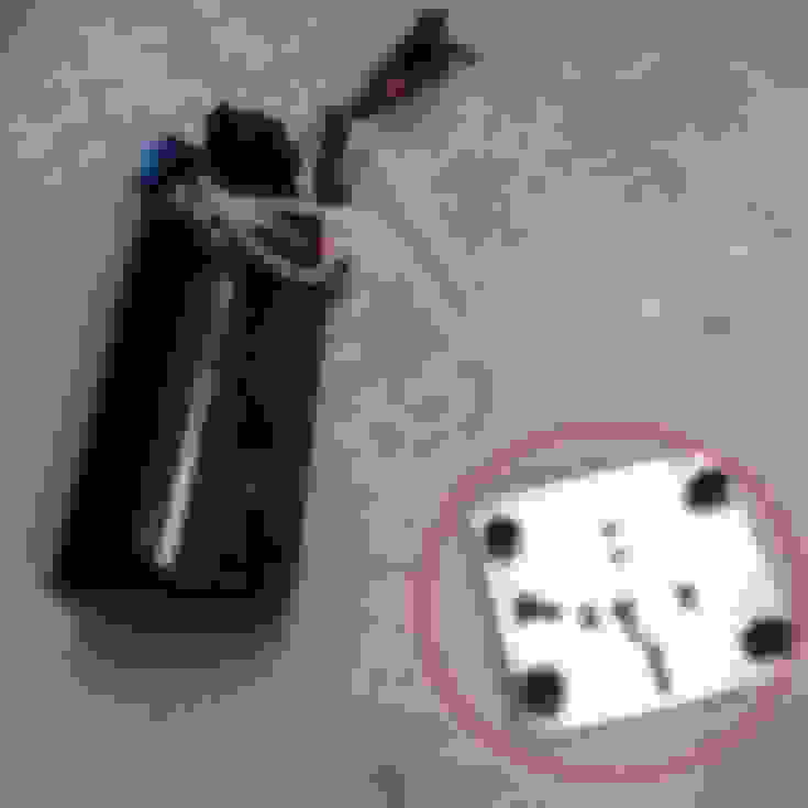
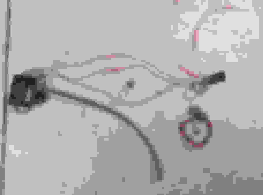
when you order the upgrade to an Alky Control second meth nozzle kit you will receive several parts (one short braided line, one slightly longer braided line, a brass "T" fitting, your second nozzle, and a large check valve.) Assemble all parts except the large check valve like the image below. Make sure that the new nozzle is connected to the shorter line, (red). The other line (yellow) will be what goes to your current meth nozzle.
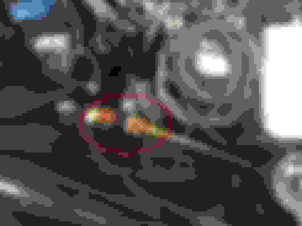
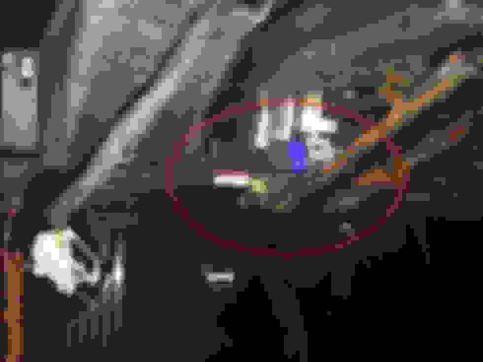
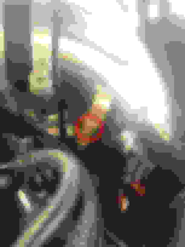
Now, disconnect the line from your existing nozzle on your setup and remove the small inline check valve (circled in red in below pic). Set this aside, you will NOT reuse this anymore since we have a new check valve which is much larger to install next.
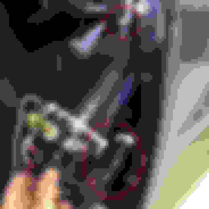
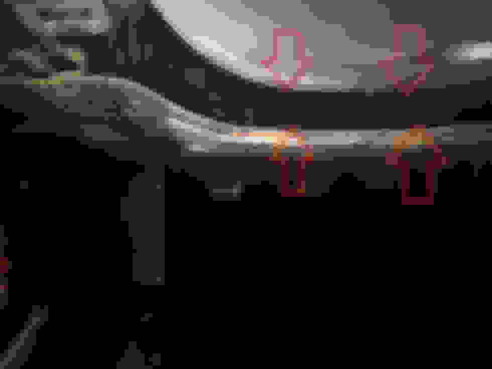
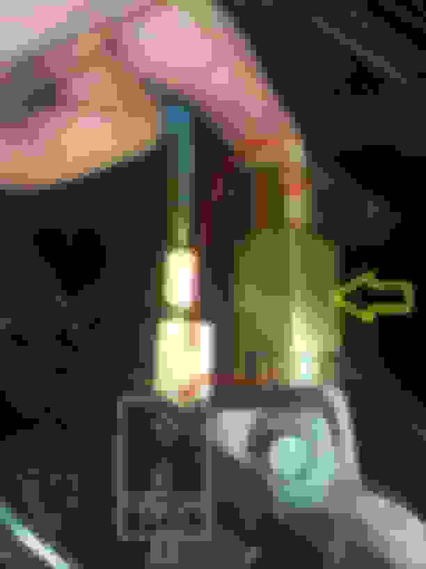
Ok now we need to connect the new inline check valve (yellow). To do this it needs to be installed on the egress side (after the flow) of the inline filter. Unscrew the large screwed on "cap" on the inline filter (the part that coverts it from the large threaded section to the small threaded section the braided line connects to), connect the inline check valve to the inline filter, and then reconnect the cap to the egress side of the new check valve, and then reconnect the braided line to it. Make sure that the flow indicator arrows look like the ones in the pic (green) Based on where mine is located, it was hard to get a picture, so I drew where my inline filter was in the pic below to give you an idea. The line with the blue arrow is the line that goes out to the meth nozzles. Again, make sure that the brass "T" fitting is assembled like I have shown in the first pic. do NOT connect the feed line for the nozzles to the middle port on the Brass T. The way it is in the pictures allows for proper flow and also helps to fit around the charge pipe better. It's also a good idea to use some blue Loctite on the connections to ensure they do not come loose.
Recommendations for tapping the charge pipe are hard to give without seeing where you chose to tap your existing first nozzle. but, if you tapped the first one at 9 O'clock, tap the second around 3 O'clock and vice versa. That's it!
Please let me know if you have any questions. Thanks!!
Now we are going to start the wiring. In the back of the car, pull up the carpet, and remove the cover over the battery, and the cover over the fuse panel. Now is also a good time to pull up the carpet by the rear cubby storage. We are also going to remove some interior panels. Remove the rear cargo shade �D� hook; it uses a Torx T-40 bolt.
Next we need to pop up the small trim piece that goes around the roof stowage mount. It is held in place by 4 snap clips.
After you get that off, simply pull the side wall panel off to expose everything. After you do this, you should be able to fold the carpet up a good amount to reveal the rear fuse panel.
Remove the large black fuse panel cover as we will be working in there for a bit. You will need to get the relay with the 12� red wire (ITEM 22 ON LIST). Here you can see where I installed it. I simply removed the bolt, picked up the fuse panel and put the relay mount on the bolt under the fuse panel and then bolted it back down.
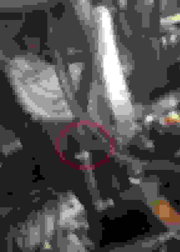
Here I am showing how the grey wire (trigger wire) gets connected. Pull out yellow fuse number 37 (they are number on the diagram which is located on the big black cover that you took out). Put the fuse through the small hole on the metal contact on the grey wire. Then reinstall fuse 37 back into its same panel location.
Remove the plastic wire look holder, and put the fuse holder onto the threaded bolt. Then reinstall the wire look holder. This will hold the fuse holder in place.
Use this bolt that I have pointed to for mounting the black ground wire to.
Attach the red wire with the O-Ring to the power lug as shown below. Don�t worry, since the car is off the relay will not allow the power through, so you won�t have sparks flying when you finish the wiring.
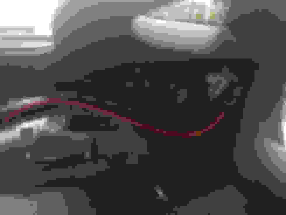
Now we are going to run the 12� red wire coming out of the relay up to the driver�s side kick panel. I run the wire over from the relay towards the driver�s side of the fuse panel area, then I route it around the trunk cubby. The I route it over the wheel well, and down the inside of the rear kick panel (the one by the seat belt). Here are some pics showing the path I took. The third pic down is showing the rear kick panel pulled away from the body. I did not take that panel off, just pulled the snap clips to loosen it up a bit.
This should get your red wire all the way up to the drivers kick panel area as seen below.
Now, we need to wire the PAC Controller up (ITEM 1 ON LIST). You will notice several wires coming out of the PAC controller. One will be a group of three wires, red, black, and white. They will have spade terminal connectors on them already. These are the wires we connect to the pump wiring we pulled into the cabin earlier. This is a good time to determine the length of wire you need, and cut off the excess. When you have done that, then strip about 2 inches of sheathing off the remaining pump wiring, and this will show you a red, black, and bare metal wire. Crimp the provided spade terminal connectors onto the three wires. It would be best to use a heavy duty set of crimpers for this! Now before you connect the wires, slip over some shrink tubing color coded for each wire as shown in the picture. Then slip over the large shrink tubing which will be used to cover all three up later. Connect the wires, and then heat the shrink tubing for each individual wire to seal it all up nicely. Then slip over the large one and heat that up to cover all the wires together. See the images below for this, following along in the numbered order.
Now we need to disassemble part of the dash to get in there easier. Remove the side panel of the center console, it just pops off. Then remove the small triangle piece show where the blue arrow is. Then take out two 7MM bolts on the underside of the knee panel on the bottom of the dash, and then take out one more 7MM bolt hiding on the left side by the door jamb. The panel is still held up by a few snap clips, which you will need to pull to get it off. Technically you are supposed to remove more of the center console to get the knee panel to clear, but I was able to finesse mine off without removing the center console.
The next thing we are going to do is mount the PAC controller and the remote controller (ITEM 27 ON LIST). I put the pack controller up between the metal bracket under the steering column and the steering column itself as seen below. It pretty much just sits there and the tension from the wires helps to keep it in place. You are welcome to mount this wherever you would like. Here is where mine is mounted. Doing it this way allows a convenient location for the wires to come out of the side as shown in the second pic.
The remote controller can be mounted almost anywhere you like. It uses a simply computer network patch cable to connect, so you can get a longer one of needed. For this guide, I will recommend you mount it on the lower right side of the dash, right underneath to keep it easy. I chose to mount mine behind the infotainment screen, but it�s a real pain to get behind there to run all the wires, so I won�t go into how I did that in this guide.
Next we will wire up the MAP sensor. Before we do that, we need to connect the first wire harness up the PAC Controller. Grab ITEM 6 ON LIST. This harness plugs right into the PAC Controller. Now grab ITEM 13 ON LIST which is the MAP sensor. The MAP sensor has three wires coming out of it. Unravel the wires, and get two of the butt (pipe) connectors and two pieces of shrink tube. Put the shrink tube on the wires first, then connect red to red, and green to green with the butt connectors. Then shrink the tubing over them to cover them up as shown below.
Next you should mount the MAP sensor somewhere under the dash. Here is a pic of where mine was put. I basically zip tied it in place. Next, use the vacuum pipe connector to connect the vacuum line you ran into the cabin to the vacuum line coming out of the MAP sensor. If it is hard to get on, use WD40 to lube the rubber. It should slide right on at that point.
Next we need to mount the �Turn-on LED� (ITEM 30 ON LIST). I mounted mine as shown in the picture below and ran the wire all the way down.
You will now want to connect the turn on LED to the PAC controller with the two color coded wires orange and brown using two butt connectors. Remember to put some shrink tube over the wire first, then connect orange to orange, and brown to brown. That is all you need to connect on that connector coming out of the PAC at this point. You can simply tie up the grey and violet wires, we do not need to use them.
Now we should have just 1 remain connector we need to get the wires connected for. (ITEM 29 ON LIST). Connect that to the only remaining connector on the PAC Controller, and run the wires down the side to the kick panel area. Here, we need to connect the black wire from this connector, AND the black wire from the MAP sensor that to the grounding bolts shown below. The wires already have O-Ring connectors on them (or they should at least) so you can simply unbolt those two bolts and slip the connectors on the bolts and bolt them back down.
After you have these connected, we need to connect the red wire that we just ran down to this area, to the red wire that goes to the relay in the back of the car. Slip some heat shrink tubing over the wire, connect the wires with a larger butt connector (this one needs a standard blue butt connector) and crimp it down. Then pull the heat shrink tubing over the connector and heat it to seal it up. Now you should tie up some of your wiring.
Hopefully you routed all your wires before connecting them together to make it easier on yourself. Here are a couple pics showing how I routed my wiring, and also where I covered the wiring with some wire loom.
At this point you will want to test to make sure things are working. Set the remote controller gain **** to 4, and turn the ignition on. You should get the RED LED on the remote controller to turn on with ignition right away. Next press the black �TEST� button. When you do so, the Turn-on LED should illuminate RED. If this checks out, you can fill the tank with meth, and check for leaks. If no leaks are found, start the car, put the gain on the controller to position 8, and push and hold the TEST button. Observe the Turn-on LED illuminates RED, and then goes GREEN since the pressure now has been established. (NOTE: IF YOU HAVE A TWIN NOZZLE SETUP, LED WILL NOT GO GREEN ON �TEST-)
At this point you should be able to re-assemble all the interior pieces you removed from the car. You are ready to try a road test. On the test bring up the boost slowly and as right as you get past 4PSI, the LED should illuminate. If it does not, DO NOT continue to test until you can figure out why the MAP sensor is not working properly to turn on the system. If it does turn on properly, then you are ready to have the car tuned for your meth injection!
Here is a pic of how I decided to mount my controller and a boost gauge behind the screen.
HOW TO CONNECT A SECOND METH NOZZLE:
when you order the upgrade to an Alky Control second meth nozzle kit you will receive several parts (one short braided line, one slightly longer braided line, a brass "T" fitting, your second nozzle, and a large check valve.) Assemble all parts except the large check valve like the image below. Make sure that the new nozzle is connected to the shorter line, (red). The other line (yellow) will be what goes to your current meth nozzle.
Now, disconnect the line from your existing nozzle on your setup and remove the small inline check valve (circled in red in below pic). Set this aside, you will NOT reuse this anymore since we have a new check valve which is much larger to install next.
Ok now we need to connect the new inline check valve (yellow). To do this it needs to be installed on the egress side (after the flow) of the inline filter. Unscrew the large screwed on "cap" on the inline filter (the part that coverts it from the large threaded section to the small threaded section the braided line connects to), connect the inline check valve to the inline filter, and then reconnect the cap to the egress side of the new check valve, and then reconnect the braided line to it. Make sure that the flow indicator arrows look like the ones in the pic (green) Based on where mine is located, it was hard to get a picture, so I drew where my inline filter was in the pic below to give you an idea. The line with the blue arrow is the line that goes out to the meth nozzles. Again, make sure that the brass "T" fitting is assembled like I have shown in the first pic. do NOT connect the feed line for the nozzles to the middle port on the Brass T. The way it is in the pictures allows for proper flow and also helps to fit around the charge pipe better. It's also a good idea to use some blue Loctite on the connections to ensure they do not come loose.
Recommendations for tapping the charge pipe are hard to give without seeing where you chose to tap your existing first nozzle. but, if you tapped the first one at 9 O'clock, tap the second around 3 O'clock and vice versa. That's it!
Please let me know if you have any questions. Thanks!!
If you followed this guide, that means you no longer have a windshield washer system in your car. If you have a NON-Z51, you are in luck. I have already written a guide that will help you to install a relocated washer tank where the dry sump tank would have gone if you had a Z51. That guide can be found here: https://www.corvetteforum.com/forums...a-non-z51.html
This is just what I needed. My Alky Control kit arrives Tuesday! I owe you a huge thanks for taking the time to document with such detail and lots of pics. Perfect! Thanks Ant!
This is just what I needed. My Alky Control kit arrives Tuesday! I owe you a huge thanks for taking the time to document with such detail and lots of pics. Perfect! Thanks Ant!
You owe me nothing Clark! I just enjoy being able to help other members. That's why I do a lot of guides.
Weird, when I did this thread on my computer all the pictures were oriented correctly. On my iPhone though most of them are rotated incorrectly, some are even upside down. Anyone else seeing that?
EDIT: Looks like photobucket jacked up my orientation. I'll have it fixed shortly.
EDIT AGAIN: picture orientation should be corrected.
At this point you will want to test to make sure things are working. Set the remote controller gain **** to 4, and turn the ignition on. You should get the RED LED on the remote controller to turn on with ignition right away. Next press the black “TEST” button. When you do so, the Turn-on LED should illuminate RED. If this checks out, you can fill the tank with meth, and check for leaks. If no leaks are found, start the car, put the gain on the controller to position 8, and push and hold the TEST button. Observe the Turn-on LED illuminates RED, and then goes GREEN since the pressure now has been established. (NOTE: IF YOU HAVE A TWIN NOZZLE SETUP, LED WILL NOT GO GREEN ON –TEST-)
At this point you should be able to re-assemble all the interior pieces you removed from the car. You are ready to try a road test. On the test bring up the boost slowly and as right as you get past 4PSI, the LED should illuminate. If it does not, DO NOT continue to test until you can figure out why the MAP sensor is not working properly to turn on the system. If it does turn on properly, then you are ready to have the car tuned for your meth injection!
Hi Antonio,
So let me understand, the "turn on LED" is the one you mounted in the upper left corner of your dash by the driver door and it turns red when the pump is activated. Then turns green when the pump sees pressure. I assume that's what the "second" white wire is for on the shielded pump connector. (must be pressure indicator wire)...
Now for my real question. When road testing you say the LED should illuminate just after 4psi. Am I to assume that it would turn red momentarily and then quickly green? Seems the system is set to initially turn "on" at 4psi? Or would this only be if you have your gain dial set on "4"?
Or is the system set to initially activate at 4psi and then gain would used to step up the pressure at the dialed in number on the controller?
Please explain and THANKS!
I haven't road tested mine just yet, that's just what the instructions say. I assume once it sees 4 PSI the MAP sensor tells the system to illuminate green right off the bat and start spraying. System is indeed set to turn on at 4PSI. I don't believe the gain **** has anything to do with the boost PSI or the activation PSI.
I haven't road tested mine just yet, that's just what the instructions say. I assume once it sees 4 PSI the MAP sensor tells the system to illuminate green right off the bat and start spraying. System is indeed set to turn on at 4PSI. I don't believe the gain **** has anything to do with the boost PSI or the activation PSI.
Julio posted this:
Well the turnon **** sets up a reference voltage whereby it compares the voltage on the green wire input. It controls when the controller activates. So decreasing the Turnon point decreases the boost level the system activates at. Or vice versa, increasing it(CW) increases when the kit activates.
So.. typically you shouldnt need the system to control knock when it activates. And... its setting is based on tuning preference. Typically a good place to be is .33-.4 of your target boost level. So if you run 10 PSI boost, activate at 3-4 PSI? This way you can roll it in. And you shouldnt have any KR with or without alcohol at .3-.4 of target.
If you want to get a little more technical.. if you probe the 12 o'clock position on the Turnon control... and you measure voltage.. that will be the voltage the kit turns on. So lets say its set to 2.70 volts. When the green wire hits 2.71 it activates the kit. A 2bar at 100 KPA=0 psi is approx 2.4 volts. Every PSI is approx .16v. So 2.72 is 2 psi boost. 2.88 is 3 psi, 3.04v is 4 psi, etc.
A separate clip from one of Julio's posts (added for ref notes for later)
Since a 2 bar is 2.4 at zero vacuum.. then having a lower turnon point will activate the pump.
I understand its now a 3 bar, and 2.2 is fine for that sensor.
When ever you turn ignition on.. that "turnon" led has to be off. It cannot come on unless your in boost. I have seen some shops actually set it to come on under vacuum and the mess that causes. In those cases wish they would simply pickup a phone and call
I also found this on a different forum:
The "turn on" **** is the boost level that the system starts spraying, should be set to 12 o'clock.
"Initial" is the starting volume of alky injected at the "turn on" point above, should be 11:30 position.
The blue "gain" **** controls the slope that the alky ramps in as boost rises. I think Julio wants you to set it on 6 and adjust boost and fuel around those alky settings. If it knocks turn up the gain.
This is awesome! Can't thank you enough for doing this. I read the instructions from Alky website and was concerned that they were not detailed enough for my level of knowledge. This seals the deal!
Can you tell me where you purchased these?
(1) Small self-tapping screw
(1) 6 foot section of 5/32” vacuum hose
(1) Vacuum hose connecting pipe
I have a ecs kit and alky kit on the way soon. Ordered Friday!
You can get all that at the auto parts store. If the don't have self tap screws there, go to Walmart or Home Depot.
This write up helped me a lot over the weekend! I've installed an Alky Control kit on a ctsv before but since it has a blower from the factory all I had to do was tap 1 green wire from the factory map sensor on the supercharger. This running a tube into the car threw me for a loop. It's barely even mentioned in the Alky instructions and I just figured he did it for a mechanical boost gauge. I spent a lot of time reaming out that grommet in the firewall. I was worried it might pinch the vacuum tube shut if the hole wasn't loose enough.
All I have left to do is drill the intake pipe and connect the boost reference line. I am unsure where to get the boost reference. The only tube I see running into the intake manifold is coming from the valley port, which is what I have the blow off valve tied into. Since it has a check valve in it to only let vacuum through i'm guessing that would not be the place to try to ref boost. Does anyone have an image of where they "T'd" into the boost ref? I don't have a catch can yet so mine doesn't look like the OP's setup.
Thank you!!
Im glad this guide helped someone! God knows I fought the install for a few weeks. Proper tapping for vacuum/boost reference shoold be done on the line coming out of the side of the intake manifold. (The one that goes to your BOV). That is how I have mine setup. Also, hope you are planning to get a catch can. Boosted applications increase the need for one. Happy motoring!
Im glad this guide helped someone! God knows I fought the install for a few weeks. Proper tapping for vacuum/boost reference shoold be done on the line coming out of the side of the intake manifold. (The one that goes to your BOV). That is how I have mine setup. Also, hope you are planning to get a catch can. Boosted applications increase the need for one. Happy motoring!
Ant
Thank you sir, i do plan to add a catch can soon. Just want to get the thing tuned this week and let my account recover a bit before buying one. Im either going with the new FSP can/breather or the Lashway setup.
Today marks 1 month from when i purchased the car. Headers, Cam, Tune done a couple weeks ago. A&A kit and AlkyControl meth kit installed this last weekend and waiting for tuning this Thursday
Are you dry or wet sump? I'm on dry and do not plan to use one unless I see the need. I will monitor it and determine if one is needed but the dry sump system already has a breather setup from factory.

 08-22-2015, 12:34 AM