
LT1 GDI owners
 12-29-2016, 05:24 AM
#401
Instructor


FYI:
As seen on the internet... care to speculate re: DI and Port Injection?
Ford's 5.0-liter Coyote V8 engine might not be long for this world. A recent report finds the Blue Oval will introduce a brand-new eight-cylinder engine during the Detroit Auto Show that will open its doors in a few short weeks.
The V8 will be a 4.8-liter unit. It will remain naturally-aspirated, but it will return better gas mileage than the Coyote engine thanks in part to the use of both direct and port fuel injection systems.
Read more: http://new.leftlanenews.com/ford-to-...#ixzz4UDlbczIQ

The following users liked this post:
911Hunter (06-16-2018)
12-29-2016, 01:59 PM
#402
Instructor

Have several threads on the intake valve coking issues with the LT4, so will make this one for the LT1.
This video does a good job of showing you what the issues are, the causes, and better understanding your new generation engine and how to prevent issues down the road. Look close and pause the video several times to see just how rapidly the intake valves are building the deposits.
https://www.youtube.com/watch?v=7Pz0zTQ1bz0
I recommend the crushed walnut shell blasting media service but the manual cleaning as shown will also work.
Now, much of this is redundant if a member searches, but I will cover it all here for the C7 crowd in one thread.
Prior to 2014, all GM V8 gasoline engines were port injection. This constantly showered the intake valves with detergent fuel (ALL gasoline in the US must have minimum mandated detergent content to keep valves clean from back prior to port injection when carbureted engines experienced this coking causing wear to valve guides and stems resulting in a needed valve job by 40-50k miles) and when the industry migrated to the port fuel injection most have grown up with valve jobs went the way of the dinosaur, that is until GDI came onto the scene to be able to meet Federal emissions and CAFE fuel economy standards. So, here is a diagram of how a port injection fuel system kept your intake valves spotless longer than the life of the engine, and why most do not remember when a valve job was part of owning a car:
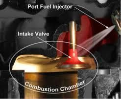
This fuel spray kept the valves cool and clean and even after 100-200k miles, a port injection engines intake valves will never have deposits on then, and therefore the valve guides and stems rarely saw wear (unless a machining error as the LS7 is known for in some instances) and the main reason for a "catchcan" was to stop the oil ingestion that caused detonation, clogged ringlands, and other issues, but never contributed to premature wear of internal engine parts and the degradation of power and economy over time like we see today with GDI.
Below shows how now, top tier fuel does nothing to improve any part of the injection or fuel system, and the fuel never touches the valves:
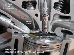
There are many advantages to GDI vs PFI, and this is mainly due to the near elimination of detonation (pre-ignition, Knock, etc.) as the fuel no longer is present through the entire intake and compression stroke where any glowing carbon spec or hot point in the combustion chamber could pre-ignite the A/F mixture. Now the fuel is not introduced until the final 10% or so of the compression stroke, and it is present only milliseconds (most of the combustion process occurs before the fuel can even touch the piston top) so we can now see far higher compression ratios, lower octane fuels, less emissions, and better fuel economy. The fuel injectors now operate at 2000 plus PSI vs the 45-55 of old PFI, so they cannot easily form ANY deposits. This renders any fuel additives, top tier fuels, etc. useless and a waste where they were of great benefit to the PFI engine.
The downside is with no fuel to keep the valves cool and deposits free, we now have a far greater issue that back in the 60's and 70's when carbureted engines had the coking and wear issues from it. AT least then some fuel cooled and cleaned/slowed deposits. Now there is zero.
So, a valve that would have looked like these pictures of a PFI engine at say 142000 miles (actual mileage of the LS engine in these pictures):
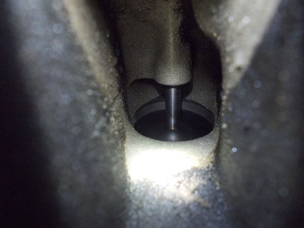

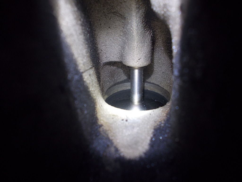
now will look like this in as little as 40k miles:
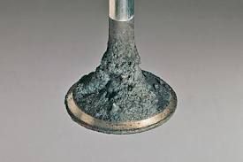
And the deposits are not like the soft carbon build up on piston tops of PFI, these are hard crystallized very abrasive deposits that are pulled into the guide with every cycle of the intake valve causing premature wear far greater that back in the carbureted days. Look close at how the stem suffers as these deposits wear on it, and the guide is the softer of the material:

These deposits are caused by more than just the oil mist present in the intake air charge, there is also several other damaging compounds that enter the crankcase as blow-by, and what you see is only part of the issue. Over time, as these hard abrasive pieces break loose, smaller ones can be forced between the piston and cylinder wall causing scouring and larger ones can get trapped between the valve and seat causing piston to valve contact and a bent valve or worse:
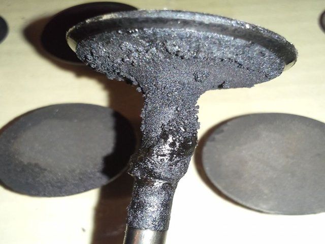
Look closely at the valve above, and you can see on the left portion of the stem where the tulip meets a large chunk broke off and caused the damage. The owner bringing the car in to the dealer they did diagnose it right away so a good amount of driving was done after this occurred and you can see the additional build-up over where the chunk broke off.
Now, anyone with a 2014 or 2015 LT1 have doubts this is occurring in your engine? It only takes 5-10 minutes and minimal tools to remove your intake manifold and look at YOUR valves up close and see the severity at the miles you have on yours.
Now, how to prevent this?
The "catchcans" of the past that worked well with a PFI engine, only trapped 15-50% or so of this oil mix that bakes onto the valves so they may slightly slow the coking, but will do little to stop it. You must use one of the very few that catch and trap 95-08% of this mix, and those are true air/oil separation devices. ColoradoSpeed and Elite Engineering having two of the most effective period currently on the market (extensive test results available to any that wish to see how the other "catchcans" stack up).
You must stop as much of this as possible.
Now, looking around I see several well intended solutions, that are not well thought out, and the most common is to delete the PCV system, and just rout your clean and dirty side lines into a tank with breather, or worse, open hoses near the ground (where one due to the Venturi effect will suck up dust and dirt directly into the tank and the engine).
The PCV system does far more than satisfy emissions. Back when the Fed mandated the PCV system in the mid 60's, it was rare for an engine to go much over 50k miles before excessive wear of all internal parts resulted in an entire rebuild being needed. And even though the PCV system was mandated for emissions alone (before that draft tubes were the norm, similar to the breathered Tanks seen today) but it did not take long for the industry to see these same engines were going 100-150k plus miles with little internal wear. Studying this found that the PCV system was constantly removing the damaging combustion by-products from the crankcase as soon as they entered and were still in a gaseous state. If allowed to settle, these mixed with the oil contaminating it and causing wear and failure eventually. The PCV system was removing these allowing the oil to stay cleaner longer, and the damaging compounds to accumulate at a minimal amount. So, defeating your PCV system is a sure way to cause a shortened engine life and accelerated wear. The compounds causing this wear and damage are as follows:
Water vapor
Unburnt fuel
Abrasive soot and carbon particles
Sulfuric acid, and more.
70% plus of internal engine wear is caused by the particles in the 2-5 micron size, and as your oil filter can only trap down to 15 microns in size, if these are allowed to accumulate in the engine oil and crankcase, you are drastically shortening the life of your engine. ANY defeat of any critical function of your PCV system is going to allow this, and/or worse. Allowing pressure to build and vent is also damaging over time to the rings, ringlands, and cylinder walls due to "ring flutter" and other damage caused by ring instability, so you want to pull vacuum/suction at all times, and NOT ever vent pressure as it must first build until it can vent, and no good comes from crankcase pressure.
So, the systems that deal with this properly are addressing the dirty, or foul side with a truly effective separation device, and w special separator that is used on the "clean, or fresh side" and add a secondary evacuation suction source for when the engine is under acceleration and no intake manifold vacuum is present.
I'll stop here for now and invite questions and discussion on the GDI engines in general, and more specific GM's and what they have done to reduce the ingestion, and why this affects EVERY single GDI engine made in the World from every auto maker. Understanding and making the correct emissions compliant, not effecting warranty changes to ensure you get the longest enjoyable life out of these awesome engines.

This video does a good job of showing you what the issues are, the causes, and better understanding your new generation engine and how to prevent issues down the road. Look close and pause the video several times to see just how rapidly the intake valves are building the deposits.
https://www.youtube.com/watch?v=7Pz0zTQ1bz0
I recommend the crushed walnut shell blasting media service but the manual cleaning as shown will also work.
Now, much of this is redundant if a member searches, but I will cover it all here for the C7 crowd in one thread.
Prior to 2014, all GM V8 gasoline engines were port injection. This constantly showered the intake valves with detergent fuel (ALL gasoline in the US must have minimum mandated detergent content to keep valves clean from back prior to port injection when carbureted engines experienced this coking causing wear to valve guides and stems resulting in a needed valve job by 40-50k miles) and when the industry migrated to the port fuel injection most have grown up with valve jobs went the way of the dinosaur, that is until GDI came onto the scene to be able to meet Federal emissions and CAFE fuel economy standards. So, here is a diagram of how a port injection fuel system kept your intake valves spotless longer than the life of the engine, and why most do not remember when a valve job was part of owning a car:

This fuel spray kept the valves cool and clean and even after 100-200k miles, a port injection engines intake valves will never have deposits on then, and therefore the valve guides and stems rarely saw wear (unless a machining error as the LS7 is known for in some instances) and the main reason for a "catchcan" was to stop the oil ingestion that caused detonation, clogged ringlands, and other issues, but never contributed to premature wear of internal engine parts and the degradation of power and economy over time like we see today with GDI.
Below shows how now, top tier fuel does nothing to improve any part of the injection or fuel system, and the fuel never touches the valves:

There are many advantages to GDI vs PFI, and this is mainly due to the near elimination of detonation (pre-ignition, Knock, etc.) as the fuel no longer is present through the entire intake and compression stroke where any glowing carbon spec or hot point in the combustion chamber could pre-ignite the A/F mixture. Now the fuel is not introduced until the final 10% or so of the compression stroke, and it is present only milliseconds (most of the combustion process occurs before the fuel can even touch the piston top) so we can now see far higher compression ratios, lower octane fuels, less emissions, and better fuel economy. The fuel injectors now operate at 2000 plus PSI vs the 45-55 of old PFI, so they cannot easily form ANY deposits. This renders any fuel additives, top tier fuels, etc. useless and a waste where they were of great benefit to the PFI engine.
The downside is with no fuel to keep the valves cool and deposits free, we now have a far greater issue that back in the 60's and 70's when carbureted engines had the coking and wear issues from it. AT least then some fuel cooled and cleaned/slowed deposits. Now there is zero.
So, a valve that would have looked like these pictures of a PFI engine at say 142000 miles (actual mileage of the LS engine in these pictures):


now will look like this in as little as 40k miles:

And the deposits are not like the soft carbon build up on piston tops of PFI, these are hard crystallized very abrasive deposits that are pulled into the guide with every cycle of the intake valve causing premature wear far greater that back in the carbureted days. Look close at how the stem suffers as these deposits wear on it, and the guide is the softer of the material:

These deposits are caused by more than just the oil mist present in the intake air charge, there is also several other damaging compounds that enter the crankcase as blow-by, and what you see is only part of the issue. Over time, as these hard abrasive pieces break loose, smaller ones can be forced between the piston and cylinder wall causing scouring and larger ones can get trapped between the valve and seat causing piston to valve contact and a bent valve or worse:

Look closely at the valve above, and you can see on the left portion of the stem where the tulip meets a large chunk broke off and caused the damage. The owner bringing the car in to the dealer they did diagnose it right away so a good amount of driving was done after this occurred and you can see the additional build-up over where the chunk broke off.
Now, anyone with a 2014 or 2015 LT1 have doubts this is occurring in your engine? It only takes 5-10 minutes and minimal tools to remove your intake manifold and look at YOUR valves up close and see the severity at the miles you have on yours.
Now, how to prevent this?
The "catchcans" of the past that worked well with a PFI engine, only trapped 15-50% or so of this oil mix that bakes onto the valves so they may slightly slow the coking, but will do little to stop it. You must use one of the very few that catch and trap 95-08% of this mix, and those are true air/oil separation devices. ColoradoSpeed and Elite Engineering having two of the most effective period currently on the market (extensive test results available to any that wish to see how the other "catchcans" stack up).
You must stop as much of this as possible.
Now, looking around I see several well intended solutions, that are not well thought out, and the most common is to delete the PCV system, and just rout your clean and dirty side lines into a tank with breather, or worse, open hoses near the ground (where one due to the Venturi effect will suck up dust and dirt directly into the tank and the engine).
The PCV system does far more than satisfy emissions. Back when the Fed mandated the PCV system in the mid 60's, it was rare for an engine to go much over 50k miles before excessive wear of all internal parts resulted in an entire rebuild being needed. And even though the PCV system was mandated for emissions alone (before that draft tubes were the norm, similar to the breathered Tanks seen today) but it did not take long for the industry to see these same engines were going 100-150k plus miles with little internal wear. Studying this found that the PCV system was constantly removing the damaging combustion by-products from the crankcase as soon as they entered and were still in a gaseous state. If allowed to settle, these mixed with the oil contaminating it and causing wear and failure eventually. The PCV system was removing these allowing the oil to stay cleaner longer, and the damaging compounds to accumulate at a minimal amount. So, defeating your PCV system is a sure way to cause a shortened engine life and accelerated wear. The compounds causing this wear and damage are as follows:
Water vapor
Unburnt fuel
Abrasive soot and carbon particles
Sulfuric acid, and more.
70% plus of internal engine wear is caused by the particles in the 2-5 micron size, and as your oil filter can only trap down to 15 microns in size, if these are allowed to accumulate in the engine oil and crankcase, you are drastically shortening the life of your engine. ANY defeat of any critical function of your PCV system is going to allow this, and/or worse. Allowing pressure to build and vent is also damaging over time to the rings, ringlands, and cylinder walls due to "ring flutter" and other damage caused by ring instability, so you want to pull vacuum/suction at all times, and NOT ever vent pressure as it must first build until it can vent, and no good comes from crankcase pressure.
So, the systems that deal with this properly are addressing the dirty, or foul side with a truly effective separation device, and w special separator that is used on the "clean, or fresh side" and add a secondary evacuation suction source for when the engine is under acceleration and no intake manifold vacuum is present.
I'll stop here for now and invite questions and discussion on the GDI engines in general, and more specific GM's and what they have done to reduce the ingestion, and why this affects EVERY single GDI engine made in the World from every auto maker. Understanding and making the correct emissions compliant, not effecting warranty changes to ensure you get the longest enjoyable life out of these awesome engines.
12-29-2016, 07:09 PM
#403
Race Director

Member Since: May 2004
Location: Raleigh, NC
Posts: 16,664
Received 1,194 Likes
on
1,053 Posts
St. Jude Donor '15

Why would that fix this issue?
01-03-2017, 10:32 AM
#404
Instructor
This is what i have been saying. I think in general DI engines are going to show more carbon build up, but I simply do not believe to the rate at which coSPEED2 says it is.
GM has mass amounts of DI engines on the road. wont be surprised if just about every engine they make is now DI. At 30-50k miles they are going to see MASS amounts of carbon build up(according to this thread). GM would have warranty claims like crazy if all the engines have major build up at 40k miles. Lets not forget GM also for years had the 100k mile warranty. According to coSPEED2 at 40k miles the valves are already toast. at 90k miles the car shouldn't be turning out. Yet they do.
Heres where i stand. I am waiting for high mileage LT1 and LT4 pictures to start rolling in. I also plan on checking my valves at 20k miles. If i see real data that supports coSPEED2 claims I will be a real believer.
Recently a Z06 LT4 owner posted at clean valve at 10k miles. a owner, not a vendor. its funny, vendors were pushing catch cans on the LS engines. Yet they are not DI.
 How do we know that the owner didn't simply overfill his crankcase or dry sump? It's not hard to do! One or two photos of valves coking up doesn't prove anything........Like you said, It would have to be massive reports and customer complaints.
01-03-2017, 11:27 AM
How do we know that the owner didn't simply overfill his crankcase or dry sump? It's not hard to do! One or two photos of valves coking up doesn't prove anything........Like you said, It would have to be massive reports and customer complaints.
01-03-2017, 11:27 AM
#405
Race Director
Member Since: May 2004
Location: Raleigh, NC
Posts: 16,664
Received 1,194 Likes
on
1,053 Posts
St. Jude Donor '15
You should see the BMW boards... you're pretty much guaranteed to need to have the intake valves walnut blasted by 50K miles on their DI engines.
01-03-2017, 01:01 PM
#406
Melting Slicks

There is no question that oil and contaminates pass from the valley connection to the intake manifold on LS and LT engines. The contaminates are mixture of moisture, burnt fuel, unburnt fuel, oil, etc. If nothing else, they dilute the fresh air/fuel mix. Might as well separate them if you don't mind installing and maintaining an air/oil separator.
01-04-2017, 09:17 AM
#407
Instructor
There is no question that oil and contaminates pass from the valley connection to the intake manifold on LS and LT engines. The contaminates are mixture of moisture, burnt fuel, unburnt fuel, oil, etc. If nothing else, they dilute the fresh air/fuel mix. Might as well separate them if you don't mind installing and maintaining an air/oil separator.

Last edited by Chevette!?!?; 01-04-2017 at 09:19 AM.
01-04-2017, 03:59 PM
#408
Melting Slicks
Mine has never been overfilled and upon inspection there was oil in the tube between the valley and manifold. That was all I needed to see to decide a catch can would be a benefit and I had one laying around to experiment with.
The following users liked this post:
COSPEED2 (01-19-2017)
01-19-2017, 04:20 PM
#409
Melting Slicks
Thread Starter

Bumping this back up as there is some good discussion going on here.
01-19-2017, 09:56 PM
#410
Safety Car

02-15-2017, 10:05 AM
#411
Melting Slicks
Thread Starter
06-23-2017, 01:01 PM
#412
Melting Slicks
Thread Starter
For any that are interested, some more data from a 2 year study conducted by one of the Worlds most respected Lubrication labs:
Final results of 2 year study
Here is a brief summary of what was documented in the 2 year testing by one of the Worlds largest Lubrication companies:
"The XXX system was tested on the most severe engine on the road toady as far as GDI related issues. The testing was performed on a fleet of new vehicles including GM and others, but they only focused on the results of the Ford Ecoboost engines as they experience the most severe GDI related effects.
First, here is how the testing was performed. Each vehicle has been run through proper break-in and driven over 10k miles to eliminate ring seating variance, etc.
Then the vehicle would be run for app 5-6k miles on their premium full synthetic oil and a sample drawn...this is without our system installed. Then, our system is installed on that same oil fill, no oil change, and then run another 4-5k miles and another sample drawn and at that time oil is drained and changed.
Here are some examples on just viscosity and fuel dilution:
Miles on vehicle: 55060 Ford 3.5L Ecoboost
Miles on oil when sample drawn: 5,943 Fuel dilution: 5.6% Viscosity @40*C: 45.71 Viscosity @100*C: 8.76 (Now, vehicle is driven and sample drawn below)
Miles on oil when sample drawn: 9,411 Fuel dilution: 3.86% Viscosity @40*C: 46.98 Viscosity @100*C: 8.82 (Even AFTER saturation well above the industry 5% threshold where oil is considered "condemned" or no longer able to protect the engine our system was able to not only prevent further fuel dilution and viscosity degradation, but actually IMPROVED each taking the oil that was no longer usable and extending it's ability to protect far longer.
Now, that was the least dramatic result....some were as high as fuel dilution levels of 7% to above 12% by 5k miles (cold start enrichment in cool/cold conditions adds to dilution far quicker) and we were able to bring those levels down even more dramatically, in some cases by as much as 50% less after a few thousand miles WITH our system installed.
Other benefits documented: Average fuel economy increases of 1-3 MPG due to a cleaner burn with the contaminants removed from the PCV vapors as more energy is released with just air and fuel present during the combustion process. This also shows a significant reduction in knock retard as pre-ignition is reduced and combined with a cleaner burn in the combustion chamber, reduces emissions as well as improves fuel economy.
As our system converts the PCV system to full time evacuation and flushing VS part time as the OEM systems come and retains a closed emissions compliant system.
This prevents the stagnant periods of operation when the contaminants and combustion by-products that enter as blow-by and are the primary source of oil contamination and our system greatly reduces this by removing these at all times the engine is running utilizing 2 separate evacuation suction sources, the intake manifold vacuum for when reversion pluses are not canceling it out (during acceleration or hard operation no evacuation suction is present stock), and using the Venturi effect when accelerating or running high RPM/throttle.
On GDI engines (most all Automakers are now 100% GDI) we have the additional benefit of reducing the intake valve coking issue by as much as 85% (we cannot eliminate all as these engines use variable valve events to allow back filling of exhaust gasses back into the port behind the valves to be re-burnt emulating the outdated EGR system/valves of old.
To summarize, the benefits:
Engine life extended to 2-3 times expected life w.out the system installed.
Fuel economy increase of 1-3 MPG average.
Extended oil drain intervals allowing from 50% to 100% longer use of oil reducing pollution from improperly disposed of drain oil.
Reduced tailpipe emissions. As we remove most of the compounds causing a incomplete burn in the combustion process reducing the amount of emissions.
Reduction of intake valve deposits by as much as 85%.
The downside is these MUST be drained and the contents collected disposed of properly as with any drain oil. every 5k miles as a rule (will vary from engine to engine depending on state of piston ring seal to cylinder walls).
We do have a system that never needs to be emptied or service for in excess of 100k miles, but not released yet that could be retrofitted at a later date.
What is in the contents of the system that are removed from the engine crankcase vapors?
Here is a sample after a 2400 mile drain after being spun in a centrifuge to separate all for analysis:
70% was acidic water (the sulfuric acid produced during the combustion process cannot be separated from the water).
23% was raw fuel (GDI engines introduce fuel at well over 2,000 PSI and this pushes many times the amount past the rings of old port injection systems that operated at 45-50%)
and only 7% was actual oil, and it is saturated with abrasive particulate matter.
This other wise would have remained in the crankcase mixing with and contaminating the engine oil, and also contaminating the intake air charge reducing the over efficiency of the engines combustion process.
On Fleet applications, depending on miles driven the fuel economy and oil drain extensions give a ROI in app 6.7 months average. As a whole, these could drastically reduce overall emissions as well as tremendous savings on fuel cost and usage."
Quite a bit of data on area's we had not been focusing on before. Very eye opening.
The systems they used were the Patented design that Colorado Speed Premium cans uses as well as the Elite E2-X series.
06-23-2017, 10:51 PM
#413
Pro

 06-24-2017, 10:01 AM
#414
Melting Slicks
Thread Starter
06-24-2017, 12:10 PM
#415
Melting Slicks

Member Since: Nov 2009
Location: Klein TX
Posts: 3,037
Received 906 Likes
on
570 Posts
2023 C6 of the Year Finalist - Unmodified
2022 C6 of the Year Finalist - Unmodified

Could you post drawings or pictures showing what's inside the latest cans and how they separate liquids from blow by gasses?
06-24-2017, 01:33 PM
#416
Melting Slicks
Thread Starter
Do this test with ANY can claiming to be the"best" and you will see. There is no better, more fair test period and anyone can conduct the same. Watch the entire video and pay attention to the very last 5 minutes.
Last edited by COSPEED; 06-24-2017 at 02:01 PM.
06-24-2017, 04:29 PM
#417
Melting Slicks
Member Since: Nov 2009
Location: Klein TX
Posts: 3,037
Received 906 Likes
on
570 Posts
2023 C6 of the Year Finalist - Unmodified
2022 C6 of the Year Finalist - Unmodified
Thanks for posting the video. Very informative, but it didn't quite address the question I meant to ask.
When I asked "what's inside?" I meant what parts are inside the current patented RX and Elite cans, not what gunk do they separate from blow by gasses. Baffles, chambers, scotch brite pads, and wads of metal shavings have been used by different manufacturers in the past, with varying results.
So, to put it another way, what is the state of the art in catch can design now?
06-24-2017, 06:37 PM
#418
Melting Slicks
Thread Starter
Thanks for posting the video. Very informative, but it didn't quite address the question I meant to ask.
When I asked "what's inside?" I meant what parts are inside the current patented RX and Elite cans, not what gunk do they separate from blow by gasses. Baffles, chambers, scotch brite pads, and wads of metal shavings have been used by different manufacturers in the past, with varying results.
So, to put it another way, what is the state of the art in catch can design now?
When I asked "what's inside?" I meant what parts are inside the current patented RX and Elite cans, not what gunk do they separate from blow by gasses. Baffles, chambers, scotch brite pads, and wads of metal shavings have been used by different manufacturers in the past, with varying results.
So, to put it another way, what is the state of the art in catch can design now?
The patented design each of those cans uses the incoming vapors enter a center inlet tube that runs into a large coalescing chamber where the tube is perforated allowing the vapors to evenly disperse throughout all of the coalescing media. Then they exit the bottom of the coalescing chamber and enter the main condensing and accumulation chamber before they have to evenly pass the lower disc baffle providing the maximum contact with the outer wall for further condensing as they enter the secondary condensing chamber. From there, them slow allowing time to further condense any remaining suspended compounds before again being forced past the upper disc baffle that again forces the vapors to make maximum contact with the outer walls one final time before entering a completely separate outlet chamber where they again can slow before exiting either outlet. The primary outlet using the IM vacuum, and the secondary using the Venturi generated vacuum present just in front of the TB when accelerating or at WOT. The dual check valves open and close o automatically default to use the strongest suction source available at any operating mode.
Also. each system utilizes the Cleanside Separator to address the 2nd point of ingestion adding app. 3" of vertical height from the direct path the OEM clean/fresh side hose provides and has a separate coalescing chamber internally to trap and prevent ingestion upstream of the TB.
Hope this helps! This is the type of dialog our goal is to generate.
06-24-2017, 06:51 PM
#419
Melting Slicks
Member Since: Nov 2009
Location: Klein TX
Posts: 3,037
Received 906 Likes
on
570 Posts
2023 C6 of the Year Finalist - Unmodified
2022 C6 of the Year Finalist - Unmodified
Thanks for the quick reply, just what I was looking for!
Any diagrams/drawings/pictures of the innards? Btw, what is the coalescing media?
Any diagrams/drawings/pictures of the innards? Btw, what is the coalescing media?
The following users liked this post:
COSPEED2 (06-25-2017)
06-25-2017, 10:51 AM
#420
Melting Slicks
Thread Starter
"An oil water separator, or OWS, contains coalescing media. This media provides a suitable surface for oil droplets to meet and grow, or coalesce, into larger droplets."
Or for more technical info:
http://www.coalescingconcepts.com/pr...dia-design.php
Last edited by Steve Garrett; 06-25-2017 at 11:29 AM.