When you click on links to various merchants on this site and make a purchase, this can result in this site earning a commission. Affiliate programs and affiliations include, but are not limited to, the eBay Partner Network.
How to install: DIY American Racing Mid-Length Headers
First an introduction. I will be 67 yrs. old in a couple of months so am not a limber 30 or 40 something anymore. I am also not a professional mechanic. I worked in a Chysler/Plymouth dealership service department for 4 yrs in the early '70's after my discharge from the military. I built my own drag race car, a '66 Plymouth Satellite, and have also built a few engines but they were all prior to the computer controlled ones. I have always done my own wrenching and the Navy sent me to the Ford Service school prior to my discharge. So I do have automotive mechanical experience but it's old school. I have a MaxJax 2 post lift in my garage so I can lift the car up to 4 ft. off the ground. I'll post a picture later of my setup including a pic of my tool cart I wheel under with me. It helps limit the times I need to come out for tools.
I have decided to write this thread because there seems to be very little DIY information out there for installing headers There is one video where they installed long tubes, not much detail though, and Pfadt has written instructions for installing their long tubes but there is absolutely nothing on the American Racing mid-lengths. What information there is conflicts with other information. Such as, you need to remove the starter, no you don't. You need to remove the fuse box, no you don't you can do it all from the bottom. You need to remove the dry sump oil lines, no you don't. You put the header in from the top, no you don't you put them in from the bottom. So this thread is an actual step by step of my installation of ARH mid-length 1 3/4" headers with cat pipes on a 2016 Z06. I'll be taking & posting pics as I go. After todays installment there will be a delay of between 2-3 weeks while I wait to get the headers back from the ceramic coater. I want to extend an invitation to anyone who has installed the mid-length headers themselves to please offer up any suggestions, tips, or experiences you have so they can be included in this thread and applied during my installation during that time. I am sure there are either current members or future members that will find your offerings useful should they try to do a similar install themselves.
I am also not going to get into dyno numbers since that always seems to generate disputes and disagreements and that is not what this thread is about. I will tell you my car dyno'd at 582 whp with the Borla x-pipe and nothing else. I am also going to do some sound clips before and after. So, hear we go.
This really is going to be from the beginning. After completing and paying my income taxes last month and the realization that they didn't get it all, I decided to take my Corvette to the next level. Some of you have seen my Z06 or the pictures I have posted but I am going to start with a description of the car.
I purchased a 2014 Stingray, cpe, TR in June 2014. My dealer knew I was interested in a C7 Z06 and in May 2015 he called and offered me his first allotment for a 2016 Z06. I jumped on the opportunity and it was ordered a couple of days later. I decided to do NCM delivery and my 13 yr. old son and I took possession on July 16th and drove it to Oregon from Bowling Green.
Since then I have done a bunch of appearance mods which I am not going to go into in this thread. Performance wise; It has an AFE cai, Carbotech brake pads front & rear, Borla ATAK over the axle and catless x-pipe wrapped with DEI Titanium header wrap.
I know, I have posted those same pics before but sometime in the future a new member will read this thread and ask for a pic so I just included it now.
I don't track or street race. I just drive it and do put it in local car shows and cruise in's for the fun of it. It has won several awards including: Best 2000 & up, Best '85 & Newer, 2- Best Corvette, Best in Show, & last weekend at Suburban Chev's Spring Cruise In, Best C7.
Here is my favorite show pic:
So that brings everyone up-to-date and where I am starting now. I also want to say I love the Borla exhaust. The sound is amazing as is the quality and customer service. After much thought I decided to install a set of headers and started reading and googling everything I could find on headers for a C7. Since I don't abuse the car, at the top of my list was not to void the warranty. I know the owner of my dealership and his son who is the General Manager. I also am on a first name basis with the Service Dept. Manager & staff. I discussed the warranty situation with them and was told that unless my mods were a direct result of a failure, ie. the air filter element comes apart and is inhaled into the engine, as long as I did not mess with any of the cars computers I was good to go. I also wanted to deal with a reputable fabricator with proven customer service.
With that information the only header and the one most often recommended by this forum's members, requires no tune, that meets the warranty criteria & has customer service equal to David Borla is Steve at American Racing their 1 3/4" mid-length with cats. With that I began searching for a good price. They ranged from $1,405 to over $2K. Obviously I tried the cheapest first. Three vendors had them on the internet for the $1,405. Two of them immediately told me their website was wrong and their price was $1,750 & $1,795. The third actually placed the order but called me the next day, apologizing profusely but said that was well below their cost and there must have been a price increase at ARH. They did offer to sell them to me for $1,685 including shipping which was still less than any other price so I placed the order on 4/26. They said ARH told them they would ship the following week which they did. They were drop shipped directly from ARH on 6/6 & I received them today.
During the wait I researched what other things I would need to do a quality, 1st class install. The first thing that came to mind was header bolts. There is no question the top automotive fastener company in the country is ARP so I gave them a call. I was connected to their technical dept and chatted with one of their technicians about this project and the car. ARP makes a specific head bolt for the LT1/LT4. I asked about high temp. anti-seize & he recommended their Extreme Assembly Lube with a temp. to 2000 degrees. He did not try to sell these to me but gave me the correct part #'s for each. A search on Amazon found both at a reasonable price.
When Massdrop did their recent group buy for DEI header wrap I purchased a 50' roll of Titanium header wrap with the plan of wrapping the OEM down pipe before & after the cats. I did not however get the spark plugs boots then. Another search on Amazon and I found a DEI kit with 8 Titanium boots also at a reasonable price.
I have a real concern about the uncontrolled under hood heat. The stock exhaust manifolds have heat shields bolted to them to keep the heat off of the plastic and electrical parts like the main fuse box, connectors, & wiring. I have read where header manufactures frown on header wrap but ceramic coating is ok. Thus I set out to find a local company that could do this for me. I found one about 30 minutes away and was quoted around $400 & a 2-3 week waiting time to coat them in satin aluminum, 2100 degrees. I didn't want the polished and felt there was too much black in there already.
That brings me to today. ARH ships by UPS, signature required. I had the shipment held at the UPS depot which opens at 10:00 am and I picked it up myself. Kept me from waiting around all day for them to show up.
The shipment showed up in an ARH box which UPS had managed to smash which is when I had my first panic attack.
Panic attack #2. I stand the box on end to pull the staples out and finally get a good look and what does it say:
"Camaro Muffler" WHAT! Please don't let there be a Camaro muffler in there.
Nope, nice try Steve. You almost got me.
During my search for information I read a thread by a forum member who had purchased a used set of ARH long tube headers. He thought he was missing some parts when his purchase arrived but really had no idea because no one had a packing list. So here are some pics of what's in the big box.
The big piece of white paper on the left is the packing list. I will detail the contents later. The piece of red paper says to not use the factory, OEM, cyl. head to exhaust gasket but to only use the gasket supplied with the headers. I have read multiple times during my research to not use the supplied gaskets but to use the OEM ones. So now I don't know which to use. This is one of the reasons I decided to write this preface so those who have done this project can offer their experiences, tips, & suggestions before I actually do the install.
I wanted to post some pics of the headers themselves. The quality of the welds, workmanship, & materials is top notch. If you have seen the Borla exhaust systems you know how high the quality is with them and these are at least equal. I can hardly wait to hear Borla & ARH sing together.
The final pic is of the other pieces I assembled to do the install. I will give a detailed parts list with #'s and the price I paid. I will not be using the DEI header wrap. My original intention was to wrap the cat pipe before and after the cat but there is simply not enough room. I also decided not to ceramic coat this pipe especially the cat, because I did not want to possibly contaminate the cat material on the inside.
I think there should be a C7 "How To" Section with moderator approved DIYs so people can reference that section for their desired project.
That said, I think having a lift for a header install is key. From what I've seen, going through the bottom is the best way to do it.
I wasn't sure but figured the mods would set it where it belonged. Right now it really hasn't started the DIY yet until I get the headers back from coating. I wanted to ask for member input for now & share what I have learned.
I agree, the lift is going to make it much easier. Thank you.
I would suggest talking to one of the many shops about the things you might run into where there are contradictions. Looking fwd to reading your install.
Could the cat pipes be coated only on the outside?
Thanks for asking. I can elaborate a little on the coating process. They apparently soak the parts to be coated in a solution after which they are blasted with some sort of material before they are sprayed. I worried about the soaking and blasting material and how those materials might affect the inside cat material so I decided not to coat them.
There has also been talk on the forum about locking too much heat inside the cat, that it needs to release some of the heat so it doesn't get too hot internally.
Instead I am going to get the DEI blanket to seal the cat heat away from the starter and dry sump oil lines. The blanket has standoffs built in so it doesn't lay directly on the cat and allows air to circulate around the cat but blocks the heat from radiating to surrounding components.
Interesting though, as I write this I am watching Engine Power on Power Nation and they are building the Factory Five 818. They just ran it on the dyno and in the view of the engine they have wrapped the entire exhaust including the cats with DEI header wrap. This is another one of those confusing things I discussed. I am going to ask ARH their opinion.
I know several vendors offer coated y-pipes with cats. You might instead call a couple of the businesses that do this such as Jet-Hot and Calico Coatings.
Also, my personal preference for header bolts are Stage 8 locking fasteners.
I know several vendors offer coated y-pipes with cats. You might instead call a couple of the businesses that do this such as Jet-Hot and Calico Coatings.
Also, my personal preference for header bolts are Stage 8 locking fasteners.
Thanks for all the info you're sharing.
I actually did discuss this with the coater. Their response was that they could coat it but I also understand they get paid by selling their service. In this case $28/ft. I also considered the Stage 8 but couldn't find the LT1/LT4 specific set so I went with ARP. I should have called them though. Thanks.
Well fellas, this project took a big turn this week but I am going to pick up where I left off with shielding the heat from the cats. DEI makes a C7 specific cat heat shield. They sell for around $80 each. The high flow cats that come with the AR headers are 4" wide and about 4" in diameter. After doing some searching on the internet I found that DEI also makes a product called Titanium Pipe Shield part #010454. It is made to install lengthwise on an exhaust pipe such as on a motorcycle. It has the same SS mounting tabs/standoffs as the C7 cat shields DEI makes. It measures 4" wide x 12" long. Problem is the mounting tabs are positioned to mount the shield on the pipe lengthwise not around a 4" diameter cat. I noticed however the tabs are attached to the shield with a single pop rivet which I figured would allow the tabs to be rotated 90 degrees. The best part is I found these on Amazon for $28.51 ea. vs. $80 ea. for the C7 specific ones. Ordered 2 from Amazon Prime free 2 day shipping due to arrive last Wednesday.
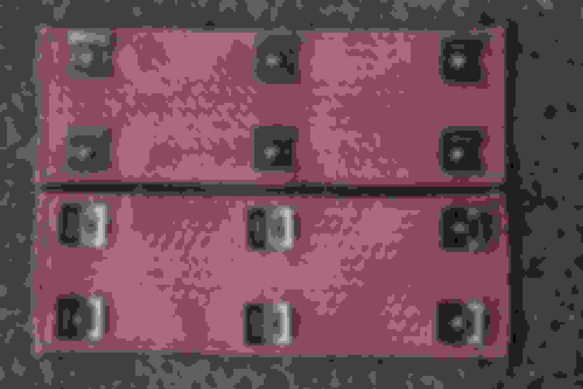
Arrived on time and this is how they are packaged.
Out of the box. You can see the mounting tabs are facing the wrong direction.
A little gentle persuasion and rotated 90 degrees. Bottom one has been rotated.
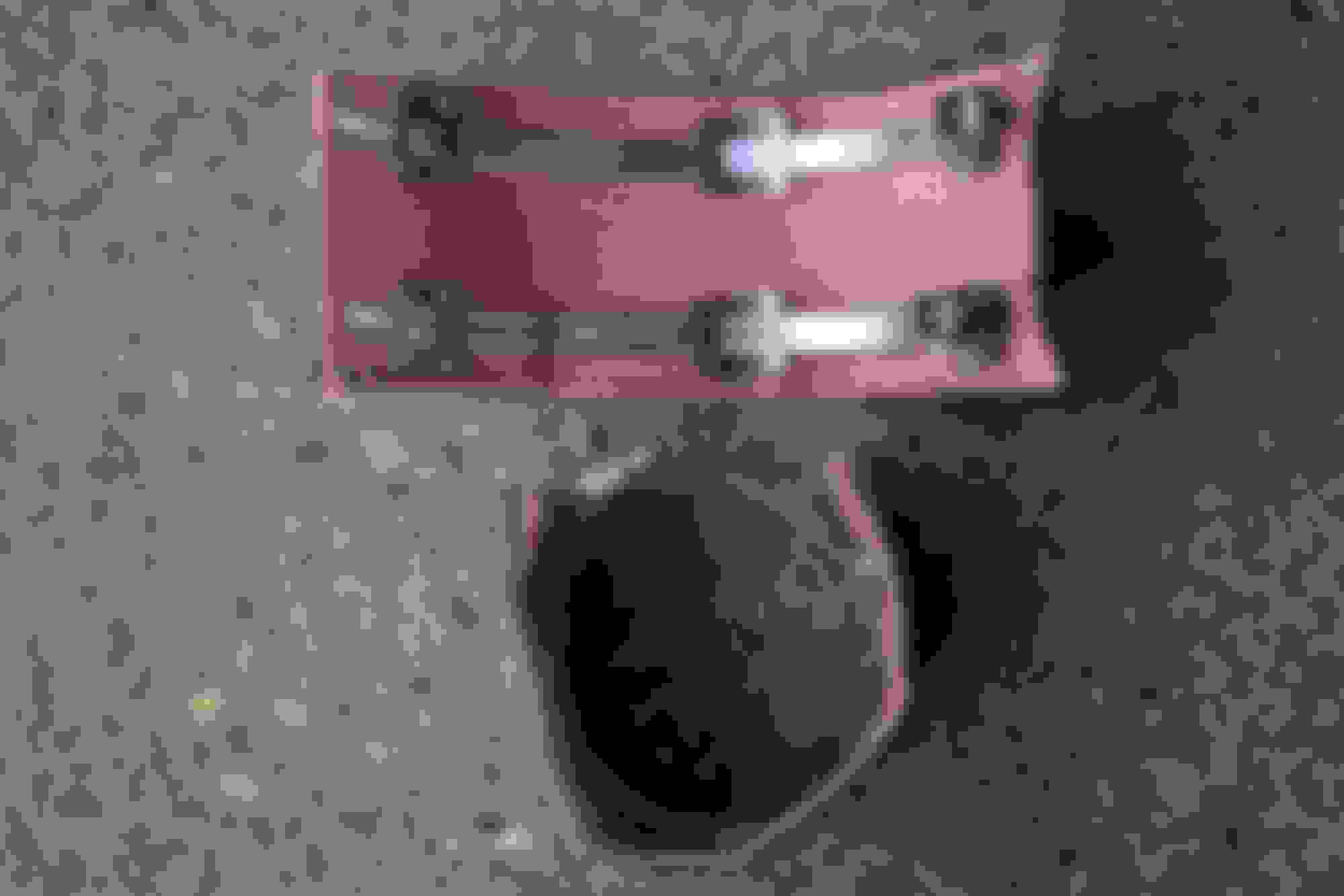
These come with 3" dia. SS screw hose clamps which are too small to go around the 4" dia. cat so off to Home Depot plumbing section to get 4" ones. A little over a $1 ea. and then they look like this.
They don't cover the entire cat but that's fine. I positioned the gap facing down so water doesn't get trapped and it still allows the cat to cool dissipating the heat down instead of onto something important.
This might be a good time to mention that extension on the O2 sensor bung. I wondered why this was there since the OEM cat pipe doesn't have it. Thought maybe it had to do with which application, Stingray or Z06, the headers were being installed on so I called Steve at ARH. Steve was very helpful. He explained the high flow cats allow the gases to pass through so fast the secondary O2 sensor doesn't have time to do it's job. Extension allows the gases to pause long enough to get a reading so if you are still going to use the secondary O2 sensors you need to leave these in place.
As I am finishing this up. I get a call from the ceramic coater. They had originally told me it would take 2-3 weeks to coat the headers. I have always felt it is a good idea to establish a good relationship with vendors I do business with. I let them know how I will be using their product. In this case I told them about my Z06 and that I would be installing the headers they were coating on it. They were real excited to learn about and see the car when it is done. Soooo.....they put the headers on the fast track and they were done in 2 1/2 days & ready to pick up. Quick drive 40 miles and here is what they returned to me. Cost out the door, $450.
Time to get the car on the lift and start the disassembly.
After positioning the car on the lift, I started on the driver's side. Coil cover first, 2 torx screws and disconnect the breather tubing going into the valve cover. wiggle the cover out. Remove the plug wires. Not an easy task. They come off the coils ok but are snapped onto the spark plugs. They are not easy to get a good grip. I used a small pry bar in the grove on the metal shield around the spark plugs. While applying a little outward pressure with the pry bar and gentle steady pulling on the squared edges on the connector they all eventually popped off. Removed the spark plugs as the header flange is above them and if you try dropping the exhaust manifold down without removing them I guarantee you will be buying some new plugs. I removed 2 of the manifold heat shield bolts while there. The 3rd I couldn't reach from the top. I sprayed the manifold bolts with Blaster and went to work on the passenger side while they soaked.
The passenger side looks like a nightmare. I started by disconnecting the plastic tubing and the various connectors. The vent in the valve cover is the most difficult but the procedure on how to remove it is covered by Theta in the "How to" threads. I did not completely remove any of the tubing but just moved them out of the way. Coil cover is next, just 2 torx screws.
You will need to know this next part if you ever plan on doing any work one the spark plugs.
You are now staring at the fuse box. Disconnect the negative battery cable and make sure it doesn't or can't fall back onto the battery. Remove the cover on the top of the fuse box. In several places I have read you can remove the fuse assembly at this point. On my '16 Z06 you first need to lift the little cover on the back side, towards the rear of the car, and remove the nut that secures 2 cables with terminals on the ends, to the box. Lift them up and move them off the stud. There are 2 handles, 1 on each end, which are held down by clips on each end. Release the clips and move the handles towards the middle of the box, then straight up, then back towards the center a short distance while you lift up. The entire box should come loose and lift free of the tray underneath.
You are now looking at the fuse box tray with the wire connectors attached.
Don't let this scare you. On the far left you can see the 2 terminals you need to remove from the stud on the fuse box. Sorry for the blurry pic but look at the blue/green connector on the lower right. On the top right corner of the green plastic part you can see a small green tab. Each of these connectors has a similar tab. I used a small screw driver to release this tab while you slide the entire thing as one piece towards the outside, right or left, of the tray. They slide in a track on the bottom of the tray and should come out fairly easily.
This is the green/blue connector and you can see the release tab on the upper right corner. I studied this for several minutes trying to figure out what and how much of it came out of the fuse tray before is spotted this tab and started playing with it, pushing, pulling, and finally sliding it and it came out very easily. You will also notice 2 little tabs on the other end. When you reassemble these fit in little holes in the center of the tray. When you slide the connectors into their groves these tabs go into their respective holes and the tab you released snaps back into place.
You will also notice a nut in the center of the tray. There are 2 more. One is by the silver tube on the lower right. The other is not in the pic but it is at the lower left bottom side of the pic. You will also need to lift the little tab that holds that silver tube in it's mount on the tray and a black plastic tube that sits in a grove on the bottom side of the tray. At this point the tray is free and you just need to wiggle and maneuver it free of the mounting studs and other stuff in the way. It's a little move difficult to re-install it because the wire harness connectors keep getting in the way.
Once the tray is out the spark plugs, their wires, manifold bolts, & heat shield bolts can all be removed. Not that difficult.
At this point I decided to call it a night and start under the car the next morning.
I did bring all of the plug wires in the house with me and was going to install the DEI spark plugs boots on them. I played with those for 2 hours trying to get the small end of the boots over either end of the plug wires and finally gave up.
Quit for the night and will tackle it again in the Thursday morning.
Before you start this project make sure you have a set of 6 point sockets in 3/8" & 1/2". The 12 points will round corners off of these bolts and nuts real quick and then you're screwed.
Before I quit the night before I raised the car and gave the O2 sensors & the cat pipe to exhaust manifold studs and nuts a good soaking with Blaster. I began by removing the big tunnel brace and then separated the x-pipe from the cat pipes. Unbolted the rear x-pipe mount and let the front of the x-pipe drop. As I said in the beginning, I already have a Borla x-pipe and didn't see a reason to remove it for the ARH install so I just let it hang. Starting with the driver's side there are 4 studs with nuts bolting the cat pipe to the bottom of the exhaust manifold. Here are a couple of pics with these removed so you can more easily see what I am talking about.
This shows the entire driver's side assembly, the passenger side is very similar, you will be removing. Looks easy right?
You can see the 2 outboard studs with nuts. Take note of the one on the left. It is not your friend on either side.
Here you can see all 4 studs, 2 inboard and 2 outboard. You can also see the 3 bolts that hold the heat shield on the manifold. I read somewhere that removing this would give you more room to move the manifold around. Yea, right. The driver's side would not come out without the manifold coming with it. The passenger side pretty much fell out.
This is a close up of the 4 studs. Note, the ends are hex shaped. I put a small socket on these and removed them all before trying to drop the manifolds out. I was having trouble removing one of the nuts so I put the socket on the end of the stud and gave it a twist. It came right out. Go figure.
So now the trouble maker. The forward outboard stud on the passenger side. I had to take a beer break after fighting for 2 hours just to get something on the nut. The suspension/frame is directly below it and there is not enough room for a deep socket and a ratchet. The stud is too long for a standard 1/2" drive socket to fit on it. Swivels or extensions are of no use, too much of an angle. I was prepared to go buy what I think they call a pass thru socket & ratchet set the next morning. This is a special socket and ratchet that has a hole thru the center of both so that the stud passes right thru each and the socket fits onto the nut. What I finally did was remove the right front tire. There is maybe a 2"x3" hole in the wheel well that looks directly at that stud. I put the 1/2" drive socket on the nut then inserted the ratchet into the socket until it bottomed out on the top of the stud. Using a pipe on the ratchet handle I applied increasing steady force until it moved. There is no room for taking big stokes at it so just one or two clicks until it was free and finally it came off.
I am going to get me one of the pass thru socket and ratchet sets. I know Craftsman has them and if you decide to do this project I'd invest in one before you start.
I couldn't really get to the O2 sensors until the cat pipe dropped down. The plugs on the driver's side are attached to a little mount with one bolt to the bell housing. I couldn't really see how to unplug the connectors with it so high up so I removed the bolt and let the bracket come down. On the end with the wires going to the sensor there is a very small square hole. I slid a real small flat screw driver into the plug pointed at that hole. I then used a flat bladed screw driver and pried the plug from the connector until it moved. Pulled gently on the wires and the plug separated from the connector. Did the same procedure for the remaining 3 O2 sensors and the cat pipes were free.
Finally time for the manifolds. Dropped the car back down & removed the 5 manifold bolts. The rear ones were a little difficult but not bad. I let the manifolds drop down and raised the car back up.
Passenger side: It fell out pretty much as soon as I looked at it.
Driver side: Stubborn and heavy. I just kept trying moving it around, getting different angles, remembering there are wires in the area, until I really couldn't see what was holding it up so I just gave it a good tug and out it came.
Time to get the headers in place.
Driver's side: Went up and in pretty easy.
Passenger side: Tried angling the front of the header up and pushing it towards the front of the car. Only went so far but the back of the flange kept getting hung up on something which I couldn't see from under the car. Lowered it down and tried again from the top. Got a little further and then hung up again at the rear. Finally saw it was hung up on a bundle of wires on the firewall. I moved them out of the way as best I could and then gave a firm tug and up it came. Headers were now in place..
If you haven't really paid much attention prior to now it would be a real good time to do so beginning right now.
I stated before I am using ARP stainless steel header bolts. Dis-similar metal have a tendency to "gall" when screwed together. If your nuts, bolts, or screws gall you're f'd. There is nothing you can do to get them apart. They will gall just by starting to screw them together and then you cannot back them back out or tighten them the rest of the way in. If you keep trying you will break them off and if that happens you are in big expensive trouble. I have had this happen even with the lug nuts on my Chev. K3500 pickup but the worst metal for this is stainless steel. I have started stainless steel bolts into stainless steel nuts and they galled not even half way to tight. They had to be cut off. I have also had stainless steel screws gall when mounting something on my fiberglass boat.
In this install I am using stainless steel bolts threaded into an aluminum head. This is a combination that could lead to a disaster if done improperly. If the bolt seizes it will be impossible to get it back out. If it breaks off you will probably be buying a new head. The only way to do this properly is to use a good quality anti-seize compound on the bolt threads. This is why I got the ARP Extreme Lube/Anti-Seize. It needs to be used on all of the threads involved in the rest of this install. GM even used it on the threads of the header bolts when the engine was assembled. I can easily see it on the bolts I took out.
With that said, I put a thin coat of ant-seize on threads all 10 of the header bolts. Slipped the header gasket between the head and header paying attention to the stamped instructions on the gasket, "Header" & "Down". Holding the header and gasket I inserted a bolt thru both in the center hole and loosely started it in the hole in the head. Then alternating front & back I started the remaining 4 bolts making sure I also captured the hole in the gasket with each. I left these all very loose turning each of them in only 3 or 4 threads until I had all of them started. The reason for this is the hole in the flange is a little larger than the bolt. If you tighten them as you go there is a chance the holes may move too far forward or back and somewhere along the line the holes may not line up and the bolt won't start. If you leave them loose the flange can move until all 5 are started. I then snugged them down but was really able to turn them all in with my fingers. With the combination of the lube and the quality of the threads on the ARP bolts I was able to turn them with ease using just my fingers.
Using the instructions I found for installing PFADT long tubes, I torqued all of the bolts to 11 ft. lbs. on the first pass and 18 ft. lbs. on the final pass. Don't forget these bolts are going into aluminum do don't get carried away or you will strip the threads out of the head.
Ok, headers are in from the top side. I reinstalled the spark plugs and wires making sure I could either hear or feel the connector "snap" onto the plug. Re-installed coil covers,the fuse box tray, fuse box, all of the plastic tubes with no screws, bolts, or nuts left over on top so all was good.
Raised the car back up.
Installed all for O2 sensors in the cat pipes. I actually did this when I removed them from the OEM pipe so I wouldn't get them mixed up. So there was a little bit of an issue with the driver's side secondary O2 sensor. If left attached to the mounting bracket it was too short. Removed the mounting bracket from the bell housing, released the connectors from the bracket and it reached just fine. I reinstalled the bolt in the bell housing and discarded the bracket. I ran the O2 wires behind some other insulated wires by the firewall and everything was good.
Passenger side was no problem at all.
I did not connect the cat pipe to the header at the ball joint until I had all of the sensors installed, connected, and wires run. There is just no room once the cat pipes are bolted up. When you connect these, once again leave everything loose because you are going to have some adjusting to do and if you tighten now you'll need to take it all loose again. Don't forget the anti-seize because all this stuff gets very hot and if you ever try to disassemble this in the future it may be very difficult.
Put the band clamp on the other end of the cat pipe and slide the connector for the x-pipe on afterwards. Line the x-pipes up with the ends of the cat pipes and start the bolts leaving everything loose enough so you can move it around.
First thing I looked for was to make sure the O2 sensors were not hitting anything and had plenty of clearance. If not twist the cat pipe until they are clear. Take a look at the ball joint where the header and the cat pipe join. Try and move the cat pipe until it contacts the header evenly all the way around. At this point I installed the bolts on the 2 flanges and just snugged them up enough I could still move the cat pipe if necessary.
I re-installed the x-pipe hanger and using a jack, jacked the front of the x-pipe up so I could install the tunnel brace. I noticed the cat pipe was actually in contact with the tunnel brace. I also notice the flanges holding the ball joint together were very close to the starter on one side and the out board frame on the other. I twisted the flanges around until the bolts were about at 1:00 and 7:00 o'clock & snugged them down again so they wouldn't move but I could still twist the pipe.
I moved jack closer to the cats and jacked them up putting some tension on them and then put a pry bar between the band clamp and the tunnel brace prying the cat pipe and x-pipe up and away from the tunnel brace. I actually saw and felt it give as the pipes moved to a different position and I now had 3/8" of clearance between them and the tunnel brace.
I tightened the x-pipe/cat pipe flanges first, then the header/cat pipe flanges and finally the band clamps. Removed the jack and everything stayed in place with no apparent clearance issues.
You can see in the pic how well engineered these are. They fit around everything perfectly. You can also see the need for heat management. There is not much room between the starter, dry sump oil lines, and cooler.
I also forgot to mention that I removed those diagonal aluminum braces. Just 2 bolts each to insure they won't interfere with the OEM stuff or getting the ARH in place. You will also need to unbolt the dry sump oil lines. I drained the oil from the bottom of the engine by removing the drain plug on the front of the "oil pan" then removed the bolts from the oil lines one at a time and let them drain. You will need to plug the openings on the engine and the lines because they will continue to drip and make a mess. I was surprised that only about 5 quarts of oil drained out. Don't forget to top off the oil again when done.
The next 4 pics show how I clocked the flange plates to get clearance all the way around.
This pic shows the clearance between the x-pipe, cat pipe, and tunnel brace. You definitely need this much clearance. I'll tell you why in my post test drive review.
So everything is back in place and ready for start up. I have made a short video but don't know how to post it right now so you'll need to wait. All I can say is when it fired it was like a AA/fuel car lighting off. A loud air piercing "CRACK" and this wonderful deep sounding rumble. I could feel it in my chest. A quick rev and the same thing. I absolutely love the sound. I let it run for a short time, checked all the gauges, no CEL, & no leaks.
Backed out of the driveway and idled in 1st down the street & there is this fantastic rumble. Made it out of the neighborhood to a country road. Manual shifting the A8. Loving the sound but the car is completely changed. Not only does it sound different, it revs & shifts different also. It's loud, 2 road workers give me as I go by. I say thanks by going half throttle. Holy crap! Sounds like a Sprint Cup race. Drive it about 5 miles & head back home. Same road workers now give me double . Returned home checked again for leaks all is good.
Two hours later head out to a cruise-in. All's good until I hit 1500 rpm and I get a loud vibrating noise which I can also feel in the gas pedal, floor, & console. Obviously there is contact between the exhaust and floor somewhere at the beginning of the tunnel. Upon return from the cruise-in I put it back on the lift. Sure enough the gap I once had between the cat pipes and tunnel brace has vanished. Went to loosen all the flange bolts to readjust and they were already loose. WTF, I assume cycling through a heat cycle things got loose. Loosened everything reset the clearance. Tightened and re-torqued and all is good again. Drove the car over the weekend but I think I'll re-torque them again just to be safe. My suggestion here is to drive it after the install, get it good and hot, let it cool down and tighten again. I think I am also going to re-torque the header bolts.
I have some sound clips as soon as I figure out how to post them. Took the car to a car show over the weekend. Took a 1st place for "Coolest Cruiser". I was asked to start it several times which produced an immediate reaction of huge smiles from everyone, including the county sheriff's deputies who were there with their new Mustang & Dodge Daytona. They came over and talked to me with big smiles and commented on how great the car sounded. Said they did not expect it out of a new Corvette.
I am extremely pleased with the sound coming from my car now. It is in every aspect everything I have ever wanted. Any questions, feel free to ask.
Thanks for posting all if the installation info. I was going to ask how it sounds but you covered that too. Sounds like it is quite a bit louder than stock.
Thanks for posting all if the installation info. I was going to ask how it sounds but you covered that too. Sounds like it is quite a bit louder than stock.
I'm still trying to figure out how to post a video clip but from what I can see so far I need to sign up on YouTube. Not something I really wanted to do.
Yes, sign up to YouTube and upload the video, then click share, embed, then copy the link provded into your forum post. Very easy to do YouTube... it's all pretty painless.
Nice work, BTW. If I ever decide to mod my C7 I'd probably go this route.
Originally Posted by C7 x 2
I'm still trying to figure out how to post a video clip but from what I can see so far I need to sign up on YouTube. Not something I really wanted to do.
Gonna give this a try. Opened a YouTube account and downloaded this video. This is the pre-ARH sound clip with the Borla ATAK & x-pipe cold start. Sorry, I didn't realize the sound would exceed the mic in the camera. I'll try to do better with the post-ARH video.

 05-13-2016, 11:54 PM


 as I go by. I say thanks by going half throttle. Holy crap! Sounds like a Sprint Cup race. Drive it about 5 miles & head back home. Same road workers now give me double


