
Oil catch can & clean side oil/airseparator tech discussion.
 09-01-2015, 04:05 PM
#21
Melting Slicks

Thread Starter


Going to try and copy and past here so not sure the images will transfer.
Here goes:
Part 1:
C7 Z06 Elite Engineering E2-X Air/Oil separation
system installation guide
The issue with the LT4 supercharged engine and the oil ingestion via the PCV system into the intake air charge has made this solution a bit more involved. With the earlier LS9 versions in the ZL1, ZR1, GrandSport, and CTS-V the foul/dirty side of the PCV system was easily accessible so adding the system to correct this was easier. What GM did for 2015 and up is they concealed the foul/dirty side inlet underneath the supercharge plenum, so it involves the removal of the top cover of the supercharger housing, which gives all an opportunity to see just how severe this issues is ad to also clean the existing oil from the housing. Be VERY careful to NOT damage the rotor leading edge, just clean what is visible:
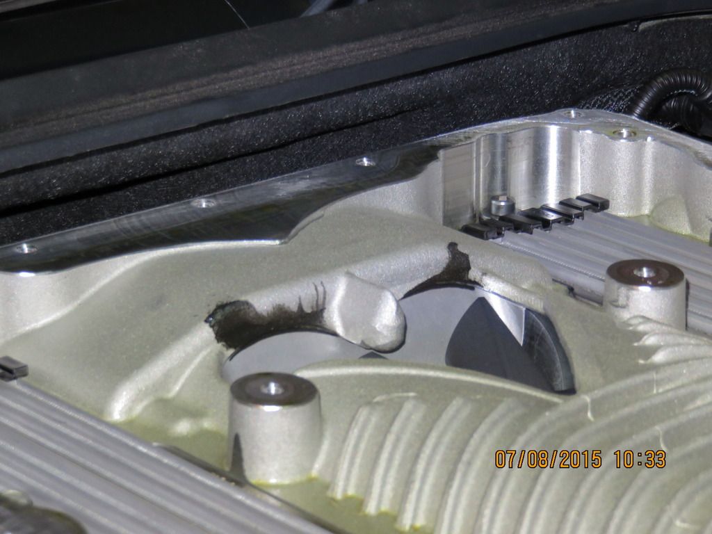
This is a nearly new car and you can already see where the greatest baked on oil is already accumulating.
Also, the LT4 has a newly designed cleanside cyclonic oil separator that seems to be doing an excellent job on the cleanside, so the Elite cleanside unit is NOT needed, just the dual outlet/dual checkvalve air oil separator system, so that part is less expensive and easier!
So, lets start with removing the top cover of the supercharger housing. The rear most bolts are easier to access if you pull the rubber hood-dust seal off of the plastic surround. All are 10mm so a simple socket and combination wrench will allow this. Set gasket and cover aside and clean all visible oil. Then looking at the boost bypass valve you will see it can be opened and kept this way with anything handy to prop it in the open position. Now would be a good time to remove and clean the throttle body of any existing residue. Brake clean will work fine with a clean rag. Don't miss the cast-in sump depression just inside the snout as oil collects there.
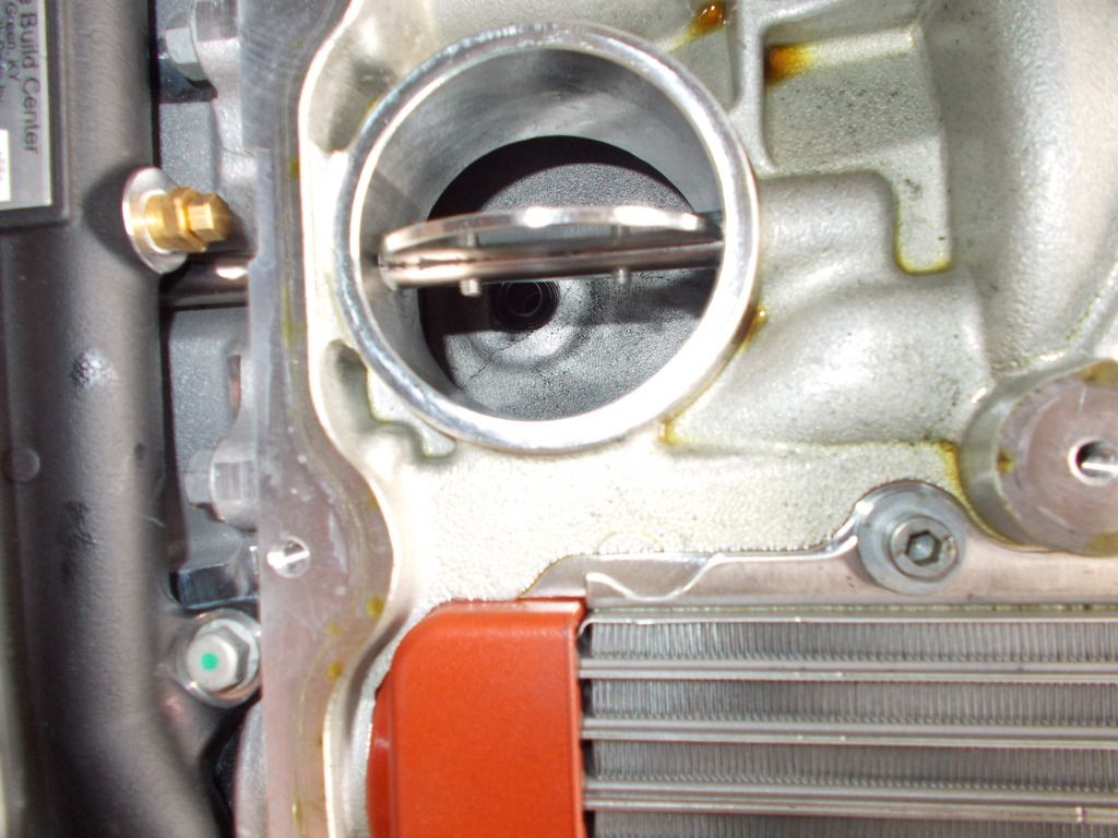
See above with the bypass valve propped open the opening for the tube that comes from the valley is where the foul/dirty side vapors vent directly into the inlet plenum of the SC. This needs to be plugged, and this must be done so that it cannot pop out, so we designed a tapered soft Delrin plug that can be tapped firmly into place. First use RTV or Permatex �Right Stuff to fill in a good part of the vent tube that is being plugged and then coat bottom of plug as well to ensure a good seal. Let cure for 2 hours minimum for Right Stuff and 6-12 hours for RTV. So with a light hammer, a flat end punch, and a section of wooden dowel or similar that you can super glue the plug onto to place it in the PCV tube end and tap home and secure. Check with needle nose pliers to ensure it is secure :
Once this has been completed re-install the upper plenum and we will now move to the easy part of the install!
 09-01-2015, 04:11 PM
#22
Melting Slicks
Thread Starter
We are not going to be changing anything on the dry-sump tank or the lines on the passenger side of the engine except removing the hard black plastic line that stock runs to the front of the drivers side valve cover. Make sure to run a line from the the end near the dry-sump tank that you removed the hard line that ran from the drivers side valve cover front to �T� into one of the remaining hard lines that attach to the passenger side so no lines are left open as shown below:
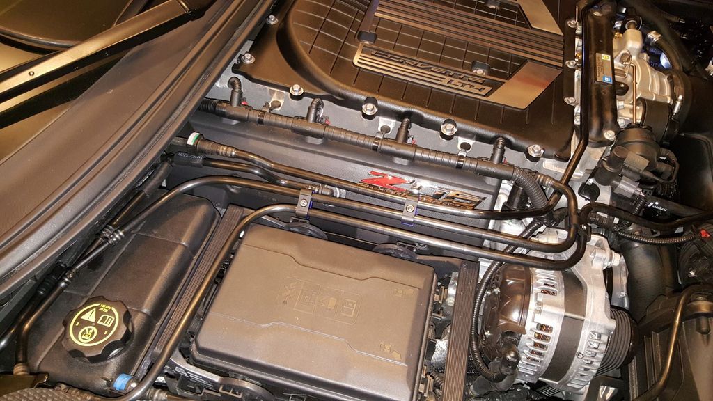
You will mount the separating unit as shown below, make sure to tighten all bolts well, but do NOT over tighten and break any!
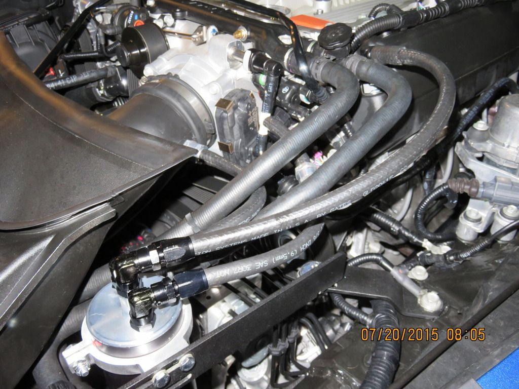
Note, coat the end of a 3/8� drill bit in grease to capture any debris from drilling, and drill a hole where shown, and then inset the 14/NPT x 3/8� barb as shown. This will be where the second outlet with inline checkvalve flowing away from the can connects for additional evacuation suction when in boost. The primary outlet from can (outer fitting) w/chk valve flowing away from can (valves have directional arrows) will connect to a �T� that you cut the vacuum line that feeds the brake booster and insert here. This provides the primary suction needed for evacuation. The provided T will fit into the inside of the line where you cut it. Warming the tube with a hairdryer or heat gun will soften the hard plastic so it can fit inside more easily.
The center of the can with NO valve inline connects to the fitting on the front of the drivers side valve cover (included) and that is it for routing.
The clamp on the can can be supported by the O-ring included until you have positioned it where you want it before tightening it and securing the clamp.
09-01-2015, 04:13 PM
#23
Melting Slicks
Thread Starter
Will leave this as is as it has a ton of pictures, but this should give anyone that is interested in the systems what is involved.
This is for both the Elite Engineering and the Colorado Speed systems.

Ask more questions. There is no such thing as a "dumb" question if you are not totally clear with all involved.
This is for both the Elite Engineering and the Colorado Speed systems.
Ask more questions. There is no such thing as a "dumb" question if you are not totally clear with all involved.
09-01-2015, 04:20 PM
#24

Would you consider this problem excessive? Shoddy or lazy design from GM? Corner-cutting?
Do you think that adding this catch-can would cause warranty issues down the road, or be seen as a "****ing duh!" addition that should be on every car and help save GM from paying for warranty work?
Do you think that adding this catch-can would cause warranty issues down the road, or be seen as a "****ing duh!" addition that should be on every car and help save GM from paying for warranty work?
09-02-2015, 12:11 PM
#25
Melting Slicks
Thread Starter
Would you consider this problem excessive? Shoddy or lazy design from GM? Corner-cutting?
Do you think that adding this catch-can would cause warranty issues down the road, or be seen as a "****ing duh!" addition that should be on every car and help save GM from paying for warranty work?
Do you think that adding this catch-can would cause warranty issues down the road, or be seen as a "****ing duh!" addition that should be on every car and help save GM from paying for warranty work?
Keep the questions coming. My goal is for all to understand all there is to know about the unique issues and care for GDI engines.
09-03-2015, 06:09 PM
#26
Melting Slicks
Thread Starter
I have revised our first thread to show pictures of the coloradoSPEED oil catch and clean side air/oil separator. Once I have pictures of the new revised Elite Engineering catch can, I will add that. Thanks.

 09-04-2015, 01:26 PM
#29
Melting Slicks
Thread Starter
Went over all of this in detail, in the US a system like those I recommend by law, it cannot. Now if you do one that deletes and defeats the PCV systems functions absolutely yes it will as that will lead to engine damage over time.
09-06-2015, 01:16 AM
#30

coSpeed2
I noticed this LMR forced induction catch can had breathers on it and Colorado Speed and E2-X catch can do not. Breathers just required for ventilation?
https://weaponx-c7.myshopify.com/col...-catch-can-kit
I noticed this LMR forced induction catch can had breathers on it and Colorado Speed and E2-X catch can do not. Breathers just required for ventilation?
https://weaponx-c7.myshopify.com/col...-catch-can-kit
Last edited by LiftHeavy; 09-07-2015 at 02:04 PM.
09-07-2015, 11:35 PM
#31

First of all - thanks to coSPEED2. I realize you're working for a vendor, but you have taken the time to give good technical explanations, which is how I would expect someone with the best system to respond.
I have a Z07 on order and would like to do this mod first thing to avoid any coking/buildup from the beginning.
You shared a good explanation on why the LT4 doesn't need the clean side separator - but it only makes me want to better understand the plumbing of the stock system and how that is changed with your catch can. If I understand, the tube that we have to plug beneath the bypass butterfly leads down to the crankcase. After plugging it, where are we relying on the crankcase pressure to flow through?
A diagram would be worth a thousand words here if you have anything.
09-08-2015, 01:08 PM
#32
Melting Slicks
Thread Starter
coSpeed2
I noticed this LMR forced induction catch can had breathers on it and Colorado Speed and E2-X catch can do not. Breathers just required for ventilation?
https://weaponx-c7.myshopify.com/col...-catch-can-kit
I noticed this LMR forced induction catch can had breathers on it and Colorado Speed and E2-X catch can do not. Breathers just required for ventilation?
https://weaponx-c7.myshopify.com/col...-catch-can-kit
The PCV system performs many functions and emissions is only one of them. These damaging compounds that are entering via blow-by must be removed (flushed and evacuated by suction/vacuum out) while still suspended or they quickly settle and accumulate in the oil. A simple oil analysis from any engine running such a system will show the concentrations of these contaminants. So no, these take the critical "Fresh" side and "foul" sides and run them both into one tank so they only relieve pressure AFTER it has first built, and this causes damage to the piston rings from "ring flutter". You always want to have constant steady evacuation and flushing of fresh air entering one side or portion of the crankcase, and foul damaging compound laden vapors sucked out the opposite. This constant "flushing and removal" of these damaging compounds is critical for long engine life.
First of all - thanks to coSPEED2. I realize you're working for a vendor, but you have taken the time to give good technical explanations, which is how I would expect someone with the best system to respond.
I have a Z07 on order and would like to do this mod first thing to avoid any coking/buildup from the beginning.
You shared a good explanation on why the LT4 doesn't need the clean side separator - but it only makes me want to better understand the plumbing of the stock system and how that is changed with your catch can. If I understand, the tube that we have to plug beneath the bypass butterfly leads down to the crankcase. After plugging it, where are we relying on the crankcase pressure to flow through?
A diagram would be worth a thousand words here if you have anything.
I have a Z07 on order and would like to do this mod first thing to avoid any coking/buildup from the beginning.
You shared a good explanation on why the LT4 doesn't need the clean side separator - but it only makes me want to better understand the plumbing of the stock system and how that is changed with your catch can. If I understand, the tube that we have to plug beneath the bypass butterfly leads down to the crankcase. After plugging it, where are we relying on the crankcase pressure to flow through?
A diagram would be worth a thousand words here if you have anything.
Fresh filtered MAF metered air enters the dry sump oil tank from the main intake air bridge. It then splits and travels to both valve covers (drivers side shown here where you can see the barb at the front top of it):

where it is drawn from the intake air charge vacuum past both banks valvetrain components (all the time flushing and carrying with it the damaging compounds that enter as blow-by) down the push rod and oil return galley's, into the main portion of the crankcase where they are drawn up the center through a baffle located unto the valley cover (center cover under the super charger) as shown here:

There is a tube that comes from the top of that baffle and enters the bottom of the SC housing into the intake side of the blower. This is where the oil laden vapors enter to be burned in the combustion chamber and further in the catalytic converters. The problem is with GDI there is no fuel spraying on the intake valves like with past port injection engines to keep them cool and clean, so now all of this bakes onto the backsides of the valves causing these issues. So you do not want to delete the functions of the PCV system, simply separate and trap these compounds before they can make contact.
What we do is plug the tube, and then utilize the drivers side valve cover front for evacuation as the L99 engines do. Same cross flow flushing, same evacuation, just changing where it enters and exits. This eliminates the "hidden" entry point and allows for the installation of a air/oil separating system.
I want to also add, the Elite E2 is a great choice for a port injection engine, but will not be effective enough to prevent the coking. You will want the just released E2-X separator or the "Ultra" for race applications.
Also, as the top mount SC of the LT4 provides suction at all throttle positions (unlike a NA engine that does not when under acceleration) so the cleanside is only recommended for those racing or running hard often. It then replaces the oil fill cap and then the front most hard line from the main air bridge unsnaps and snaps onto the cleanside separator (no cutting that line) and then you cap the open barb on the tank.
Good questions all!!
09-08-2015, 01:35 PM
#33
Instructor

I assume that the only difference between the Elite E2-X and the Colorado Speed version is aesthetics since you are promoting them both. Does Colorado sped have license from elite to use their engineering. Also I notice that elite does not have the option for braided lines. Is this just an oversight or something colorado speed is solely doing. I assume no harm adding the clean side on the LT4 just in case the driving is spirited. Also is the ultra version in elite(no sure if offered by colorado speed) just a larger can with everything else being equal(ie. Less frequent changes). I took delivery of my Z06 one month ago and I have been holding off driving "too much" until I was able to install this mod. You seem to present overwhelming evidence for the need for such a modification
09-08-2015, 01:40 PM
#34
Burning Brakes

I assume that the only difference between the Elite E2-X and the Colorado Speed version is aesthetics since you are promoting them both. Does Colorado sped have license from elite to use their engineering. Also I notice that elite does not have the option for braided lines. Is this just an oversight or something colorado speed is solely doing. I assume no harm adding the clean side on the LT4 just in case the driving is spirited. Also is the ultra version in elite(no sure if offered by colorado speed) just a larger can with everything else being equal(ie. Less frequent changes). I took delivery of my Z06 one month ago and I have been holding off driving "too much" until I was able to install this mod. You seem to present overwhelming evidence for the need for such a modification
09-08-2015, 02:59 PM
#35
Melting Slicks
Thread Starter
I assume that the only difference between the Elite E2-X and the Colorado Speed version is aesthetics since you are promoting them both. Does Colorado sped have license from elite to use their engineering. Also I notice that elite does not have the option for braided lines. Is this just an oversight or something colorado speed is solely doing. I assume no harm adding the clean side on the LT4 just in case the driving is spirited. Also is the ultra version in elite(no sure if offered by colorado speed) just a larger can with everything else being equal(ie. Less frequent changes). I took delivery of my Z06 one month ago and I have been holding off driving "too much" until I was able to install this mod. You seem to present overwhelming evidence for the need for such a modification
I promote both as both I have seen work in person so know the results (many A-B and then reversed B-A test's). Elite does all of their cans in a billet style. The cleansides you are also correct, no harm at all, I just have not seen much of any cleanside ingestion on the LT4 so as I am not in sales, I will always not urge any to spend $ they don't need to.
But for those that do track and run extended high RPM/heavy throttle it is an added feature to ensure no ingestion.
On braided lines, I am not sure on the Elite, but I think they will as they do with their other cans. Will have to confirm w/Elite on that though.
The "Ultra" everything is larger, internal coalescing chamber, condensing and collection chambers, outlet chamber, etc. so it is the true "Ultimate" as described. The best in air/oil separation and added capacity.
This is a definite issue and this is why I urge any that doubt it if they have a LT1 (hard to remove LT4 SC to see) to take a few minutes and remove their intake manifold and inspect their own valves. Then it is right there for them to see.
Yes, BUSA was a first beta tester I believe for the system so he is a good example.
09-08-2015, 03:13 PM
#36
Le Mans Master


toyota & subie attacked this problem by having another standard port injector in addition to the GDI so there is still fuel flow and valve contaminate washed off by the fuel.
not really an ez option and yes GM spend a pretty penny looking at issues with Audi and BMW that seemed prone to valve deposits.
from what I have read on the topic, the GM engines such as the GDI ecotech 4 for some reason aren't as prone to this same issue and it's clearly a result of "improved oil vapor" management within these engines.
has anyone with a c7 gotten over 50k miles and pulled the intake to see what the valves look like?
as an interim solution some fogging of a high detergent cleaner "down the throat" with the engine running every now and then might help a bit.
as does punching it often so the oil vapors aren't flowing so slowly giving them less chance to bind. good oil changed frequently I would think would help as well.
very good article pointing out some of the down sides to GDI
it's a much more complex but efficient fuel delivery system, but not so kind to the valves.
09-08-2015, 04:07 PM
#37
Melting Slicks
Thread Starter
toyota & subie attacked this problem by having another standard port injector in addition to the GDI so there is still fuel flow and valve contaminate washed off by the fuel.
not really an ez option and yes GM spend a pretty penny looking at issues with Audi and BMW that seemed prone to valve deposits.
from what I have read on the topic, the GM engines such as the GDI ecotech 4 for some reason aren't as prone to this same issue and it's clearly a result of "improved oil vapor" management within these engines.
has anyone with a c7 gotten over 50k miles and pulled the intake to see what the valves look like?
as an interim solution some fogging of a high detergent cleaner "down the throat" with the engine running every now and then might help a bit.
as does punching it often so the oil vapors aren't flowing so slowly giving them less chance to bind. good oil changed frequently I would think would help as well.
very good article pointing out some of the down sides to GDI
it's a much more complex but efficient fuel delivery system, but not so kind to the valves.
not really an ez option and yes GM spend a pretty penny looking at issues with Audi and BMW that seemed prone to valve deposits.
from what I have read on the topic, the GM engines such as the GDI ecotech 4 for some reason aren't as prone to this same issue and it's clearly a result of "improved oil vapor" management within these engines.
has anyone with a c7 gotten over 50k miles and pulled the intake to see what the valves look like?
as an interim solution some fogging of a high detergent cleaner "down the throat" with the engine running every now and then might help a bit.
as does punching it often so the oil vapors aren't flowing so slowly giving them less chance to bind. good oil changed frequently I would think would help as well.
very good article pointing out some of the down sides to GDI
it's a much more complex but efficient fuel delivery system, but not so kind to the valves.
Good post. I covered the small port injectors added by Audi and others in an attempt to slow the coking, but so far it has had nominal effect at slowing the coking, but had a downside and that is a higher incidence of detonation and knock retard as these all are 11.3-11.5:1 CAR as GDI eliminates much of the detonation by having no fuel present during the intake and most of the compression stroke, allowing them to run such hi CR's. When they added the small port injectors to "improve off idle throttle response" (as they had claimed they had no issue with coking LOL) this then introduced fuel in the intake and compression stroke and detonation came back. So no, that has not had much benefit, and the negative out-weighed the small improvement it gave. You can also find each automaker has patented fueling event's to try and spray a bit early into the combustion chamber so that when the valves were still open some fuel could make contact, but again in practice no real reduction in coking and an increase in detonation.
GM is one of the worst offenders, as anyone taking the intake manifold off any of the current or past generations of GDI can see personally so their PR claim is not accurate in that regard. ALL auto makers have made great strides in "vapor control", but at 20% separation effectiveness is where the downside of also retaining the damaging compounds that cause premature engine wear and damage come into play so they cannot go further as there is far more than oil alone in the mix that causes the coking.
A good full synthetic oil does help as it leaves less deposits than a blend or straight conventional, but that is also having minimal effect when you inspect these engines in person. So until there is an effective way to separate these compounds from the intake air charge and still retain the critical functions of evacuation, this is not a problem that any automaker has a handle on (yet all claim they have no issue now).
Here are some pictures (have posted them before, but here they are to refresh)
Below, new GDI w/app 20k miles on it:

Average modern (newer) GDI valve at 40-50k miles (watch when we get some 2014 and newer GM V8 GDI's apart to see at this mileage and compare):

And below is why using a solvent based upper induction cleaning is bad for GDI where it was fine for older port injection engines:

The wear to the valve guides by pulling these hard abrasive deposits up in every cycle will still occur, and since these deposits are baked so hard and crystallized the damage that occurs to the pistons and cylinder walls from these hard particles breaking loose is substantial, so that is not recommended (except by the companies selling them!). In the past the port injection carbon build up was a soft easy to remove with these processes and damage was rare, now with GDI it occurs with every cleaning, so this is not a solution, and at best they only loosen app. 50% of the deposits. Best is a crushed walnut shell manual procedure. This cleans it all w/no damage if performed properly, but that does not prevent the deposits from reforming. Only stopping the compounds from entering will, and until there is a self emptying solution for the OEM, we all have to empty these at least every oil change or sooner (all engines are different in the amount depending on ring seating).
So, great post, and every automaker claims they have no issues, and the Seafoams, BG's, CRC's, etc. all are jumping on using their solvent based cleaners but the techs tearing these engines down can attest to the damage those cause.
Also, for those considering, or already running a breathered tank system, the damage your causing to the rest of the engine by not evacuating the combustion byproducts and allowing pressure to first built and then vent instead of pulling suction are also causing ring flutter and the damage it causes as outlined in this article:
A phenomenon rarely heard of these days, is that of ring flutter. Manifesting itself in the form of unusual wear characteristics and possibly high exhaust gas blow-by, particularly at light load conditions, ring flutter if left unchecked, can even cause pre-ignition/detonation of the incoming fuel-air charge, eventually leading to piston failure. The solution however, is not always that obvious.
You may always hear that the root of the problem is all to do with the acceleration and deceleration of the piston and is therefore a phenomenon much more likely to happen at high engine speeds. That isn't always the case. If the conditions are right, ring flutter can occur at any speed and is therefore considered now to be more of a dynamic condition as a result of the piston ring moving up and down in the ring groove, twisting as it goes, as well as moving in and out and losing contact with the cylinder wall.
To understand the phenomenon even in part, we need to look at the forces acting on the top ring of the piston. These are the combustion pressure forcing the ring down and the crankcase pressure underneath, counterbalancing it to a limited extent. This ring will also have a slight clearance in the retaining groove in the piston and to assist sealing, a tangential force acting on the cylinder wall. When the engine is operating at full load, the combustion gas will flow between the top of the piston ring and the ring itself and from behind the ring, forcing it outwards. A gas tight seal will therefore result as the ring is seated against the lower face of the piston groove and forced against the cylinder wall.
However under the conditions of flutter when lightly loaded, as the piston slows down, the ring may wish to twist or move and part company with the lower groove face, cutting off the flow of gas to its rear. The ring will then effectively collapse inward, perhaps even breaking contact with the wall and the gas pressure eventually overcoming its now impaired ability to seal, finding its way down towards the crankcase. Passing either side of the piston ring, pressure may build up between the top and second ring grooves, which will then further upset the top ring at certain stages in the cycle and if it hasn't already done so, lift it momentarily off the bore thus making matters even worse. Sometimes accompanied by high oil consumption, the motion is irregular and in a way quite light, like the fluttering of a butterfly. But unlike that (unless you are an advocate of chaos theory) the consequences can be more devastating.
rings-flutter
Lest you forget, the piston ring is a major route for heat transfer between the piston crown and cylinder bore, and eventually into the coolant system and anything that interrupts this flow can have serious consequences to the local temperatures in the piston. During the periods when the ring is not in contact with the surface of the bore, no heat can flow and the piston therefore risks overheating leading to pre-ignition in the combustion chamber.
But rather than just the inertia of the ring in the groove or its design, modern thinking suggests that the phenomenon of ring flutter is more down to the incompatibility between the piston ring and the piston itself, than one factor alone. The design of the ring, barrel or otherwise, if it has a bevel on the inside or not and also the quality of the ring groove in the piston are all issues. Incompatibilities in thermal expansion as well as that in thermal conductivity can both influence the condition and if left uncorrected will steadily destroy the geometry of the area and give the wear characteristics so evidently identifiable as ring flutter.
Keep the good post's coming, this is the way to learn and share misconceptions, etc. and actual experience.
09-09-2015, 11:17 PM
#38
Melting Slicks
Thread Starter
FYI, we NOW have the ELITE E2-X cans up on our site along with our own CS cans.
09-12-2015, 07:51 AM
#39
Team Owner


toyota & subie attacked this problem by having another standard port injector in addition to the GDI so there is still fuel flow and valve contaminate washed off by the fuel.
not really an ez option and yes GM spend a pretty penny looking at issues with Audi and BMW that seemed prone to valve deposits.
from what I have read on the topic, the GM engines such as the GDI ecotech 4 for some reason aren't as prone to this same issue and it's clearly a result of "improved oil vapor" management within these engines.
has anyone with a c7 gotten over 50k miles and pulled the intake to see what the valves look like?
as an interim solution some fogging of a high detergent cleaner "down the throat" with the engine running every now and then might help a bit.
as does punching it often so the oil vapors aren't flowing so slowly giving them less chance to bind. good oil changed frequently I would think would help as well.
very good article pointing out some of the down sides to GDI
it's a much more complex but efficient fuel delivery system, but not so kind to the valves.
not really an ez option and yes GM spend a pretty penny looking at issues with Audi and BMW that seemed prone to valve deposits.
from what I have read on the topic, the GM engines such as the GDI ecotech 4 for some reason aren't as prone to this same issue and it's clearly a result of "improved oil vapor" management within these engines.
has anyone with a c7 gotten over 50k miles and pulled the intake to see what the valves look like?
as an interim solution some fogging of a high detergent cleaner "down the throat" with the engine running every now and then might help a bit.
as does punching it often so the oil vapors aren't flowing so slowly giving them less chance to bind. good oil changed frequently I would think would help as well.
very good article pointing out some of the down sides to GDI
it's a much more complex but efficient fuel delivery system, but not so kind to the valves.
no issue on my example.
09-13-2015, 01:27 PM
#40
Melting Slicks
Thread Starter
We have quite a bit of road racers and general end users who run their cars hard and have said they are having an issue and they either 1. need a catch can or 2. their current catch can is not working.
Last edited by COSPEED; 09-15-2015 at 03:20 PM.