
New Brake Spindle Duct Design
 01-02-2008, 05:14 PM
#1
Heel & Toe

Thread Starter
Member Since: Apr 2005
Location: Circle Pines MN
Posts: 17
Likes: 0
Received 0 Likes
on
0 Posts
Would anyone be interested in better spindle ducts that more effectively channel air directly into the center of the rotor? I was researching them for my own car and wasn't sure I liked what is currently available on the market enough to part with my money. The spindle ducts I've seen appear to have an air feed tube that blows only 1/3 to 1/2 of its potential volume into the center of the rotor and the rest appears to blow on the surface of the rotor.
I've got a cad design and a manufacturer ready to pull the trigger on these, but I thought maybe a little market analysis was a good idea before spending the $1000's to make this happen. These spindle ducts would force the air only into the very center of the rotor, with no spillage, via two slightly smaller inlets (one in the top 1/4 of the rotor, one in the bottom 1/4 of the rotor). I would have to sell them for around $150 to $200 per pair (same as those that are currently available). I'm also tossing around the idea of having a lip formed into the spindle duct that would fit within the inside of the rotor to further direct air into the rotor.
For it to be cost effective to manufacture I would need to sell quite a few of them. Unfortunately, tooling isn't cheap on this.
These would be very high quality pieces, laser cut, and professionally welded, with tight tolerances. Currently, my design is for the C5, but would likely be easy to modify to work on the C6 (if modifications are even necessary). What do you all think? Is there at least the size market I need to make it worth doing?
Thank you for your input...
 01-02-2008, 05:20 PM
#2
Team Owner


hard to say without seeing the design but I know you don't want to release it. I don't know if we are only getting 1/2 in the present design now, How do the air supply tube hook up to yours? How does it get to the center with the bearing there?
01-02-2008, 05:32 PM
#3
Team Owner
hard to say without seeing the design but I know you don't want to release it. I don't know if we are only getting 1/2 in the present design now, How does the air supply tube/tubes hook up to yours?
01-02-2008, 05:40 PM
#4
Heel & Toe
Thread Starter
Member Since: Apr 2005
Location: Circle Pines MN
Posts: 17
Likes: 0
Received 0 Likes
on
0 Posts
I'd be using 2 slightly smaller sort of oval shaped inlets; both where the current spindle duct blows and just below the forward pointing arm of the knuckle. Two flexible hoses would attach to it. Those would be joined with a small lightweight "Y" to connect with a single 3" tube near the back of the wheel well.
I figure that the two combined inlets should be able to send a fair amount more air through the rotor.
Are you aware of any spindle ducts currently available for the C6's or if the interior dimension of the C6 rotor is the same as the C5? I haven't researched them yet.
I figure that the two combined inlets should be able to send a fair amount more air through the rotor.
Are you aware of any spindle ducts currently available for the C6's or if the interior dimension of the C6 rotor is the same as the C5? I haven't researched them yet.
01-02-2008, 05:45 PM
#5
Team Owner
I am sure LGM makes a C6 it may be the same not sure others will chime in here I'm sure on C6. Is the area of the two small tubes bigger? Then you need the y piece to the supply. How are the two hoses going to hold up when the wheel turns the way you route them? The current spindle duct is dumping into a vacuum so I don't know how much is lost?
01-02-2008, 07:24 PM
#6
Safety Car

On my C5 w/ BAER rotors I had to do alot of trimming on the spindle ducts. I don't know if that's required on stock rotors... just thought I'd mention they aren't all the same.
Arnel
Arnel
01-02-2008, 07:55 PM
#7
Premium Supporting Vendor
Member Since: Oct 2001
Location: Dallas Tx
Posts: 8,392
Received 571 Likes
on
292 Posts
St. Jude Vendor Donor '03-'04-'05-'06-'07-'08-'09-'10-'11


Hi guys,
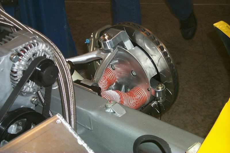
Here is what we use on our Race car (photo from race car) and our street spindle ducts and I can tell you that it is much more than any track day car will need.
It worked on our Race Cars with no issues and we used our brakes harder than most all DE Track cars.
Having said that, we would have done more if we needed to. Racing will bring out the weakest link in any system, and our brakes had no issues.
thanks And good luck with your spindle duct design.
Lou Gigliotti
LGM
__________________
LG Pro LT Headers, MOST HP, MOST TORQUE
http://lgmotorsports.com/gallery/alb...no_compare.jpg


LGM http://www.LGMotorsports.com
Winner Daytona 250
22 WC Wins
"Most powerful Corvette headers on the planet"

LG Pro LT Headers, MOST HP, MOST TORQUE
http://lgmotorsports.com/gallery/alb...no_compare.jpg
LGM http://www.LGMotorsports.com
Winner Daytona 250
22 WC Wins
"Most powerful Corvette headers on the planet"
01-02-2008, 10:45 PM
#8

^^^
don't waste your time reinventing the wheel. There is nothing to gain. If anything, too much air get to the center of the rotor in current designs, causing massive air shock and contraction of the rotors, also causing cracking.
don't waste your time reinventing the wheel. There is nothing to gain. If anything, too much air get to the center of the rotor in current designs, causing massive air shock and contraction of the rotors, also causing cracking.
01-03-2008, 04:04 AM
#9
Heel & Toe
Thread Starter
Member Since: Apr 2005
Location: Circle Pines MN
Posts: 17
Likes: 0
Received 0 Likes
on
0 Posts
I am sure LGM makes a C6 it may be the same not sure others will chime in here I'm sure on C6. Is the area of the two small tubes bigger? Then you need the y piece to the supply. How are the two hoses going to hold up when the wheel turns the way you route them? The current spindle duct is dumping into a vacuum so I don't know how much is lost?
I would expect to route both inlet tubes rather similarily to the current 3" option so I'm hoping the routing would work.
01-03-2008, 04:48 AM
#10
Team Owner
I honestly don't know how much is lost either. Without a camera and some smoke it would probably be difficult to know for sure. The combined size of the two tubes would be pretty close to a single 3" tube.
I would expect to route both inlet tubes rather similarily to the current 3" option so I'm hoping the routing would work.
I would expect to route both inlet tubes rather similarily to the current 3" option so I'm hoping the routing would work.
01-03-2008, 04:49 AM
#11
Heel & Toe
Thread Starter
Member Since: Apr 2005
Location: Circle Pines MN
Posts: 17
Likes: 0
Received 0 Likes
on
0 Posts
http://www.seinesystems.com/MPC-Install.htm#
and an excerpt by Fred Puhn on it.
http://www.seinesystems.com/FPuhnBookQuote.htm
By the way, I appreciate everyones input on this (pro or con). As an FYI to others that have manufactured spindle ducts out there... I really am not trying to offend any of you and say your product is bad. I am merely looking at a potential improvement and trying to get people's opinions on if it's a good or bad idea.
 It does get expensive to manufacture the ducts in different designs similar to the way I have described them and that is why I presumed they were done as they were. I'm pretty confident that if I were to make these I would surely have a smaller profit margin than my competition if I sold them at the same price. The only reason I say it appears that all the available spindle duct models out there feed a large portion of air directly onto the rotors surface is because I have yet to see a picture of one for sale that does not look as though this is the case. If there is one that does not appear to do this please post a few definitive pictures and tell me who sells it.
01-03-2008, 04:56 AM
It does get expensive to manufacture the ducts in different designs similar to the way I have described them and that is why I presumed they were done as they were. I'm pretty confident that if I were to make these I would surely have a smaller profit margin than my competition if I sold them at the same price. The only reason I say it appears that all the available spindle duct models out there feed a large portion of air directly onto the rotors surface is because I have yet to see a picture of one for sale that does not look as though this is the case. If there is one that does not appear to do this please post a few definitive pictures and tell me who sells it.
01-03-2008, 04:56 AM
#12
Team Owner
you have a picture above it goes into the rotor. We have seen the water injection before. Don't know of any pro race teams running it.
01-03-2008, 05:21 AM
#13
Heel & Toe
Thread Starter
Member Since: Apr 2005
Location: Circle Pines MN
Posts: 17
Likes: 0
Received 0 Likes
on
0 Posts
Does anyone have a picture of it installed with a rotor on it looking in from the inlet hole into the rotor?
Here's the link:
http://www.ecsracing.com/ecsracing/s...=1573#post1573
01-03-2008, 07:39 AM
#14
Le Mans Master

Member Since: Feb 2000
Location: Bedford NH
Posts: 5,708
Likes: 0
Received 1 Like
on
1 Post
Cruise-In II Veteran

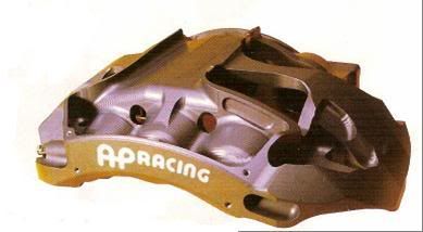
If you want to improve on the current offerings, what is needed is to get some air to the outside face of the rotor. What cracks rotors is not the heating, not the cooling, but the temperature differences (gradients) through the rotor. All of the current designs duct air to the center and inside face of the rotor, leaving the outside face hotter in use than the inside vane area and the inside rotor face. When this happens, the hotter iron outer surface expands more than the cooler inside and goes into tension and since iron is very weak in tension (like concrete, good in compression, but not in tension), it cracks. We are now seeing the new AP calipers ducting air over the top of the rotor and directing it to the outside face. If you figure out a good way to do this, you will really have something unique and marketable. Just my $.02....
01-03-2008, 08:08 AM
#15
Team Owner
Member Since: Sep 2003
Location: Raleigh / Rolesville NC
Posts: 43,084
Likes: 0
Received 25 Likes
on
25 Posts
There are also the Genesis Technologies Carbon Fiber Spindle Brake Ducts: $139.20 each


http://www.hrpworld.com/index.cfm?fo...action=product
http://www.hrpworld.com/index.cfm?fo...action=product
Last edited by AU N EGL; 01-03-2008 at 08:11 AM.
01-03-2008, 10:35 AM
#16
chrisjw:
It is speculation and theory as to what causes rotors to crack, quick cooling/heating cycles or not enough cooling. Personally, every one of my half dozen or so cracked rotors has happened 30 minutes or so after a session, while sittin in the paddock, letting the car cool down.
ghoffman:
It is true that heat gradient between the two surfaces, front and back causes cracking, but that isn't because the outside or 'front' surface doesn't receive enough air, as the air primarily flows to the inside of the rear and it is 'flung' outward through the veins, cooling both surfaces mostly equally. The problem is that the outside surface is cast to the hub mount, not floating, or 'hatted' like superior rotors are.
01-03-2008, 01:47 PM
#17
Le Mans Master
Member Since: Feb 2000
Location: Bedford NH
Posts: 5,708
Likes: 0
Received 1 Like
on
1 Post
Cruise-In II Veteran
I respectfully disagree; the outer surface is much hotter than the cooled interior for an instant when the pads are engaged. It quickly comes to an equilibrium temp, but it is that cycling that causes the cracks. Note the new AP in the pic, it does not have the over the top ducting, but the data shows exactly as I describe happening and that is why it has the air flow as shown.
01-03-2008, 02:45 PM
#18
Former Vendor
Circle Pines MN, That is in our backyard. Are you Turbo Tim's friend??? Do we know you? Do you know us?
Anyways back on track. Why do racers run brake ducts? Well the answer is to keep the pad-rotor within a temp range. To find out the prefect range is alot of testing, the pad manufactor can be a good source for this information also. So do all the Corvettes running around on the track need more cooling then our ducts with any of the spindle ducts out there? Most of them are going to be running on the cold side of the range with that Ours and LGM setup. Which is good to be a little over cool then on the edge of being too hot. It depends on the track-tires-temps and a million other factors. But when I say "most" I should say possible customers in your case.
Gary explained the "cracking" to a tee. I had a big fight with the Midwest AP guy. He deals mostly with short track and oval stuff. Those guys have it easy, hot hot hot hot hot. Us Roadracers on most tracks around here, Hot cold hot hot cold hot hot hot hot hot cold cold. BIR is a pain to get right because of the long straight away, RA is about the same.
Here is a trick setup we did for a WC Car that spends most of the time in FL. He rents the track in the summer and runs the crap out of his cars. We knew the brakes would be baked if we didn't do something. If he came up north more we would suggest a different design like the LGM setup.
01-03-2008, 03:32 PM
#19
Team Owner
Circle Pines MN, That is in our backyard. Are you Turbo Tim's friend??? Do we know you? Do you know us?
Anyways back on track. Why do racers run brake ducts? Well the answer is to keep the pad-rotor within a temp range. To find out the prefect range is alot of testing, the pad manufactor can be a good source for this information also. So do all the Corvettes running around on the track need more cooling then our ducts with any of the spindle ducts out there? Most of them are going to be running on the cold side of the range with that Ours and LGM setup. Which is good to be a little over cool then on the edge of being too hot. It depends on the track-tires-temps and a million other factors. But when I say "most" I should say possible customers in your case.
Gary explained the "cracking" to a tee. I had a big fight with the Midwest AP guy. He deals mostly with short track and oval stuff. Those guys have it easy, hot hot hot hot hot. Us Roadracers on most tracks around here, Hot cold hot hot cold hot hot hot hot hot cold cold. BIR is a pain to get right because of the long straight away, RA is about the same.
Here is a trick setup we did for a WC Car that spends most of the time in FL. He rents the track in the summer and runs the crap out of his cars. We knew the brakes would be baked if we didn't do something. If he came up north more we would suggest a different design like the LGM setup.
Anyways back on track. Why do racers run brake ducts? Well the answer is to keep the pad-rotor within a temp range. To find out the prefect range is alot of testing, the pad manufactor can be a good source for this information also. So do all the Corvettes running around on the track need more cooling then our ducts with any of the spindle ducts out there? Most of them are going to be running on the cold side of the range with that Ours and LGM setup. Which is good to be a little over cool then on the edge of being too hot. It depends on the track-tires-temps and a million other factors. But when I say "most" I should say possible customers in your case.
Gary explained the "cracking" to a tee. I had a big fight with the Midwest AP guy. He deals mostly with short track and oval stuff. Those guys have it easy, hot hot hot hot hot. Us Roadracers on most tracks around here, Hot cold hot hot cold hot hot hot hot hot cold cold. BIR is a pain to get right because of the long straight away, RA is about the same.
Here is a trick setup we did for a WC Car that spends most of the time in FL. He rents the track in the summer and runs the crap out of his cars. We knew the brakes would be baked if we didn't do something. If he came up north more we would suggest a different design like the LGM setup.
01-03-2008, 04:37 PM
#20
Former Vendor
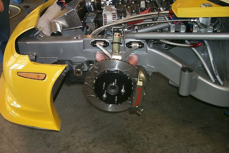
Here is a frame shot. We have been doing this on flat out cars since the early 90's. We are not packaging engineers but it makes sence.
Last edited by Randy@DRM; 01-03-2008 at 04:38 PM. Reason: Sorry picture edit