anyone experience creating a cam sensor for sequential injection?
 08-03-2015, 10:24 PM
#1
Drifting

Thread Starter
Member Since: Dec 2007
Location: Sumter South Carolina
Posts: 1,661
Likes: 0
Received 7 Likes
on
7 Posts

This is a weird one. Please please please stick with the subject at hand. Don't go off into why batch fire is adequate and only sacrificing a few hp. I know you all can do it!
In order to run a sequential injection on my road race engine, I need a crank and cam sensor. The crank will be a wheel on the outside of the dampener and behind the crank pulley. I am tack welding the sensor to the timing chain cover about where the timing pointer is.
The tricky part is the cam sensor. The easiest option is to cut the reluctor trigger down to one tooth. This is something I don't want to do because if I ever decide to sell my Msd unit I can't. ($200 unit). Technically I could go and alter the stock unit but I've had so much trouble with these divorced coil distributors I don't want to take that chance. Another option I can think of would be to weld a gear onto the end of the camshaft gear and cut a hole into the timing cover. However I'm pretty sure there isn't enough room so I would need to cut and extend the cover out to clearance the gear. Seeing how it is right behind the water pump (its late and I'm trying to visualize) it would be tough to accomplish this.
One concern if I cut the teeth off the current trigger, will it cause issues spinning and possibly set a vibration that would kill the distributor housing in a year or so? Or I is small enough it would be insignificant?
This is a 383 stroker with heavy manifold porting that will be used 99% ***** to the wall track days. Solid roller cam and running megasquirt 3 so I can sequential the fuel and have fuel trim tables for each cylinder. No leaning out the rear cylinders like the miniram is famous for. I need the engine to be super reliable. The sequential is purely a safety measure not a "I need more power" thing.


 08-04-2015, 12:28 AM
#3

I have made a cam position sensor with a used distributor,toothed wheel from diyefi and an industrial hall effect sensor.A gutted tpi dizzy would be good because it has no advance mechanism.You can machine an aluminum cover for it-it wont be very tall.You would remove all the teeth except 1-That would tell the ms where the engine is at.The thing about ms is that it doesnt care what you use-it just wants the signal that you set it up for in the software.I ran a car off of an old ms1 a few years back.Very educational.
08-04-2015, 07:59 AM
#4
Le Mans Master

....... Why not use a dual synch distributor like the FAST unit ? ... I am using one with the Holley Dominator ECU to trigger LSx coils and sequential fuel injection on a Gen 1 SBC ..........
08-04-2015, 10:45 AM
#5
Team Owner

Pro Mechanic
Last edited by Tom400CFI; 08-04-2015 at 10:57 AM.
08-04-2015, 11:03 AM
#6
Melting Slicks


What are trying to do is a good idea if it gets you cylinder trim tables. One thing to consider up front is the ECU signal requirements. Min and max voltage mag or hall effect or can it be configured for either. Min and max voltage might still apply though.
08-04-2015, 12:13 PM
#7
Drifting
Thread Starter
Member Since: Dec 2007
Location: Sumter South Carolina
Posts: 1,661
Likes: 0
Received 7 Likes
on
7 Posts
Voltage isnt an issue the ms3 just wants the trigger and can set it to accept pretty much any voltage. I'm in a budget crisis right now so buying a dual sync dis is not economical. I like the vortec look. Might see if I can grab an older one but then again I could just use my other oem distributors. The cover on the 97 sbc is an interesting idea. I'll have to look into if those fit and exist with the cam sensor.
08-04-2015, 12:45 PM
#8
Melting Slicks
What years and applications for that it is a good piece to have available and would buy one new if need be. It is a problem that comes up often in the aftermarket EFI biz and been doing that for over 25 years.
08-04-2015, 07:39 PM
#9
Team Owner
Pro Mechanic
That is from the '96-'99 "Classic" Silverado/GMC Sierra -1/2, 3/4 and 1 tons.
Also, Tahoe, Suburbans...any of the above with either the 305(L30) or the 350 (L31) "Vortec" engine.
Can get 'em from a junk yard all day long for a few dollars (around here).
.
Also, Tahoe, Suburbans...any of the above with either the 305(L30) or the 350 (L31) "Vortec" engine.
Can get 'em from a junk yard all day long for a few dollars (around here).
.
Last edited by Tom400CFI; 08-04-2015 at 07:46 PM.
08-04-2015, 09:52 PM
#11
Team Owner
Pro Mechanic
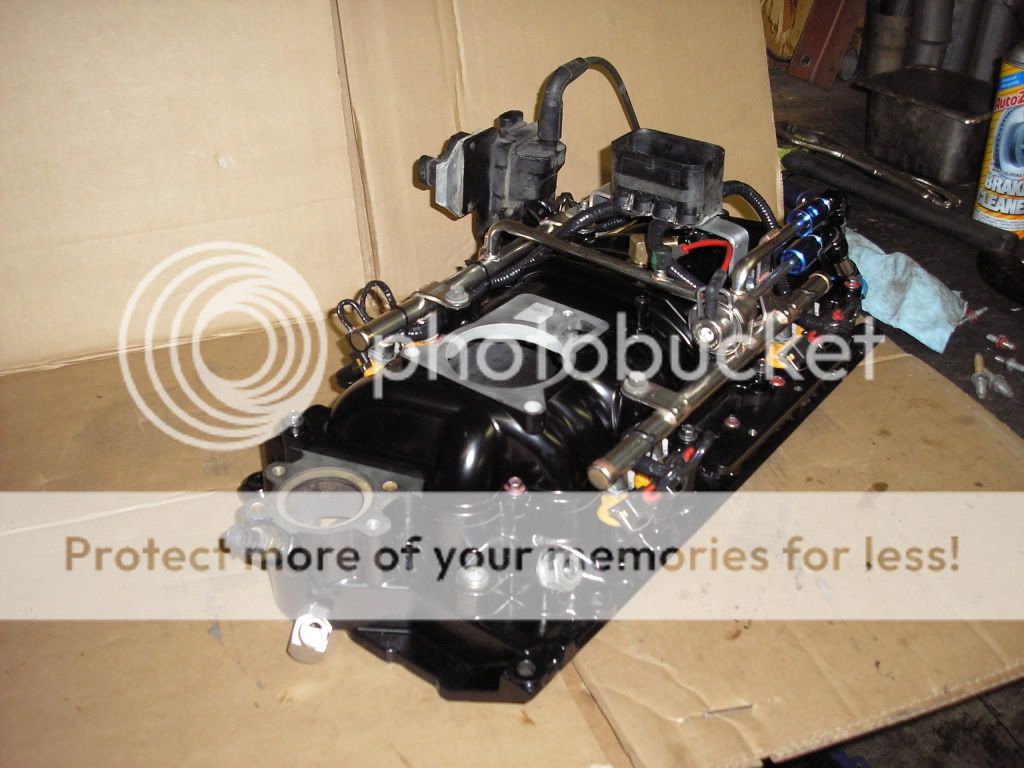
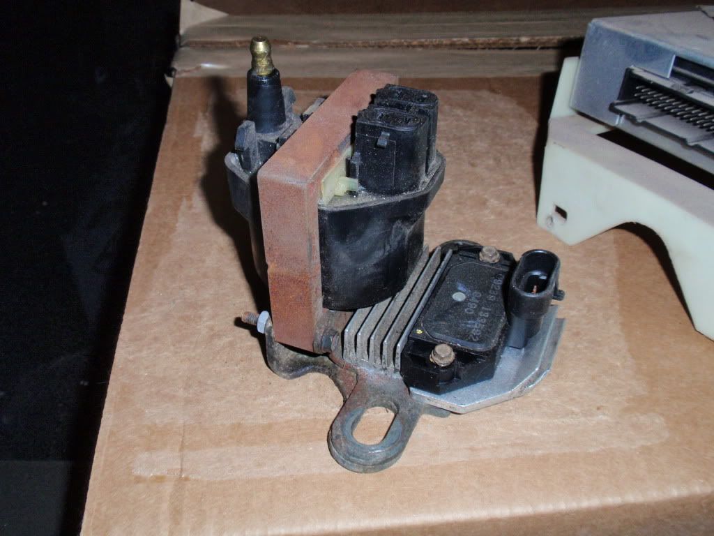
What about it? IDK what your question is, exactly, but the Vortec motor has a remote mounted coil and module, very similar to the coil/module on an LT1 or small cap TPI.
See it in the pic here, mounted on the right, rear of the intake assy...
See it in the pic here, mounted on the right, rear of the intake assy...
08-04-2015, 11:04 PM
#12
Drifting
Thread Starter
Member Since: Dec 2007
Location: Sumter South Carolina
Posts: 1,661
Likes: 0
Received 7 Likes
on
7 Posts
Ahh that was the question. I have a small cap now I converted to. The module is still located inside the cap. I've never seen it anywhere else. Just was thinking of how to heat sync it so it doesn't burn out. Those things get h o t hot. From the picture I still don't see how the distributor "distributes the spark unless it is purely a pickup and ECU sends the spark almost like a coil to cyl system.
08-05-2015, 12:07 AM
#13
Team Owner
Pro Mechanic
Ahh that was the question. I have a small cap now I converted to. The module is still located inside the cap. I've never seen it anywhere else. Just was thinking of how to heat sync it so it doesn't burn out. Those things get h o t hot. From the picture I still don't see how the distributor "distributes the spark unless it is purely a pickup and ECU sends the spark almost like a coil to cyl system.
The Crank sensor is the "now, now, now, now, now, now..." same as your reluctor wheel is currently in your HEI. ECM takes that signal, modifies it for timing advance/retard, and then signals the module to ground the ignition coil and make a spark...same as your car does now. The Cam sensor is for the sequential injection, and the spark is physically distributed by the cap and rotor.
08-05-2015, 12:09 AM
#14
Team Owner
Pro Mechanic
 08-05-2015, 02:08 AM
#15
Melting Slicks
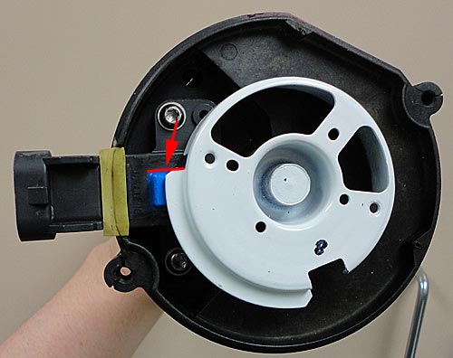
Thanks for the info and would just buy one new if a new system as still a good solution and junkyard shopping around here is hopeless. They have no interest in breaking anything up and then have to clean it up and hope nothing damaged. I am assuming the rotor bolts to the white trigger wheel with the one lobe on it.
08-05-2015, 07:49 AM
#16
Drifting
Thread Starter
Member Since: Dec 2007
Location: Sumter South Carolina
Posts: 1,661
Likes: 0
Received 7 Likes
on
7 Posts
Now if it is a 2x/180* won't it have two triggers? Or do I remove one so I have 1 trigger?
On this system where is the crank trigger? Is it by chance on the outside of the timing chain cover? I could just use the whole system and not buy a custom trigger wheel.
This all looks very promising. Unfortunately the big yard where I live tends to sell Engines as a whole. I think I'll go diving though. If I find one then it can't hurt to try it. If I can't get it to work I always have the slice up option. I like that heat sync and would actually like to have that mount more than anything. That would keep the icm away from the heat of the engine and give me a much nicer mount for my coil than what I have currently.
Wouldn't look too pretty under the hood but would be functional
Last edited by rithsleeper; 08-05-2015 at 07:54 AM.


 08-05-2015, 11:41 AM
#19
Team Owner
Pro Mechanic
You bet! The manifold pictured above is actually a "marine" L31 Vortec intake...the difference being that the fuel rails and injectors are outside the plenum, where in the GM truck, they're inside the plenum. Not relevant to this thread, just mentioning in case someone wondered about the external injectors in that pic.
Rotor is held on by two screws.
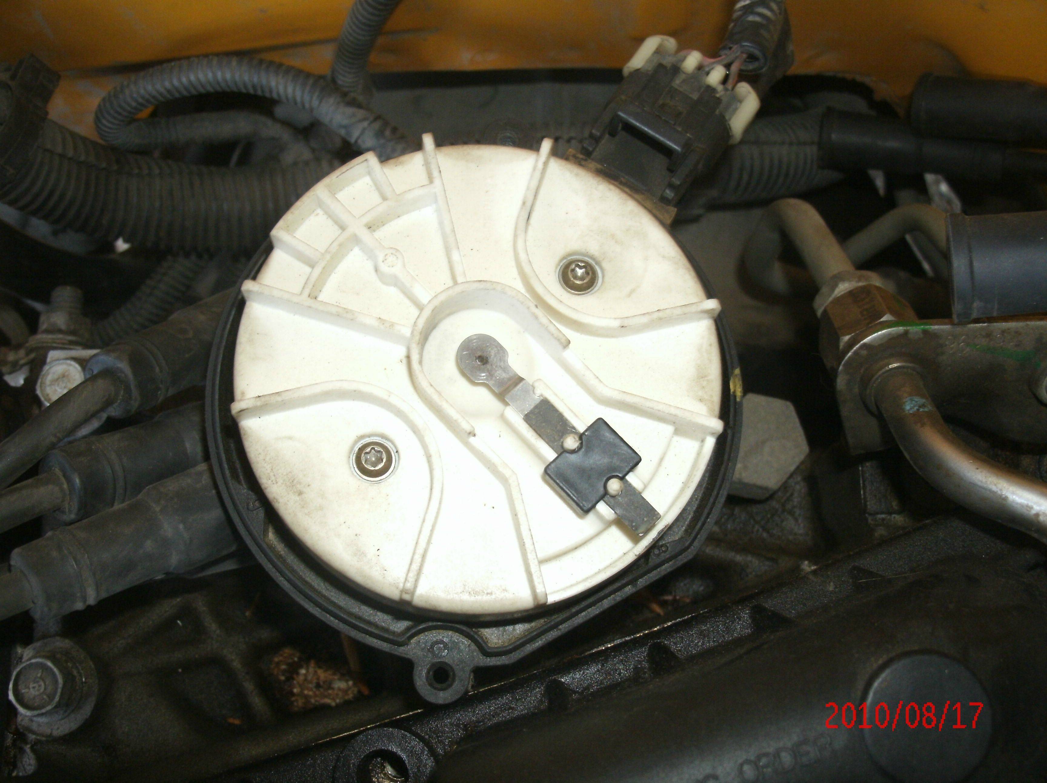
I may not have used the correct term, but there is a signal at (say) 0* when the blade covers the sensor, and then 90* of distributor rotation (180* crank) there is another signal when the blade clears the sensor. IDK if the system uses both signals or not, but they would be there to use.
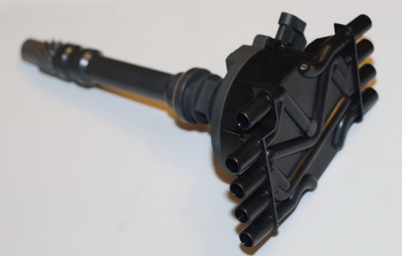
Crank trigger is on the crank, sensor, in the timing cover. Here is a pic of the 4x wheel on the crank...
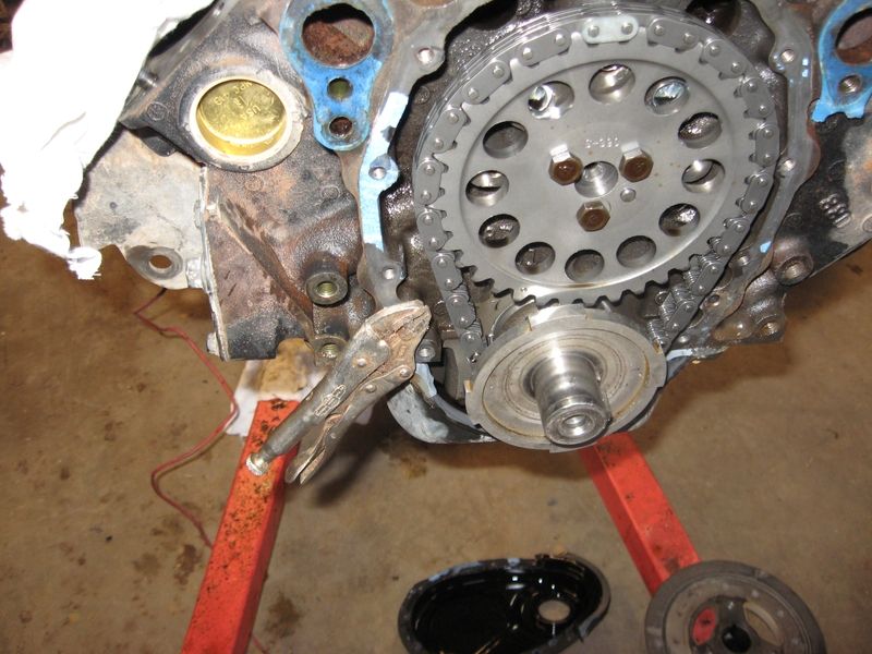
There is a 4x wheel on the crank hub. You could potentially buy/use this whole system. I'd think the aftermarket crank trigger would be more accurate (larger OD and more ref. pulses)? But I don't know for sure. Or would it even matter? Probably not.
You could probably source all the parts off Ebay too.
I have no doubt that you could, but as far as I know, you'd have to also use the L31 ECM. Or some kind of stand alone. I can't see how an LT1 ECM could be adapted to use sensors that provide such a different signal than the opti spark does.
Thanks for the info and would just buy one new if a new system as still a good solution and junkyard shopping around here is hopeless. They have no interest in breaking anything up and then have to clean it up and hope nothing damaged. I am assuming the rotor bolts to the white trigger wheel with the one lobe on it.
Now if it is a 2x/180* won't it have two triggers? Or do I remove one so I have 1 trigger?
On this system where is the crank trigger? Is it by chance on the outside of the timing chain cover? I could just use the whole system and not buy a custom trigger wheel.
This all looks very promising. Unfortunately the big yard where I live tends to sell Engines as a whole. (
On this system where is the crank trigger? Is it by chance on the outside of the timing chain cover? I could just use the whole system and not buy a custom trigger wheel.
This all looks very promising. Unfortunately the big yard where I live tends to sell Engines as a whole. (
Crank trigger is on the crank, sensor, in the timing cover. Here is a pic of the 4x wheel on the crank...
There is a 4x wheel on the crank hub. You could potentially buy/use this whole system. I'd think the aftermarket crank trigger would be more accurate (larger OD and more ref. pulses)? But I don't know for sure. Or would it even matter? Probably not.
You could probably source all the parts off Ebay too.
I have no doubt that you could, but as far as I know, you'd have to also use the L31 ECM. Or some kind of stand alone. I can't see how an LT1 ECM could be adapted to use sensors that provide such a different signal than the opti spark does.
Last edited by Tom400CFI; 08-05-2015 at 11:49 AM.