Proper design and routing for crankcase evacuation
 06-09-2016, 03:21 PM
#1
Melting Slicks

Thread Starter


Wanted to share this from Turbonetics after testing and what they had to say, and the diagrams they provided for proper crankcase evacuation for turbo and Centrifugal SC applications:
"we collect less and less nasty stuff, but the inside of the intake manifold is bone dry. The catch can is working perfectly!
The turbo seems happy as well thus far, meaning we are not pressurizing the crank case under WOT and there is enough suction to keep it that way."
Here are the diagrams:
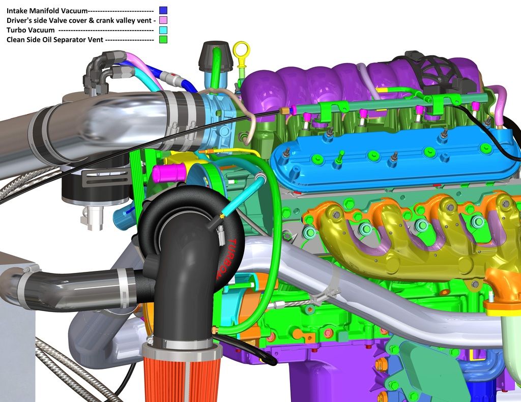
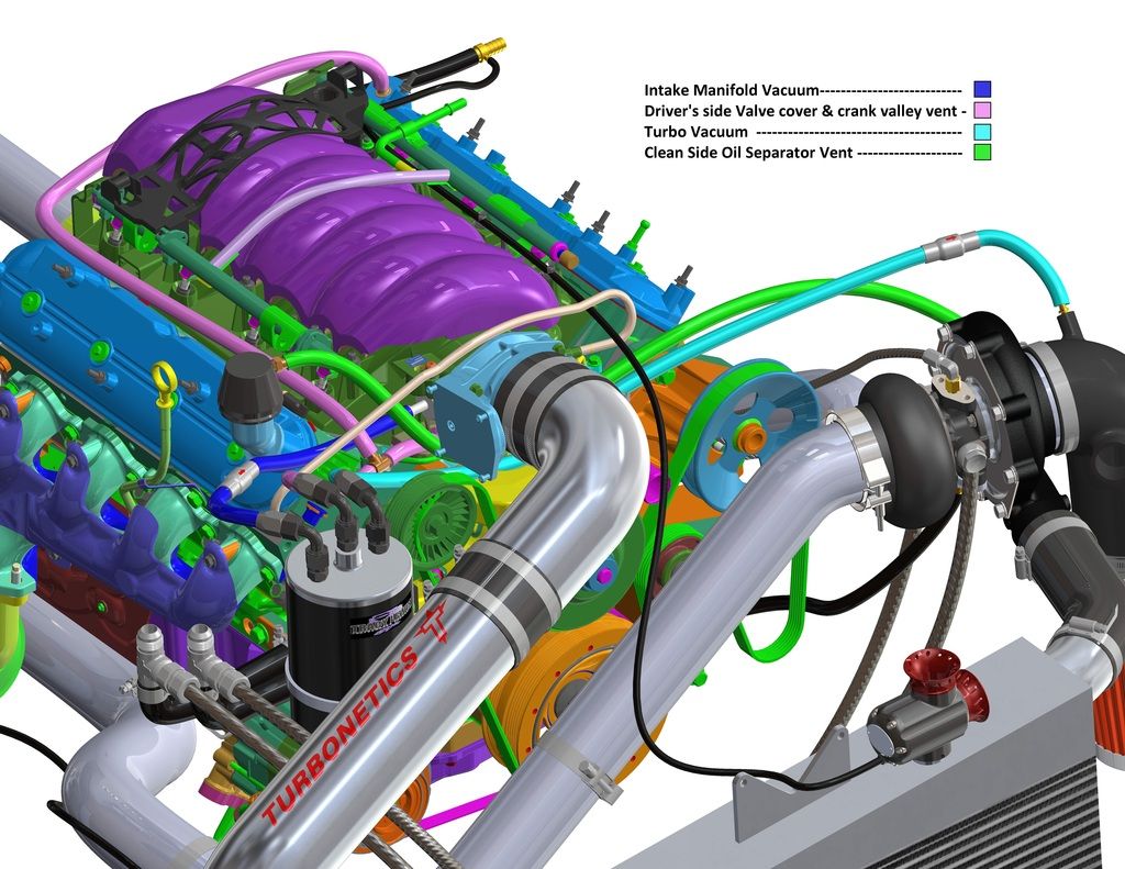
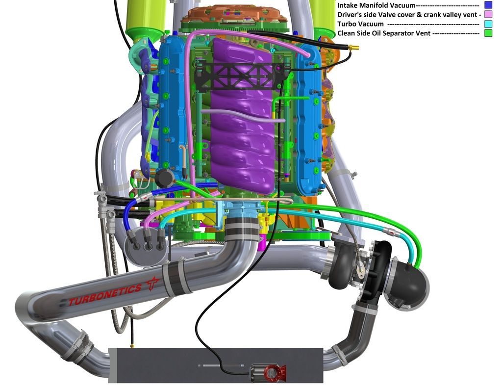
These diagrams apply to the Colorado Speed dual valve, Monster, and the Elite Engineering E2-X and E2-X Ultra systems.
Stops 95% plus of all oil and other contaminants from the intake air charge.
Pulls vacuum/suction on crankcase at all times so never allowing pressure to build. Better ring seal and more power when your not fighting crankcase pressure that a breather or vented system allows.
Less knock retard, and oil stays cleaner longer as the contaminants are constantly removed before they can settle and mix with the oil, etc. A breather or vented system allow most all of these to remain in the crankcase accumulating there.
The next best thing to a belt driven vacuum pump, at a fraction the cost and practical for street use. Also maintains emission compliant closed system.
Questions? Ask any. If you have spent the $ to build your monster, protect that engine properly. Doing this wrong drastically shortens engine life.

"we collect less and less nasty stuff, but the inside of the intake manifold is bone dry. The catch can is working perfectly!
The turbo seems happy as well thus far, meaning we are not pressurizing the crank case under WOT and there is enough suction to keep it that way."
Here are the diagrams:


These diagrams apply to the Colorado Speed dual valve, Monster, and the Elite Engineering E2-X and E2-X Ultra systems.
Stops 95% plus of all oil and other contaminants from the intake air charge.
Pulls vacuum/suction on crankcase at all times so never allowing pressure to build. Better ring seal and more power when your not fighting crankcase pressure that a breather or vented system allows.
Less knock retard, and oil stays cleaner longer as the contaminants are constantly removed before they can settle and mix with the oil, etc. A breather or vented system allow most all of these to remain in the crankcase accumulating there.
The next best thing to a belt driven vacuum pump, at a fraction the cost and practical for street use. Also maintains emission compliant closed system.
Questions? Ask any. If you have spent the $ to build your monster, protect that engine properly. Doing this wrong drastically shortens engine life.
 06-16-2016, 12:41 PM
#2
Melting Slicks
Thread Starter
Anyone dealing with crankcase pressure and related issues please expalin how your doing this, and how it works in detail.
08-10-2016, 03:55 PM
#3
Melting Slicks
Thread Starter
Bumping this up for continued discussions.


 08-11-2016, 11:02 AM
#5
Melting Slicks
Thread Starter
Correct. The only difference is the cleanside is routed through the oil tank. Let us know if you need instructions on that.
08-12-2016, 08:20 AM
#6
So I'd run it right to the oil tank, or would I go from the inlet and tee it to the valve cover and oil tank? Also does it make a difference if the lines are at the turbo/centri inlet or at the outlet? I plan to run a velocity stack on my blower so I can't pull from the inlet.
08-12-2016, 10:48 AM
#8
Melting Slicks
Thread Starter
So I'd run it right to the oil tank, or would I go from the inlet and tee it to the valve cover and oil tank? Also does it make a difference if the lines are at the turbo/centri inlet or at the outlet? I plan to run a velocity stack on my blower so I can't pull from the inlet.
The cleanside will replace the oil fill cap on the dry sump tank, and all entering fresh/clean air will enter through it filtered from the end of the main air filter.
The front most barb on the oil tank used to be the fresh/clean air inlet, so that will then have a line running from it T'd into one of the lines entering the passenger side valve cover. Make SURE you are running valve covers with baffles similar to the stock ones or oil will be slung from the rocker arms up into the outlet on the valve cover on the drivers side (for a LS engine, the LT based GDI have a different configuration).
Amen to that! Just can't get any to live long on the street, but a belt driven vacuum pump is the best possible solution, and then use a adjustable vacuum relief valve on the opposite bank you evac from and try and maintain 14-15" of vacuum at all times on the crankcase.
The following users liked this post:
0FUXGVN (08-12-2016)
08-12-2016, 11:47 PM
#9
Drifting

Thanks for all your recommendations. I've been running my GZ vacuum pump setup for a few yrs now with great results. And all those other routings your showing, I've found work fine to about the 6-700rwhp range give or take depending on how much blow by the motor has. After that I find that they can't keep up under hard or long pulls.
08-13-2016, 07:26 AM
#10
Thanks for all your recommendations. I've been running my GZ vacuum pump setup for a few yrs now with great results. And all those other routings your showing, I've found work fine to about the 6-700rwhp range give or take depending on how much blow by the motor has. After that I find that they can't keep up under hard or long pulls.
Can you please explain your setup? Pics of it?
08-13-2016, 08:22 AM
#11
Drifting
The car is an 07 Z06 with APS manifolds and DP's twin precision 67's the rest is custom fabbed on the car with a 427. PMC intake, Mast Heads, Fore fuel system with a Magna fuel 4303 in line as well. Pro EFI and build drive train from front to back. DP Nitrous as well. No stone unturned lol! The crank case is pretty simple GZ vacuum pump mounted to passenger side head, belt driven to a vented catch can. It has a pressure release valve for adjusting the amount of vacuum. Suction is off of the filler cap on the passenger side valve cover all the other crank case ports are plugged or capped. I'll look but I think most of the pictures are on my PC at home, and I'm at work so they may have to wait til then.
Last edited by inspector12; 08-13-2016 at 08:39 AM.
08-13-2016, 08:55 AM
#12
Race Director

Member Since: May 2004
Location: Raleigh, NC
Posts: 16,664
Received 1,194 Likes
on
1,053 Posts
St. Jude Donor '15

Do you have any kind of crank case fresh air in on a setup like that?
08-13-2016, 10:39 AM
#13
Melting Slicks
Thread Starter
The adjustable vacuum relief valve on the opposite bank (valve cover) as the vacuum pump pulls from will provide the "fresh" or "clean" side of the evacuation system making up for the "foul" or "dirty" vapors being evacuated from the opposite. This gives a full cross flow flushing of the crankcase and there is no better way to not only remove all contaminates form the crankcase before they can settle and mix with the engine oil, but as the vacuum pump has the ability and capacity to pull and maintain far more vacuum than the turbo inlet for a street use system as I posted diagrams for, the vacuum pump will not only provide a better seal for the rings than any other system, it also allows a good deal more power and less wear as the rings maintain optimum stability (no ring flutter). The only short coming is the vacuum pump will need to be rebuilt (not hard) every 5-10k miles from the extended use, and of course it is not emissions compliant as the catch tank has to be vented to allow the amount of flow to release.
This is one guy that understands all of this.
The Monster or Ultra systems I show will work to 1,000 plus HP as long as there are no excessive blow-by issues and -8 or -10 lines are used. The standard sized cans peak at the 600-700 as he states correctly.
Inspector12 apparently understands why evacuation is so critical, and beyond that why you NEVER want pressure allowed to build like a "vented" tank or system does. Pulling evacuation suction at all times is critical as any periods of not evacuating allows the unburnt fuel, water, sulfuric acid, and the particulate contamination to settle and mix with the oil. Once it is in the oil, most is there to stay until you drain and change.
Nice to see someone who truly understands all of this in this discussion! There are so many that do not understand what is involved, and think "venting" pressure is acceptable, and it greatly contributes to engine wear, greater blow-by, and less power.
Here is a good example by Matt Scranton, who we have raced with for years showing the power gains alone VS venting as it seems more and more are doing without understanding the harm it causes over time:
Venting went out 30-40 years ago in all forms of professional racing for these reasons. Even the most budget minded racers that only run local tracks use exhaust header Venturi evac systems if they cannot afford a vacuum pump, but go to any professional race event, from IRL to drag racing, and you only see vacuum pumps on the cars. Look at these carefully, every one has a vacuum pump on it and the next best system for the street are what I keep explaining and endorsing:
08-13-2016, 10:42 AM
#14
Melting Slicks
Thread Starter
I wanted to add, the clean/fresh side inlet valve is adjustable as you do not want to pull more than 14-15" of vacuum on the crankcase or oil begins to be pulled away from the wrist pins, etc. and galling can occur.
inspector12, show pics of what you drain from your tank. It will be mostly water, sulfuric acid, and un burnt fuel showing what otherwise would be staying in the crankcase diluting and contaminating the oil.
inspector12, show pics of what you drain from your tank. It will be mostly water, sulfuric acid, and un burnt fuel showing what otherwise would be staying in the crankcase diluting and contaminating the oil.
08-13-2016, 01:53 PM
#15
Drifting
Its usually about 50-60%water, and then some REAL nasty looking sludge tan in color and I usually have to leave the drain open for a while or spray some brake clean up the drain let it sit for a moment and then drain it. Its a lot easier if I do it after a cruise or basically when its hot, but after a late night I forget or am too lazy at the time etc... Once its cooled off it takes the first method to get the tank completely empty.
08-14-2016, 06:36 PM
#16
Melting Slicks
Thread Starter
When I am back in the office tomorrow, I can give a sample break-down of what is contained in a good evacuation systems catch can. Most is water/acid, then fuel, and then the other abrasive compounds. When you install a "tank" or Breatherd/vented" system, you are defeating the removal of most of this and allowing it to remain in the crankcase contaminating the engine oil and reducing it's ability to protect. And I see more and more vendors selling those type of systems. Crazy.
08-15-2016, 01:24 PM
#17
Melting Slicks
Thread Starter
Contents of a typical drain analysis are as follows:
70% water and sulfuric acid (both mix in the can)
23% un burnt fuel
7% oil with abrasive particulate matter.
This is what is evacuated, and if the PCV system is defeated and only venting, this stays in the crankcase and the engine oil. Some water and fuel can "flash off" at operating temperature, but if your not pulling evacuation (suction) at all times, then this is retained to accumulate in the crankcase and engine oil.
08-16-2016, 02:54 PM
#18
I'm looking into ways to improve the vacuum on my centi setup on e85, >11:1 compression, ~800whp that'll see 15,000 miles a year (in theory). I really hate the vented setup that came with the ECS setup. Not only is it messy the last motor tended to pull 2oz of oil with every other tank of fuel. That seem excessive
Looks like it'll be difficult to find a spot to put a belt driven pump on the drivers side of the motor.
I"m curious tho, the old school way of pulling vacuum fro the headers. Has that been done a vette? Seems like it'll be a bad idea to do on a modern motor. Can anyone shed some light on why one might not do that (regardless of cost)
08-16-2016, 05:54 PM
#19
Melting Slicks
Thread Starter
I'm looking into ways to improve the vacuum on my centi setup on e85, >11:1 compression, ~800whp that'll see 15,000 miles a year (in theory). I really hate the vented setup that came with the ECS setup. Not only is it messy the last motor tended to pull 2oz of oil with every other tank of fuel. That seem excessive
Looks like it'll be difficult to find a spot to put a belt driven pump on the drivers side of the motor.
I"m curious tho, the old school way of pulling vacuum fro the headers. Has that been done a vette? Seems like it'll be a bad idea to do on a modern motor. Can anyone shed some light on why one might not do that (regardless of cost)
Looks like it'll be difficult to find a spot to put a belt driven pump on the drivers side of the motor.
I"m curious tho, the old school way of pulling vacuum fro the headers. Has that been done a vette? Seems like it'll be a bad idea to do on a modern motor. Can anyone shed some light on why one might not do that (regardless of cost)
Use the same system as shown in the Turbonetics diagrams as a centrifugal SC is the same as a turbo, only a belt drives the turbine instead of exhaust gasses. AT your power, you want the Monster CoSpeed system with cleanside unit. Or the Elite Ultra system w/cleanside. These systems are proven to properly evacuate in boosted power in excess of 1000 WHP, and also evacuate at all times, never allowing pressure to build and then seek to vent as you describe. This removes these contaminates as soon as they enter and are still in suspension before they can settle and mix with the engine oil. Once in the oil, most is there to stay as the oil filter only traps down to on average 15 microns in abrasive particulate size. 70% plus of all engine wear is from particles smaller than 15 microns. And the water and un-burnt fuel your retaining contaminating and diluting the oil know overwhelms the engine oils ability to protect.
Next best thing to a vacuum pump. You NEVER want to allow pressure to remain present and vent, that creates unstable piston rings and contributes to wear as well as the parasitic power loss of the pistons fighting pressure on the down stroke. Pull suction on the crankcase at all times.
The header collector evacuation systems work great, but only if you have no exhaust or mufflers. Otherwise the pressure pulses will rupture the venturi checkvalve diaphragm inside these. So no good for the street, but great for open headers as a "poor mans" vacuum pump.
08-16-2016, 06:52 PM
#20
Race Director
Member Since: May 2004
Location: Raleigh, NC
Posts: 16,664
Received 1,194 Likes
on
1,053 Posts
St. Jude Donor '15
That setup actually still has the valley cover connected to the post TB vacuum source, so it's not as bad as you're making it out to be. It's still pulling some of the nasties out. The oil fill spout is basically open for for fresh air in under normal operation and can vent while in boost.
Not saying it's ideal, but isn't as bad as a full blown "stick a vented cap on it and remove everything else" setup like some people run
Not saying it's ideal, but isn't as bad as a full blown "stick a vented cap on it and remove everything else" setup like some people run