C4 Complete Audio Install write-up (HU, amp, speakers, subs)
 10-16-2006, 12:33 AM
#1
Instructor

Thread Starter

I just finished a complete stereo upgrade in my 96 Collector’s Edition (C4) and thought you all might like to see the results and a write-up. I really appreciate all the help to be found here and I hope this write-up will help fill in some gaps for others wanting to do the same. I have never done a full-on car stereo install before, but have done some bits here and there. I was replacing a non-Bose system that was using a Bose CD HU and aftermarket Infinity speakers (I though I was going to be doing a Bose-ectomy, but once I got into it I found that the only Bose was the HU).
So far I like the sound and have just two issues to take care of: the HU mount looks like carp due to the lousy Metra kit and the right rear speaker grill is rattling badly and needs to be fixed (sounds great with it off). I will track down VRUMVRUM and get a better mount for the Kenwood over the winter, but it is OK for right now. I will probably do quite a bit of fiddling with the Amp settings…I’ve never had a car audio amp before. If anyone local is good with this type of thing, I would like to have another hand and ear!
The install consists of:
HU: Kenwood Excelon KDC-X590 ($229 including antenna adapter & extension and wiring harness adapter from Crutchfield)
Amp: Elemental Designs nine.4, rated 65w x 4 ($198 delivered from ED)
Front: Polk db5250 5 Ľ” component speakers ($130 delivered via eBay)
Rear: Rockford Fosgate P18S4 8” subwoofers ($73 pair from Crutchfield)
Misc: eDead sound deadener ($26 with lots left over for later), Knukonceptz amp hookup ($33), wire, shop mat’ls
First step: disconnect the negative battery terminal.
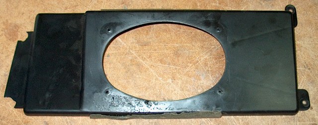
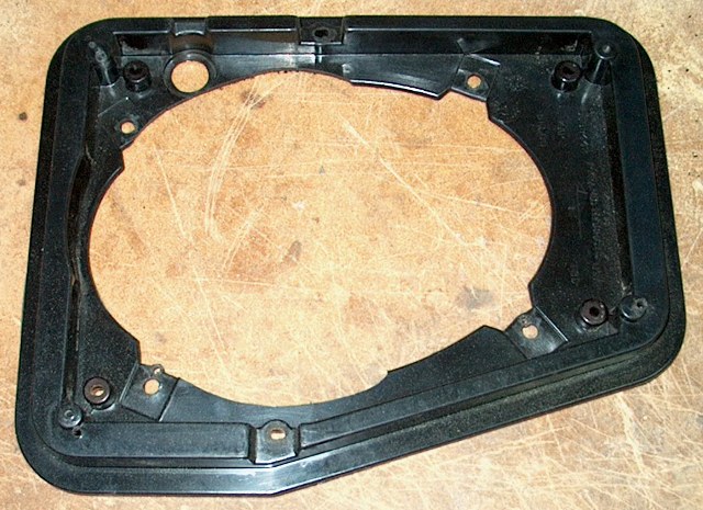
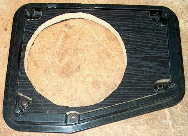
The front speakers were to be kept in the stock front location in the kick area, so I started by removing the sill cover. Remove two screws in the upper (vertical) trim and then two from the outside of the sill cover. Lift up from the rear and maneuver it over the hand brake and the front trim. This reveals the front speaker mount which is easily removed (4 7mm bolts—keep that 7mm socket driver on an electric screwdriver because you’ll use it A LOT). I didn’t take a pic of the original speakers in the mounts, but this is the mount location with the speaker and mount removed.
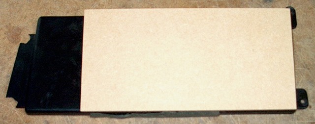
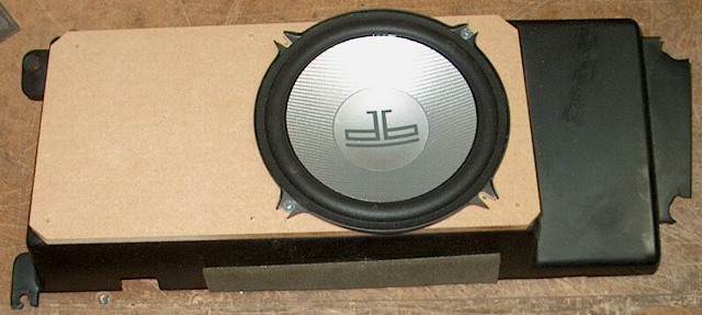
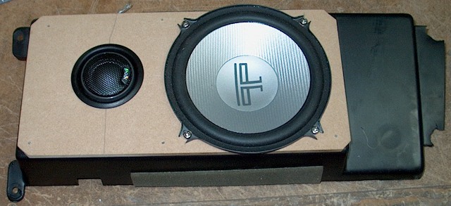
The next step was to build up the original mounting bracket to fit the new speakers. The original hole is for a 5x7 (mine had an Infinity plate mount with a 4” woofer and ľ” tweet), so making a big round hole for the 5 Ľ” wasn’t going to leave much material. I was also concerned about the depth of the new speaker, so I added a piece of Ľ” hardboard to the front of the speaker. It is screwed from the back with 6 screws and secured with epoxy. The holes are located to coincide with the grill openings in the speaker covers (permanently attached to the sill covers). The large hole was cut with a jig saw and the tweet hole with a 2” hole saw (both done with the hardboard in place to get through the plastic mount at the same time. On the back side of the mount, the 4 “towers” for the original speakers had to be removed with a hacksaw as the large hole needed to go right through two of them. The following series shows the steps for modifying the mount and attaching the speakers to the mount:
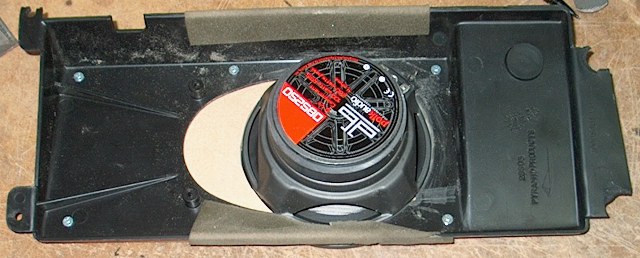
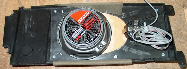
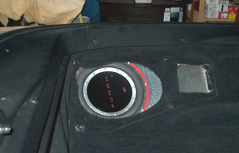
With the front speaker mount out of the way, I next tackled the rear. The RF 8” subs were to be installed in the stock rear speaker locations. The rear wells behind the speaker are probably quite a bit larger than these speakers need for an enclosure, but I decided to start simple and see how they sound in an essentially “free air” mounting. The rear mount is a plastic ring designed for a 6x9 oval. I tackled this with an approach similar to the fronts. I added ľ” MDF to the inside indent of the ring to make a flat, level surface for the 8” rounds. Before screwing the MDF in place from the back, I covered both sides with eDead material. Then I cut a round opening for the sub and screwed the speaker into place using the screws supplied.


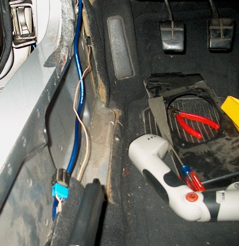
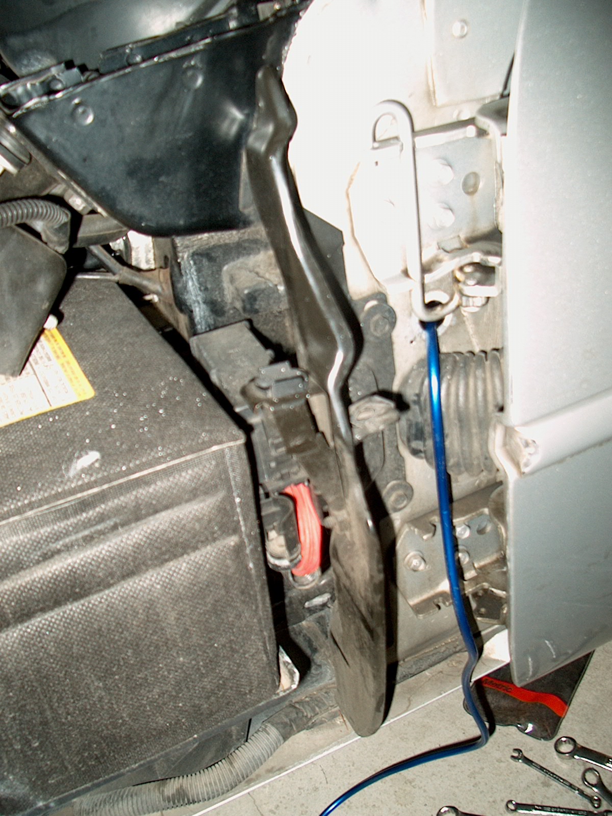
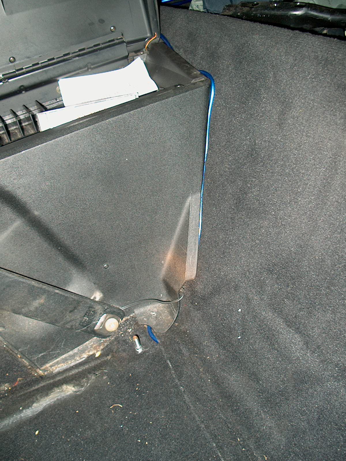
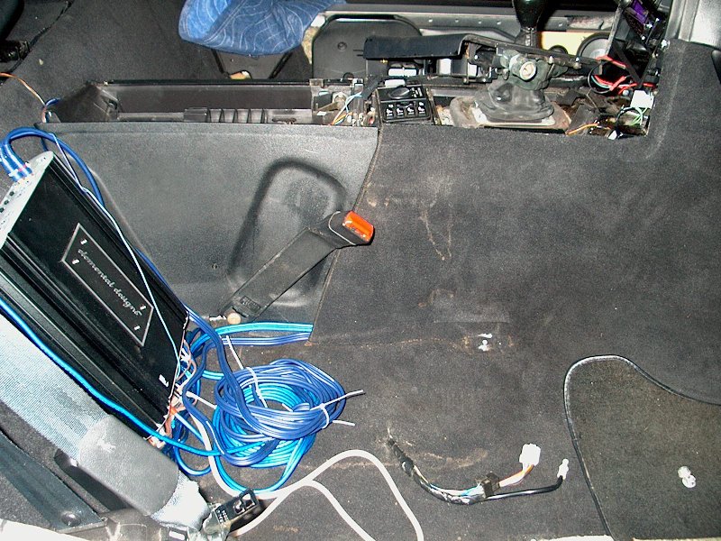
With the speaker mount fabrication out of the way, I turned to cable routing for the amp power and front speaker wires. I used an available plug in the door jamb area (just under the upper hinge) to bring the 8 ga Knukonceptz power wire into the cabin. I then ran it down the driver’s sill area under the carpet, behind the seat and up over the “hump” to the planned Amp location behind the passenger seat. You can actually see this cable (blue) in the very first picture above. Then it became clear that I could work much more easily with the seat removed. Consulting the FSM, I removed the seat bottom, unplugged all the Sport Seat connections (two power and 1 vacuum) and unbolted the seat.
I also need a place to put the crossover for the Polk component set. It was too big to fit under the speaker mount (which is where I had hoped to put it), so I settled for a spot behind the seats (sorry, no picture until the end). I ran 16 ga Knukonceptz speaker wire from the Amp location to the crossover and then two sets of wire forward under the carpet along the sill to the front speaker location. I used the eDead material on the steel behind the speaker and placed my wires into position, then mounted the front speaker. Then I mounted the rear speakers before moving on to the passenger side of the car.

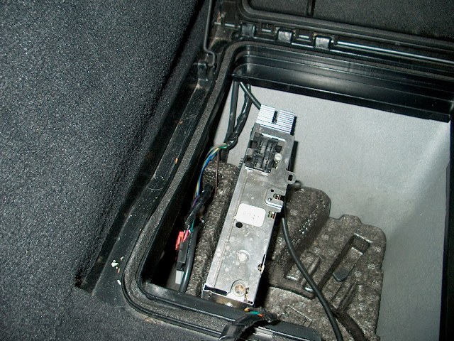
After re-arranging my garage some, I tackled the passenger side and console disassembly. Seat removal was exactly the same as the driver’s side: upper door trim, sill cover, speaker removal, seat removal. At this time I also attacked the receiver box in the bin behind the seat. There were 3 wiring harnesses into the top plus the antenna, and then two more harnesses in the bottom. The receiver itself is attached to the side wall with Velcro. Very easy to remove (the photo shows it sitting in the bin with all of the wire harnesses and antenna already removed).
Console disassembly was accomplished using “c4guru”’s instructions from the FAQ and the FSM. One note for c4guru’s instructions (http://www.c4guru.com/articles/HeadUnitRemoval.pdf): the shifter bezel on my car could not be removed without first removing the console box lid by removing it’s 4 7mm bolts. Factory HU was easily removed and tossed aside with the receiver (actually, they will be stored for possible re-use or re-install).
...MORE...
So far I like the sound and have just two issues to take care of: the HU mount looks like carp due to the lousy Metra kit and the right rear speaker grill is rattling badly and needs to be fixed (sounds great with it off). I will track down VRUMVRUM and get a better mount for the Kenwood over the winter, but it is OK for right now. I will probably do quite a bit of fiddling with the Amp settings…I’ve never had a car audio amp before. If anyone local is good with this type of thing, I would like to have another hand and ear!
The install consists of:
HU: Kenwood Excelon KDC-X590 ($229 including antenna adapter & extension and wiring harness adapter from Crutchfield)
Amp: Elemental Designs nine.4, rated 65w x 4 ($198 delivered from ED)
Front: Polk db5250 5 Ľ” component speakers ($130 delivered via eBay)
Rear: Rockford Fosgate P18S4 8” subwoofers ($73 pair from Crutchfield)
Misc: eDead sound deadener ($26 with lots left over for later), Knukonceptz amp hookup ($33), wire, shop mat’ls
First step: disconnect the negative battery terminal.
The front speakers were to be kept in the stock front location in the kick area, so I started by removing the sill cover. Remove two screws in the upper (vertical) trim and then two from the outside of the sill cover. Lift up from the rear and maneuver it over the hand brake and the front trim. This reveals the front speaker mount which is easily removed (4 7mm bolts—keep that 7mm socket driver on an electric screwdriver because you’ll use it A LOT). I didn’t take a pic of the original speakers in the mounts, but this is the mount location with the speaker and mount removed.
The next step was to build up the original mounting bracket to fit the new speakers. The original hole is for a 5x7 (mine had an Infinity plate mount with a 4” woofer and ľ” tweet), so making a big round hole for the 5 Ľ” wasn’t going to leave much material. I was also concerned about the depth of the new speaker, so I added a piece of Ľ” hardboard to the front of the speaker. It is screwed from the back with 6 screws and secured with epoxy. The holes are located to coincide with the grill openings in the speaker covers (permanently attached to the sill covers). The large hole was cut with a jig saw and the tweet hole with a 2” hole saw (both done with the hardboard in place to get through the plastic mount at the same time. On the back side of the mount, the 4 “towers” for the original speakers had to be removed with a hacksaw as the large hole needed to go right through two of them. The following series shows the steps for modifying the mount and attaching the speakers to the mount:
With the front speaker mount out of the way, I next tackled the rear. The RF 8” subs were to be installed in the stock rear speaker locations. The rear wells behind the speaker are probably quite a bit larger than these speakers need for an enclosure, but I decided to start simple and see how they sound in an essentially “free air” mounting. The rear mount is a plastic ring designed for a 6x9 oval. I tackled this with an approach similar to the fronts. I added ľ” MDF to the inside indent of the ring to make a flat, level surface for the 8” rounds. Before screwing the MDF in place from the back, I covered both sides with eDead material. Then I cut a round opening for the sub and screwed the speaker into place using the screws supplied.
With the speaker mount fabrication out of the way, I turned to cable routing for the amp power and front speaker wires. I used an available plug in the door jamb area (just under the upper hinge) to bring the 8 ga Knukonceptz power wire into the cabin. I then ran it down the driver’s sill area under the carpet, behind the seat and up over the “hump” to the planned Amp location behind the passenger seat. You can actually see this cable (blue) in the very first picture above. Then it became clear that I could work much more easily with the seat removed. Consulting the FSM, I removed the seat bottom, unplugged all the Sport Seat connections (two power and 1 vacuum) and unbolted the seat.
I also need a place to put the crossover for the Polk component set. It was too big to fit under the speaker mount (which is where I had hoped to put it), so I settled for a spot behind the seats (sorry, no picture until the end). I ran 16 ga Knukonceptz speaker wire from the Amp location to the crossover and then two sets of wire forward under the carpet along the sill to the front speaker location. I used the eDead material on the steel behind the speaker and placed my wires into position, then mounted the front speaker. Then I mounted the rear speakers before moving on to the passenger side of the car.
After re-arranging my garage some, I tackled the passenger side and console disassembly. Seat removal was exactly the same as the driver’s side: upper door trim, sill cover, speaker removal, seat removal. At this time I also attacked the receiver box in the bin behind the seat. There were 3 wiring harnesses into the top plus the antenna, and then two more harnesses in the bottom. The receiver itself is attached to the side wall with Velcro. Very easy to remove (the photo shows it sitting in the bin with all of the wire harnesses and antenna already removed).
Console disassembly was accomplished using “c4guru”’s instructions from the FAQ and the FSM. One note for c4guru’s instructions (http://www.c4guru.com/articles/HeadUnitRemoval.pdf): the shifter bezel on my car could not be removed without first removing the console box lid by removing it’s 4 7mm bolts. Factory HU was easily removed and tossed aside with the receiver (actually, they will be stored for possible re-use or re-install).
...MORE...
 10-16-2006, 12:33 AM
#2
Instructor
Thread Starter
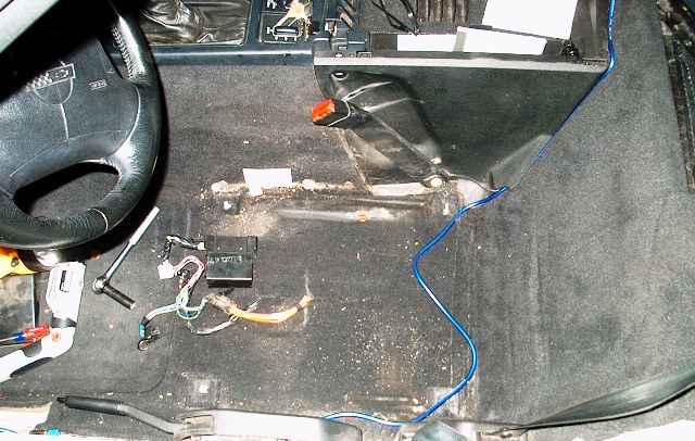
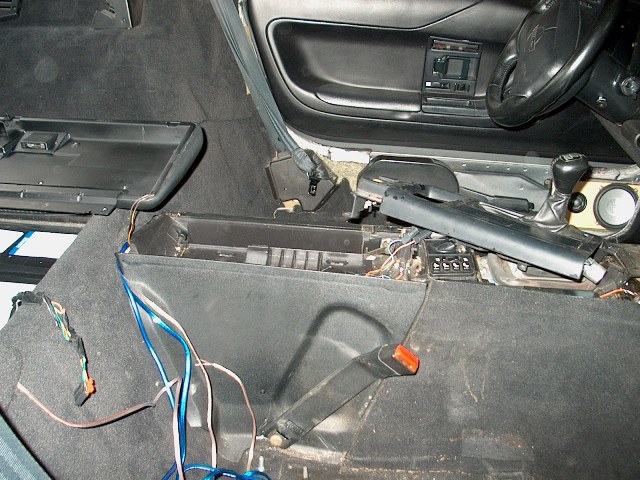
Now that I had the console apart, I did some head scratching about just where to run my power leads to the HU, the antenna and the RCAs back to the Amp. I posted a question on the board and was told by “DPG”, “pentavolvo” and “fej” to run them down the sides of the tunnel. I still didn’t get it, so I went ahead and removed the tunnel side trim panel on the passenger side (per the FSM, 5 bolts on the top and one screw on the side). This revealed PLENTY of space for my wires.
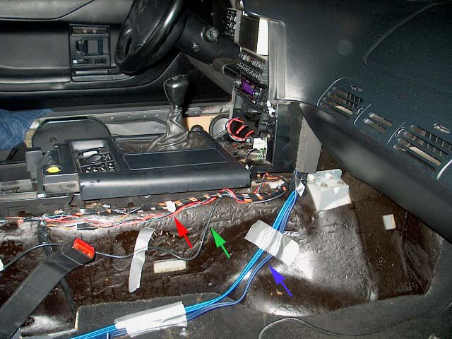
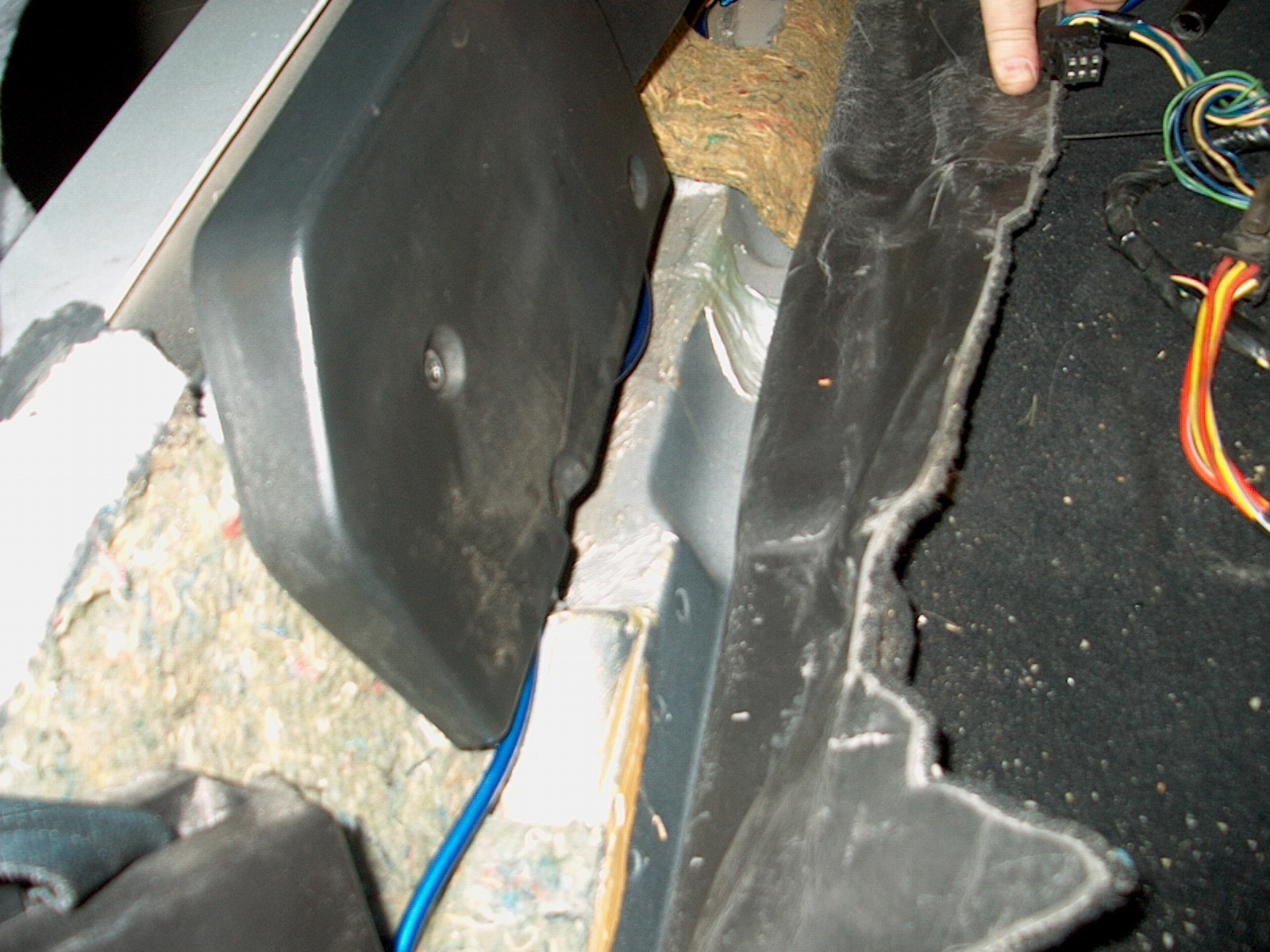
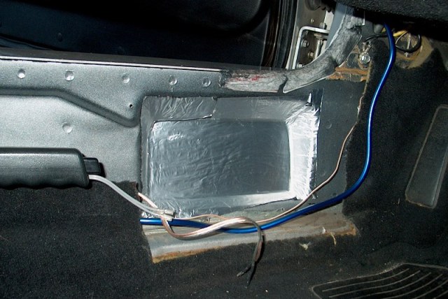
Following the advice from the FAQ, I made my power wire extension to run from the wiring harness adapter in the storage bin up to the HU. I took 4 wires (black for ground, red for switched power, yellow for constant power and blue for antenna activation), twisted them together with a drill and taped them together at intervals. This made it very easy to run. There is a big grommeted hole in the bin area that exits under the carpet on the wall behind the passenger seat. The new power harness and the antenna cable (using the adapter from Crutchfield and an extension) run through the hole, under the carpet and then along the tunnel to the HU area. In the pic above, note the arrows pointing to the power harness along the top (red) and the antenna along the side (green). You can also see the RCAs heading back to the Amp along the hump to the bottom of the tunnel (blue). These will all be covered by the tunnel side trim panel and the carpet.
I made no provision for speaker wire out of the HU to connect to the car’s original speaker harness. I ran new heavy-gauge wire to my speakers from the Amp and the RCAs will carry the HU signals to the Amp.
Next item was to finalize the runs of speaker wire. The rear speak wires were run from the mounts, under the carpet along the wheel wells and then down into the passenger compartment. The driver’s side joins the front speaker wire near the crossover and runs over the hump to the Amp. The Passenger side simply drops down to the amp. Also the passenger side front crossover, speaker wire and speaker mount were installed (using eDead behind the speaker again). The passenger side crossover is located beside the Amp on the wall.
Now that all the wires have been run, it is time to mount the Amp.
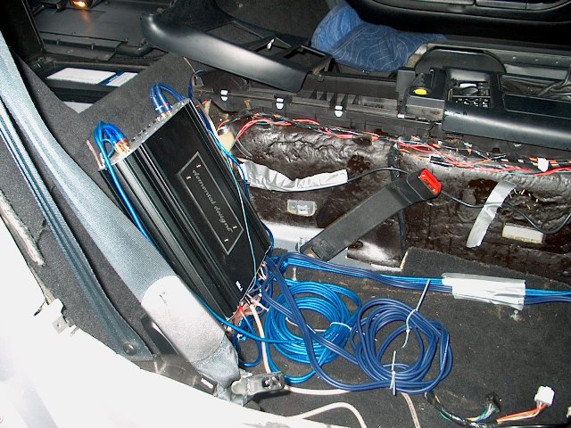
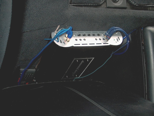
Quite a jumble of wires, there! Note that the RCAs provided by Knukonceptz in their “amp wiring kit” are WAY longer than needed in a Vette. 6 feet would have been fine in this case. You’ll see that the look is fine once the side trim panel and seat are reinstalled. I mounted the Amp with the RCAs and crossover/gain adjustments at the top and the power and speaker terminals at the bottom. Two screws at the top are connected solidly to the steel wall while the lower screws are loosely attached to just the carpet. It hangs very solidly. Note also that one of the RCAs also carries the amp-turn-on lead from the HU (a feature of the Knukonceptz cables).
With the cables and wires routed, I reinstalled the side trim panel.
Up next…the HU. All the wires have been run to the HU space (power harness, antenna, RCAs). I needed to remove the plastic support that used to hold up the rear of the factory HU as the space was too shallow for the new HU. Easily accomplished with a combination of a drill, mini-hacksaw and a little bit of brute force.
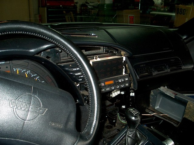
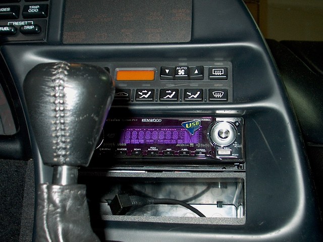
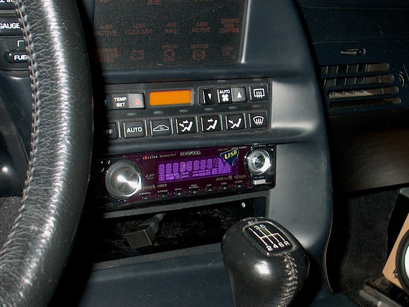
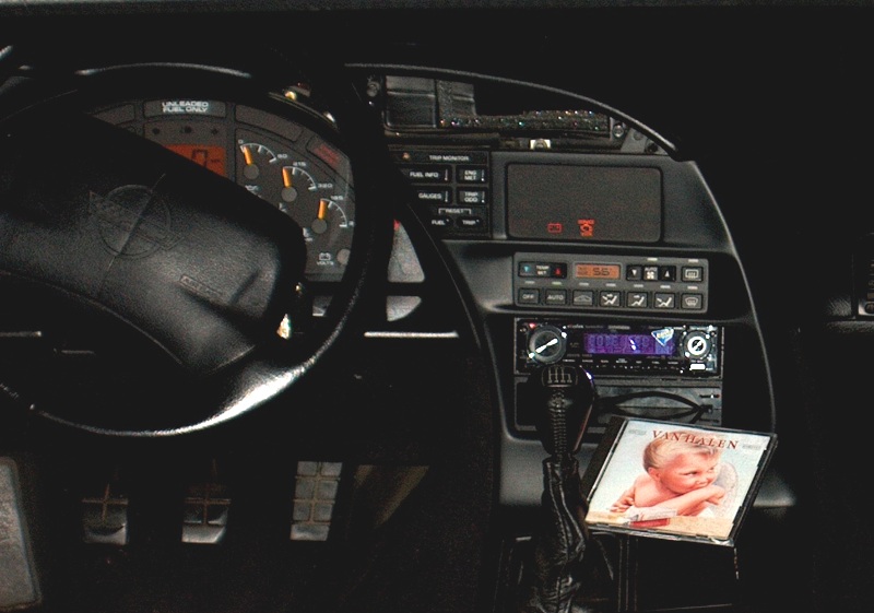
Now, let me just say that the Metra HU adapter I used SUCKS. It seems cool in that it has a “pocket” beneath the HU to take up the extra space and I used this to mount the USB connector for the Kenwood. Lining up the brackets and getting the dang thing to fit into the space was a major pain! I must have installed, adjusted, shimmed, drilled, reinstalled and fussed with it for a couple of hours just to get a so-so install. It just doesn’t fit well and the “give” in the nylon/plastic brackets just doesn’t lead to a great install. Also, the HU trim piece will not fit, leaving me with some ugly gaps and an un-centered unit. But it is installed pretty solidly. As mentioned at the start, I do intend to procure a better mount (VRUMVRUM) over the winter! So, here it is with the dash trim installed. Not too bad looking, really, but not good enough either! Note the USB cable ready for tunes from my 2 GB flash drive! (This was a main selling point for me on the Kenwood deck).
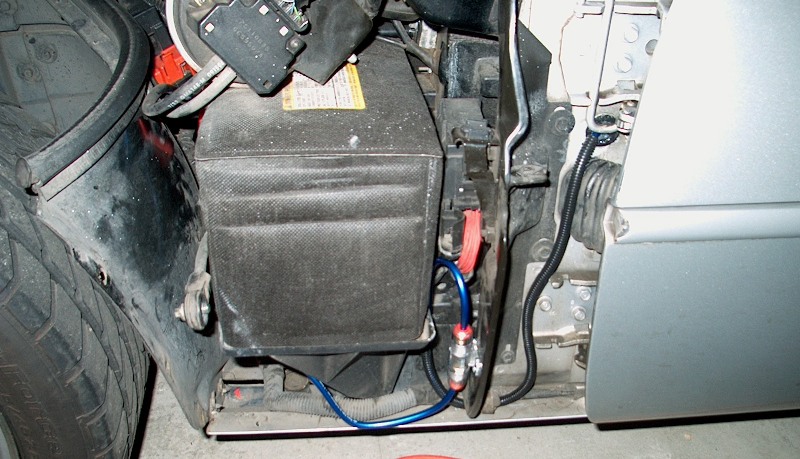
Now, where are we? Speakers…check! Amp…check! HU…check! Power…no check! I made up my Amp ground cable with a ring terminal for the seat bolt and temporarily ran two seat nuts down the stud with the ring sandwiched in between to make a solid ground connection. But ground doesn’t do any good without juice, so I returned to the battery area for my fuse and positive battery connection. I had previously removed the lower fender to access the battery (see the owner’s manual and/or FSM for removal details, but essentially 3 torx bolts in the wheel well, one 10mm bolt at the top rear of the panel and one 10 mm captured nut underneath to loosen). I cut a hole in the rubber plug for the hole in the door jamb and sealed it back in with silicone gasket/adhesive. Next I mounted the fuse holder to the stiffener panel behind and beneath the battery using two sheet metal screws with more of the silicone in the holes. I slipped a piece of split loom over the wire in the jamb area (semi-open to the elements) and slid the cable under the stiffener panel to the fuse holder (NOTE: this area is pretty tight and later I discovered that this cable is interfering with the reinstallation of the lower fender. I may well end up moving this later). Lastly, another run of the 8 ga cable was made to connect the other end of the fuse holder to the positive battery terminal.
Now we’re cooking! Double check everything and then fire it up! Awesome! Worked the first time! I spent some time playing with the Amp setup, turning up the gains and running some bass through to see how it sounded (it took a little time before I discovered the rattle/vibration in the passenger rear speaker grill). My very first music was Van Halen’s 1984 which just happened to be handy.
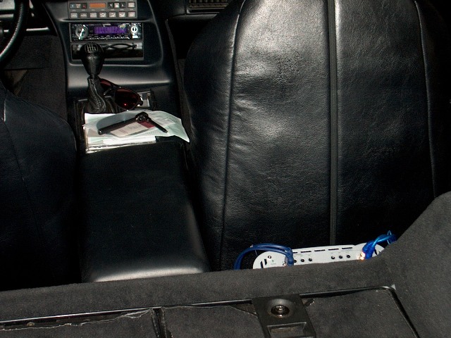
The view in from the back:
The Amp tucked in behind the passenger seat:
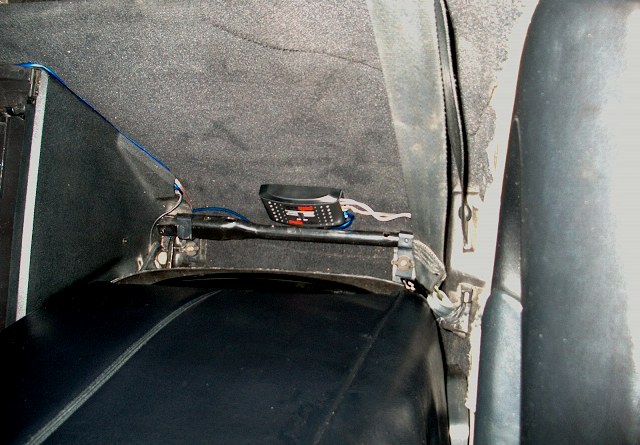
The crossover behind the driver’s seat:
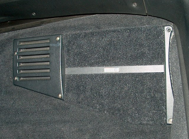
Completely stock look to the rear (and fronts, but no pics):
ADDITIONAL NOTES:
• Even a clean-looking 10-year-old car has a LOT of crap in the nooks and crannies and under the seats. Previous owners contributed a couple bucks worth of loose change for my install! I took the opportunity to vacuum and to clean the leather. I also installed new escutcheon plates on the seatbacks around the folding levers.
• Having the amp behind the passenger seat cost me about 3-4 inches of passenger leg room. I don’t ride over there, so who cares, right? WRONG! Putting the passenger seat back in was a major pain! There was precious little room to work on the rear mounting bolts because of all the gear back there. Worse, the seat could not be run BACK far enough to give clear access to the front bolts! I had to use a plain box wrench to tighten it down, turning less than Ľ turn at a time. And the nuts are a very tight fit and have to be muscled down the whole way.
• There is not nearly enough room under either seat for an amp. I did have room for my excess RCA cables, though. This is a 96 with Sport seats.
• Total install time was approximately 27 hours spread over 3 weekends. Downtime was about a month due to a vacation in there. This is NOT something I could make money at!
• It is really un-cool to get pulled over by a cop in your own neighborhood for speeding while showing your father-in-law your new Vette and stereo! 34 in a 25…but I did NOT get a ticket. Just a lecture about how my “hotrod” is too easy to make go fast and how it handles differently from other cars. We chatted a bit about his Charger cruiser while my f-i-l ran back to my house to get my insurance card.
Any and all comments and questions are welcome! Thanks!
Rob
Following the advice from the FAQ, I made my power wire extension to run from the wiring harness adapter in the storage bin up to the HU. I took 4 wires (black for ground, red for switched power, yellow for constant power and blue for antenna activation), twisted them together with a drill and taped them together at intervals. This made it very easy to run. There is a big grommeted hole in the bin area that exits under the carpet on the wall behind the passenger seat. The new power harness and the antenna cable (using the adapter from Crutchfield and an extension) run through the hole, under the carpet and then along the tunnel to the HU area. In the pic above, note the arrows pointing to the power harness along the top (red) and the antenna along the side (green). You can also see the RCAs heading back to the Amp along the hump to the bottom of the tunnel (blue). These will all be covered by the tunnel side trim panel and the carpet.
I made no provision for speaker wire out of the HU to connect to the car’s original speaker harness. I ran new heavy-gauge wire to my speakers from the Amp and the RCAs will carry the HU signals to the Amp.
Next item was to finalize the runs of speaker wire. The rear speak wires were run from the mounts, under the carpet along the wheel wells and then down into the passenger compartment. The driver’s side joins the front speaker wire near the crossover and runs over the hump to the Amp. The Passenger side simply drops down to the amp. Also the passenger side front crossover, speaker wire and speaker mount were installed (using eDead behind the speaker again). The passenger side crossover is located beside the Amp on the wall.
Now that all the wires have been run, it is time to mount the Amp.
Quite a jumble of wires, there! Note that the RCAs provided by Knukonceptz in their “amp wiring kit” are WAY longer than needed in a Vette. 6 feet would have been fine in this case. You’ll see that the look is fine once the side trim panel and seat are reinstalled. I mounted the Amp with the RCAs and crossover/gain adjustments at the top and the power and speaker terminals at the bottom. Two screws at the top are connected solidly to the steel wall while the lower screws are loosely attached to just the carpet. It hangs very solidly. Note also that one of the RCAs also carries the amp-turn-on lead from the HU (a feature of the Knukonceptz cables).
With the cables and wires routed, I reinstalled the side trim panel.
Up next…the HU. All the wires have been run to the HU space (power harness, antenna, RCAs). I needed to remove the plastic support that used to hold up the rear of the factory HU as the space was too shallow for the new HU. Easily accomplished with a combination of a drill, mini-hacksaw and a little bit of brute force.
Now, let me just say that the Metra HU adapter I used SUCKS. It seems cool in that it has a “pocket” beneath the HU to take up the extra space and I used this to mount the USB connector for the Kenwood. Lining up the brackets and getting the dang thing to fit into the space was a major pain! I must have installed, adjusted, shimmed, drilled, reinstalled and fussed with it for a couple of hours just to get a so-so install. It just doesn’t fit well and the “give” in the nylon/plastic brackets just doesn’t lead to a great install. Also, the HU trim piece will not fit, leaving me with some ugly gaps and an un-centered unit. But it is installed pretty solidly. As mentioned at the start, I do intend to procure a better mount (VRUMVRUM) over the winter! So, here it is with the dash trim installed. Not too bad looking, really, but not good enough either! Note the USB cable ready for tunes from my 2 GB flash drive! (This was a main selling point for me on the Kenwood deck).
Now, where are we? Speakers…check! Amp…check! HU…check! Power…no check! I made up my Amp ground cable with a ring terminal for the seat bolt and temporarily ran two seat nuts down the stud with the ring sandwiched in between to make a solid ground connection. But ground doesn’t do any good without juice, so I returned to the battery area for my fuse and positive battery connection. I had previously removed the lower fender to access the battery (see the owner’s manual and/or FSM for removal details, but essentially 3 torx bolts in the wheel well, one 10mm bolt at the top rear of the panel and one 10 mm captured nut underneath to loosen). I cut a hole in the rubber plug for the hole in the door jamb and sealed it back in with silicone gasket/adhesive. Next I mounted the fuse holder to the stiffener panel behind and beneath the battery using two sheet metal screws with more of the silicone in the holes. I slipped a piece of split loom over the wire in the jamb area (semi-open to the elements) and slid the cable under the stiffener panel to the fuse holder (NOTE: this area is pretty tight and later I discovered that this cable is interfering with the reinstallation of the lower fender. I may well end up moving this later). Lastly, another run of the 8 ga cable was made to connect the other end of the fuse holder to the positive battery terminal.
Now we’re cooking! Double check everything and then fire it up! Awesome! Worked the first time! I spent some time playing with the Amp setup, turning up the gains and running some bass through to see how it sounded (it took a little time before I discovered the rattle/vibration in the passenger rear speaker grill). My very first music was Van Halen’s 1984 which just happened to be handy.
The view in from the back:
The Amp tucked in behind the passenger seat:
The crossover behind the driver’s seat:
Completely stock look to the rear (and fronts, but no pics):
ADDITIONAL NOTES:
• Even a clean-looking 10-year-old car has a LOT of crap in the nooks and crannies and under the seats. Previous owners contributed a couple bucks worth of loose change for my install! I took the opportunity to vacuum and to clean the leather. I also installed new escutcheon plates on the seatbacks around the folding levers.
• Having the amp behind the passenger seat cost me about 3-4 inches of passenger leg room. I don’t ride over there, so who cares, right? WRONG! Putting the passenger seat back in was a major pain! There was precious little room to work on the rear mounting bolts because of all the gear back there. Worse, the seat could not be run BACK far enough to give clear access to the front bolts! I had to use a plain box wrench to tighten it down, turning less than Ľ turn at a time. And the nuts are a very tight fit and have to be muscled down the whole way.
• There is not nearly enough room under either seat for an amp. I did have room for my excess RCA cables, though. This is a 96 with Sport seats.
• Total install time was approximately 27 hours spread over 3 weekends. Downtime was about a month due to a vacation in there. This is NOT something I could make money at!
• It is really un-cool to get pulled over by a cop in your own neighborhood for speeding while showing your father-in-law your new Vette and stereo! 34 in a 25…but I did NOT get a ticket. Just a lecture about how my “hotrod” is too easy to make go fast and how it handles differently from other cars. We chatted a bit about his Charger cruiser while my f-i-l ran back to my house to get my insurance card.
Any and all comments and questions are welcome! Thanks!
Rob
The following users liked this post:
Tommy Swenson (06-03-2021)
10-16-2006, 12:50 AM
#3
Team Owner


That looks GREAT!!!
Congrats on the QC! VERY clean!!!!! I love it!
I am surprised that the lid had to come off the console, but that was written for a 1990-1993 type interior, so 1994-1996 could be marginally different. I will update accordingly. Thanks!
Congrats on the QC! VERY clean!!!!! I love it!
I am surprised that the lid had to come off the console, but that was written for a 1990-1993 type interior, so 1994-1996 could be marginally different. I will update accordingly. Thanks!
10-16-2006, 01:46 PM
#4
Melting Slicks

I did the same with my 94 this summer. I put 6x9's in the rear and 6 inches in the front. I currently have a small 10 inch sub box in the rear, but I'd like to have the stock look so that may change this spring.
Your install looks great.
Your install looks great.


 10-16-2006, 04:50 PM
#7
Team Owner
Member Since: Jun 2001
Location: Orlando FL
Posts: 26,196
Likes: 0
Received 0 Likes
on
0 Posts
St. Jude Donor '08-'09

Awesome job!
I REALLY like the 8" sub mounting in the back! I am getting new ideas now!
I redo my system every few months out of bordom.
BTW, I am glad to see another kenwood fan.
You went all out! I am in need of redoing all my wiring. Its almost 7 years old and getting kind of chewed up and a bit short from all the systems I've put in it over the years since I keep cutting the wires each time.
How how does that amp get pushing 2 subs stuffed behind the seat? I took my sub amp out, but will be adding it back in this weekend and was curious as to how hot they really get behind the seat. Mine has always been mounted in the rear cargo area on my custom amp deck.
10-16-2006, 07:30 PM
#8
Drifting

I wonder if there is anywhere else to mount an amp...or maybe you could do 2 smaller amps or something. I had no idea 2 8" speakers would fit in the back. How do they sound? Do they hit pretty good? I've seen a 10" tucked down into thecompartment behind the passenger seat, but I dont want to do that. So far I've just been maintaining the stock system, but I've considered mounting a sirius receiver in there somewhere.
10-18-2006, 11:45 AM
#10
Instructor
Thread Starter
I haven't been able to spend much time in the Vette since I finished. But I think it sounds pretty good for my listening habits. I wasn't looking for huge base, just to fill in the lows that the 5 1/4s can't do. I listen to rock, classic rock and "adult contemporary". I'm sure the "hit" could be improved by building sealed enclosures for them rather than just putting them into the stock locations. These guys only need .25 cu ft for a sealed box.
[edited the enclosure size...they only need .25 cu ft, not .5]
rob
[edited the enclosure size...they only need .25 cu ft, not .5]
rob
Last edited by Teddydog; 10-25-2006 at 08:32 PM.
10-25-2006, 08:31 PM
#11
Instructor
Thread Starter
Have been able to spend a bit of time now with the car...and I LIKE it! I do have a bit of alternator noise, but only noticable with low volume. I probably have my power and ground wires too close to the coils of excess RCA under the passenger seat. I also still need to deal with the loose/rattling grill on one rear speaker (sounds great without the grill installed).
This past weekend I drove my wife "to town" to run some errands and to listen to the new setup. I let her have the remote to control volume and which songs we listened to off the 2 GB Flash USB drive. She was happy with enough volume to COMPLETELY cover the road, engine and exhaust noise (Borla) on our freeway run! She likes the amount of bass, too. Neither of us is really an "audiophile", but we like our music to sound good. I can EASILY live with this setup once the fine-tuning is done.
I still need to do some work with the "gain" settings. Can someone give some idea where I "should" put these? The amp is 4 x 65 RMS (rated). The front Polks are rated 100 W RMS & 200 W Peak. The rear subs are rated 150 W RMS and 300 W Peak. Since both sets of speakers are rated well above the amp output, does that mean I should max out the gains (subject to a balanced feel)? Or is there a sweet-spot where it will put out the cleanest signal?
Thanks to everyone to has commented and made suggestions or provided assistance!
Rob
10-25-2006, 10:50 PM
#12
Instructor

Member Since: Jan 2005
Posts: 204
Likes: 0
Received 0 Likes
on
0 Posts
flatten out all EQs on the head unit, then turn up the head unit to 3/4 volume, turn the gain up until it starts to distort the speakers, turn it back down until it sounds like it isnt distorting, now adjust you crossover freq until you have the desired sound( you might have to play with the gain a little to prevent it distorting again) That should be it. Once you get the baseline on the amp you can mess with the head unit and if all else fails that you can always put it back to flat and start over. Happy tuning
10-25-2006, 10:57 PM
#13

Originally Posted by Teddydog
I still need to do some work with the "gain" settings. Can someone give some idea where I "should" put these? The amp is 4 x 65 RMS (rated). The front Polks are rated 100 W RMS & 200 W Peak. The rear subs are rated 150 W RMS and 300 W Peak. Since both sets of speakers are rated well above the amp output, does that mean I should max out the gains (subject to a balanced feel)? Or is there a sweet-spot where it will put out the cleanest signal?
http://www.icixsound.com/vb/showthread.php?t=27819
http://mobile.jlaudio.com/support_pages.php?page_id=143
etc.
10-26-2006, 02:15 AM
#14
Pro

Member Since: Aug 2005
Location: Fort Worth TX
Posts: 656
Likes: 0
Received 0 Likes
on
0 Posts

Originally Posted by bogus
That looks GREAT!!!
Congrats on the QC! VERY clean!!!!! I love it!
I am surprised that the lid had to come off the console, but that was written for a 1990-1993 type interior, so 1994-1996 could be marginally different. I will update accordingly. Thanks!
Congrats on the QC! VERY clean!!!!! I love it!
I am surprised that the lid had to come off the console, but that was written for a 1990-1993 type interior, so 1994-1996 could be marginally different. I will update accordingly. Thanks!
I cant tell you how many times I have had my HU in and out.
Gotta take it out agian to add my new XM reciver.

Oh well. I guess that comes with the territory....
10-26-2006, 10:18 AM
#16
Instructor
Thread Starter
Yes, I DID have to remove the console lid. Tried first without and the shifter cover would NOT lift off. Consulted the FSM to be sure I hadn't missed a screw and it listed the console box lid as having to be removed (easy job...just 4 bolts). Then the shifter cover came right up with no hassles.
Also, thanks for the links to the gain setting tutorials. I'm not sure I can get a DVM probe down to my speaker wire terminals and I KNOW I don't have a test-tone CD. I'll try setting by ear using Mtrhd329's method. Thanks again!
Rob
Also, thanks for the links to the gain setting tutorials. I'm not sure I can get a DVM probe down to my speaker wire terminals and I KNOW I don't have a test-tone CD. I'll try setting by ear using Mtrhd329's method. Thanks again!
Rob
10-26-2006, 02:51 PM
#17
There's free tone generation software on the web. You can then burn it to a CD for testing/calibration.
After all the effort you've gone through, take a little more time and set the amp up right rather than wagging it by ear.
After all the effort you've gone through, take a little more time and set the amp up right rather than wagging it by ear.

