
Flaming River Emerg shutoff switch
 06-10-2008, 06:11 AM
#21
Melting Slicks

Thread Starter


I used the #6 to the green coil wire and the motor would not fire. I put it on the pink to the coil and nothing. That was based on a call to flaming river. The hand written notes are the ones I took talking to another tech at FR
 06-10-2008, 07:35 AM
#22
Drifting

Member Since: May 2006
Location: Youngstown Ohio
Posts: 1,544
Likes: 0
Received 0 Likes
on
0 Posts
In an early diagram you show a magneto kill switch, are you familiar how this works?
We run a magneto and can only kill the engine if we cut off fuel, as if the magneto is turning it is generating current.
Our kill is a fuel shut off, our two electrical "kill" switches will stop you from starting the car but will not shut it down.
We run a magneto and can only kill the engine if we cut off fuel, as if the magneto is turning it is generating current.
Our kill is a fuel shut off, our two electrical "kill" switches will stop you from starting the car but will not shut it down.
06-10-2008, 08:59 AM
#23
Le Mans Master


what you mean when you say you 'put it on the pink to the coil' or
is the wire you used solid pink with no black trace?
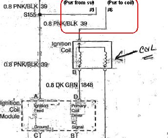
Here is the schematic revised to show the switch inserted in the 0.8
PNK/BLK wire to the coil. In this configuration, there should be battery
voltage on #6 when the OEM IGN & the Flaming River switch are both
'ON' - the car should start.
between #5 & #6? A bit of wire, a 9VDC battery and a flashlight bulb
would be sufficient. It would help to confirm that current flows across
these terminals in the 'ON' position and rule out one way in which the
switch could be defective.
.
06-10-2008, 09:45 AM
#24
Pro

Member Since: Oct 2004
Location: Reno Nv
Posts: 619
Likes: 0
Received 0 Likes
on
0 Posts
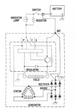
Bill Hetzel, interrupting the field looks like it would require surgery within
the alt case. OTOH, according to available info about the Delco alternator,
the 'L' circuit is a necessary external connection and appears to be used
to control charging.
"Most descriptions say that the switch grounds the field terminal thru
a resistor..."
Is it possible that the sources are speaking about a resistor that complimentsa resistor..."
the charge indicator lamp between the alternator's 'L' terminal and the
ign switch? IMO, this resistor is a back-up 'load' in the circuit to provide
fail-safe operation in the event that the bulb for the charge indicator
lamp burns out.
References for these conclusions are:
Exerpt from Helms '89 FSM (Section 6D3 - Charging System)
Operating Principals
"This generator uses at least two wire connections and a ground
path through the mounting bracket for operation. The battery positive
('Bat') terminal MUST* be connected to a battery during operation.
The second required connection is through the indicator light or suitable
external resistor to the 'L' terminal of the regulator, which serves to turn
the unit 'ON' at start-up."
(* - FSM's emphasis)
Generator Bench Check
Use a resistor of any value between 35 ohm, 5 watt, and 500 ohm.
1/2 watt between battery and "L" terminal.
Exerpt from Service Manual - Delco-Remy CS-130 and CS121 Type Alternator"This generator uses at least two wire connections and a ground
path through the mounting bracket for operation. The battery positive
('Bat') terminal MUST* be connected to a battery during operation.
The second required connection is through the indicator light or suitable
external resistor to the 'L' terminal of the regulator, which serves to turn
the unit 'ON' at start-up."
(* - FSM's emphasis)
Generator Bench Check
Use a resistor of any value between 35 ohm, 5 watt, and 500 ohm.
1/2 watt between battery and "L" terminal.
Years Used: 1986-1996
Amperages: CS-130/85-105 amps
CS-121/61-74 amps
The use of the "P", "F", and "S" terminals is optional.
.Amperages: CS-130/85-105 amps
CS-121/61-74 amps
The use of the "P", "F", and "S" terminals is optional.
- The "P" terminal is connected to the stator, and may be
connected externally to a tachometer or other device. - The "F" terminal is connected internally to field positive, and
may be used as a fault indicator. - The "S" terminal may be connected externally to a voltage,
such as battery voltage, to sense the voltage to be controlled.
06-10-2008, 09:54 AM
#25
Melting Slicks
Thread Starter
I recieved this advice last night from Jim Performance. " I would break the ignition Key On source to ecm thru this switch.This way you are killing the fuel injection system....Their instructions are based on old school no FI systems..`
The pink I was referring to is the pink into the coil. My next recomendation was the pnk/blk going into the module
I do have a on off switch for the fuel as well.
The pink I was referring to is the pink into the coil. My next recomendation was the pnk/blk going into the module
I do have a on off switch for the fuel as well.
Last edited by vstol; 06-10-2008 at 09:57 AM.
06-10-2008, 01:27 PM
#26
Le Mans Master
Sounds as though you are saying that the physical (+) wire to the coil
on the car is identified differently (PNK) than indicated on the schematic
(PNK/BLK).
I recall that you were interested in disconnecting the FI when discussing
the project in '06, too.
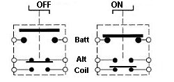
Although my vote is that the essential operations of a master shut-off
consist of disconnecting the battery, preventing the alternator from
continuing to self-power the ignition and (optionally) preventing surges
that could potentially damage components, clearly there are several
different schools of thought and strategies for implementation.
It would help satisfy my curiosity to hear at some point whether there
is conductivity between #5 & #6. I look forward to following along to
see what solution proves best for your requirements.
.
on the car is identified differently (PNK) than indicated on the schematic
(PNK/BLK).
Originally Posted by vstol
I received this advice last night from Jim's Performance.
"I would break the ignition Key On source to ecm thru this switch.
This way you are killing the fuel injection system....Their instructions
are based on old school, not FI systems..."
"I would break the ignition Key On source to ecm thru this switch.
This way you are killing the fuel injection system....Their instructions
are based on old school, not FI systems..."
the project in '06, too.
Although my vote is that the essential operations of a master shut-off
consist of disconnecting the battery, preventing the alternator from
continuing to self-power the ignition and (optionally) preventing surges
that could potentially damage components, clearly there are several
different schools of thought and strategies for implementation.
It would help satisfy my curiosity to hear at some point whether there
is conductivity between #5 & #6. I look forward to following along to
see what solution proves best for your requirements.
.
06-10-2008, 03:08 PM
#27
Melting Slicks
Thread Starter
thanks, I will check for power and the pnk/blk is the same wire to the coil and ign module by bust. Its the same coli wire just a different entry. Will try again and test the conductivity of the wires. It has got to the pink/blk.
06-10-2008, 08:50 PM
#28
Melting Slicks
Thread Starter
checked
#6 tonight and it has power when switch is on and no power when off. Did not get to check 5 but with batt switch off no pwr to the ign switch. I tried hooking number 6 to the pnk/blk again but nothing.
#6 tonight and it has power when switch is on and no power when off. Did not get to check 5 but with batt switch off no pwr to the ign switch. I tried hooking number 6 to the pnk/blk again but nothing.
06-10-2008, 10:10 PM
#29
Le Mans Master
The following questions are an attempt to understand where the power
at #6 came from. The schematic suggests to me that #5 & #6 are
two sides of a switched circuit with no connection to the other two
switched circuits contained within the housing.
- In checking #6, is it correct to say that you used a test light or
similar with one lead attached to #6 and the other to ground? - Did #6 have a wire connected to it? If so, what colour was it and
what was it attached to at the other end? - Is it correct to say that nothing was attached to #5 during the test?
06-10-2008, 10:56 PM
#30
Le Mans Master
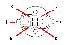
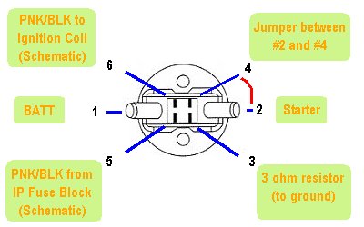
The terminals are numbered (& prospectively wired) as follows, correct?
 .
.
- 1 (Bat) - - - - 2 (Srt) -
- 3 (Res) - - - - 4 (Alt) -
- 5 (Coi) - - - - 6 (Ign) -
Does the terminal layout look like the following?- 3 (Res) - - - - 4 (Alt) -
- 5 (Coi) - - - - 6 (Ign) -
06-11-2008, 06:13 AM
#31
Melting Slicks
Thread Starter
will get back to you tonight, many thanks
Q 1 I used a meter
Q2 no wire attached
Q3 will check
Will also check to see if its wired the way you have in the diagram.
Q 1 I used a meter
Q2 no wire attached
Q3 will check
Will also check to see if its wired the way you have in the diagram.
06-11-2008, 09:24 AM
#32
Pro
Member Since: Oct 2004
Location: Reno Nv
Posts: 619
Likes: 0
Received 0 Likes
on
0 Posts
Well, Just to confuse things, the Formula E (avitar) runs a FI, 2300 Mazda. The alternator is an option. The kill switch is a standard 2 post without the 2 small alternator posts. When you install the alternator kit there is no change to the kill switch.
So, in this application, the kill switch just cuts the main battery cable and has no means to groung the alternator field.
Go Figure.
So, in this application, the kill switch just cuts the main battery cable and has no means to groung the alternator field.
Go Figure.
06-11-2008, 07:50 PM
#33
Melting Slicks
Thread Starter
First off I will call Flaming River once aagain in the am to ask them again how to wire this. The FR switch when oriented the way you have drawn below is almost the same with the exception that 3 and 6 are switched. 1 left/2 right 6/5 and 4/3. That said I have it wire per the FR techs advice different than what they have due to the ECM/FI. That said I have:
1/batt
2/starter
jmp wire 2/4 (Scribbled notes on the side of the daigram)
5 to the ign
3 resistor.
with that what is your recomendation so I can poke FR in the eye and see what they have to say. Many thanks we are killing a lot of snakes with this one.W
1/batt
2/starter
jmp wire 2/4 (Scribbled notes on the side of the daigram)
5 to the ign
3 resistor.
with that what is your recomendation so I can poke FR in the eye and see what they have to say. Many thanks we are killing a lot of snakes with this one.W
Last edited by vstol; 06-12-2008 at 07:03 AM.
06-12-2008, 02:14 AM
#34
Le Mans Master
Can you confirm that the car can be started now by restoring the wiring
to the OEM configuration to rule out unanticipated electrical damage
during work to install the Master Shut-Off?
Here is the FR schematic with additional detail, followed by a revision
of the terminal layout based on my understanding your remarks above.
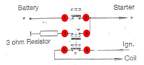
 In the image above, the comments for terminals #5 & #6 refer to
PNK/BLK coded wires. This is to indicate inserting the FR Shut-off in
the coil circuit in a manner roughly similar to that shown below.
However, aside from the fuse upstream in the PNK/BLK circuit, I do
not know what difference there would be between doing it as per
the above versus running a wire from the ignition switch to terminal
#5 and then continuing from #6 into the PNK/BLK coil wire (which is
what I understand that you have done and tested without success
so far.)
If you check that the car will start with the original wiring and then
insert the switch in the PNK/BLK circuit and find that the car won't
start, even after performing the usual tests to verify workmanship,
then I will be stymied.
I notice that the auxiliary contacts (#3 to #6) are rated for 5V
continuous max operating voltage in the specs provided by FR.
This is less than the 12+ VDC that the ign requires for best performance
- perhaps someone can comment about how this pole on the switch is
or is not adequate in practice for the coil circuit.
As for contacting Flaming River, my vote is to be cordial. Perhaps
provide a link to this thread so they can comment to you or contribute
directly here in the thread. At this stage, I feel there is something
trivial that is interferring with completion of the install.
.
to the OEM configuration to rule out unanticipated electrical damage
during work to install the Master Shut-Off?
Originally Posted by vstol
The FR switch when oriented the way you have drawn below is
almost the same with the exception that 3 and 6 are switched.
1 left/2 right 6/5 and 4/3.
That said, I have it wired per the FR tech's advice - different than
what they have due to the ECM/FI.
I have:
almost the same with the exception that 3 and 6 are switched.
1 left/2 right 6/5 and 4/3.
That said, I have it wired per the FR tech's advice - different than
what they have due to the ECM/FI.
I have:
1/batt
2/starter
jmp wire 2/4 (Scribbled notes on the side of the diagram)
5 to the ign
3 resistor.
2/starter
jmp wire 2/4 (Scribbled notes on the side of the diagram)
5 to the ign
3 resistor.
of the terminal layout based on my understanding your remarks above.
PNK/BLK coded wires. This is to indicate inserting the FR Shut-off in
the coil circuit in a manner roughly similar to that shown below.
not know what difference there would be between doing it as per
the above versus running a wire from the ignition switch to terminal
#5 and then continuing from #6 into the PNK/BLK coil wire (which is
what I understand that you have done and tested without success
so far.)
If you check that the car will start with the original wiring and then
insert the switch in the PNK/BLK circuit and find that the car won't
start, even after performing the usual tests to verify workmanship,
then I will be stymied.
I notice that the auxiliary contacts (#3 to #6) are rated for 5V
continuous max operating voltage in the specs provided by FR.
This is less than the 12+ VDC that the ign requires for best performance
- perhaps someone can comment about how this pole on the switch is
or is not adequate in practice for the coil circuit.
As for contacting Flaming River, my vote is to be cordial. Perhaps
provide a link to this thread so they can comment to you or contribute
directly here in the thread. At this stage, I feel there is something
trivial that is interferring with completion of the install.
.
06-12-2008, 09:36 AM
#35
Melting Slicks
Thread Starter
Left a call back for the FR tech who did the wiring diagram & testing of the cutoff switch. Will let you know the results. They also have the thread
06-12-2008, 06:32 PM
#36
Melting Slicks
Thread Starter
Can you confirm that the car can be started now by restoring the wiring
to the OEM configuration to rule out unanticipated electrical damage
during work to install the Master Shut-Off?
I can not get to OEM configuration the switch is tied into the entire system. As mentioned I took the LT 4 and put it into my 64 Grand Sport. No response from FR yet
to the OEM configuration to rule out unanticipated electrical damage
during work to install the Master Shut-Off?
I can not get to OEM configuration the switch is tied into the entire system. As mentioned I took the LT 4 and put it into my 64 Grand Sport. No response from FR yet
06-20-2008, 06:25 AM
#38
Melting Slicks
Thread Starter
I will call FR this morning. Customer service is not up to par. In the mean time I replaced the resistor, rechecked its grd but no change in the outcome
06-20-2008, 11:23 AM
#39
Melting Slicks
Thread Starter
All right, talked to FR and this is what we came up with. Since this is an ECM car, the pnk/bk from the Ign Module needs to be cut, then the number five goes to the pnk/blk from the ign modulel and #6 will be inline and attach to the pnk/blk to complete the circuit. Will try and get back to you.
06-20-2008, 11:35 AM
#40
Melting Slicks
Thread Starter
All right, talked to FR and this is what we came up with. Since this is an ECM car, the pnk/bk from the Ign Module needs to be cut, then the number five goes to the pnk/blk from the ign modulel and #6 will be inline and attach to the pnk/blk to complete the circuit. Will try and get back to you.

