
Aftermarket fuel gauge on stock tanks...? How to..
 01-01-2011, 01:06 PM
#1
Advanced

Thread Starter
Member Since: Jun 2007
Posts: 81
Likes: 0
Received 0 Likes
on
0 Posts

Hello
Since it seems as there always is someone that has an explanation on things, i am posting up..
We are going trough a C6 Race car here in Norway. The car has a stand alone engine harness, and a separate harness for the lights, and so.. (so nothing left of the stock wiring.
We are running the stock fuel tanks, but do not have a fuel level gauge. I want to get one in there.
Any one having experience, or know how on how to get such a function, what gauge, and how do you hook up?
Am i right when it looks like there is two fuel level sending units? One in each tank?
Brgds
 01-02-2011, 10:58 PM
#2

Here’s what I did. You will need an Auto Meter Programmable Fuel Level Gage. The part number for the Phantom series is 5710. There are other styles available, and can be found on their website.
This procedure will wire the two fuel level senders in series so that the fuel level becomes the sum of the two.
Unfortunately, the Auto Meter gage is made to work with a maximum resistance of 270 ohms. When we add the 2 senders together, they total 500 ohms at Empty. To overcome this, I installed a 560 ohm resistor in parallel with the senders, to reduce the total resistance. However, this causes the resistance change to be non-linear from Full to Empty {for resistors in parallel, the total resistance RT=1/(1/R1+1/R2)} so the gage must be programmed using the values below.
This will cause the gage to remain on the Full mark until about the tank is about 7/8, and at 3/4 tank, the gage will read about 7/8. From 1/2 to Empty, the gage will be pretty accurate.
Refer to the schematic below for a description of what to do with the existing wiring.
1. Cut wire number 2759 at connector D6 (C2). If you don’t have a factory ECU, you won’t need to do this, as it obviously is not connected.
2. Connect wire number 1937 to ground.
3. Connect wire number 1936 to the purple lead for the fuel gage. Use a spade connector so that it can be quickly disconnected for calibration.
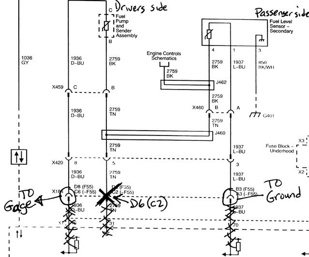
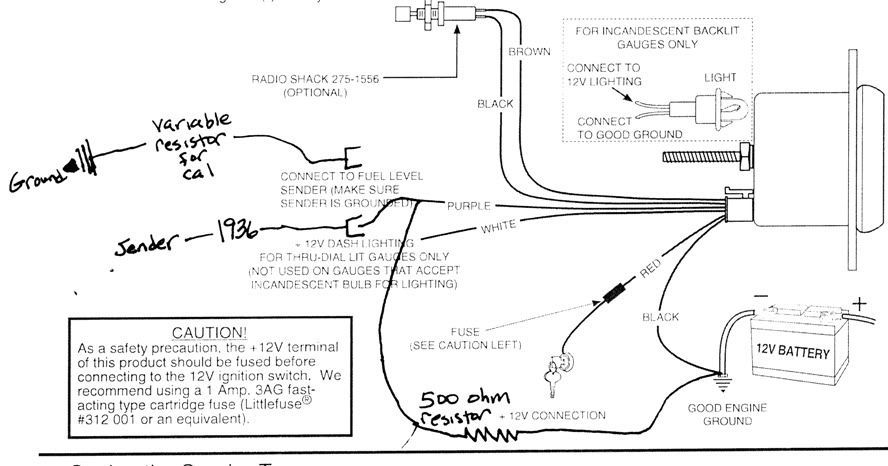
Refer to the schematic for the fuel gage below.
4. Wire the gage as shown, adding a 560 ohm resistor between the purple wire and ground. Wire it as shown such that when the sender is disconnected , the 560 ohm resistor remains connected between the purple wire and ground .
5. To calibrate the gage, disconnect the purple wire from the sender perform the custom calibration, replacing steps 6 and 7 in the Auto Meter instructions with the following steps 6 and 7.
6. Adjust the pot to 500 ohms. Now connect the pot to the gage and momentarily (less than one second), push the switch (touch brown to black wire) to capture the Empty calibration point. After approximately one second, the pointer will move to just above the Full mark.
7. Disconnect the pot from the gage and adjust the pot to 150 ohms. Now connect the pot to the gage and momentarily press the switch (touch brown to black wire) to capture the Full calibration point.
Turn off power to the gage. Remove the pot, connect the sender and restore power to the gage, and it will now read actual fuel level.
The other option is to install two fuel gages, one for each tank, or a single gage with a toggle switch to swap between the two. Hint: passenger side empties first.
This procedure will wire the two fuel level senders in series so that the fuel level becomes the sum of the two.
Unfortunately, the Auto Meter gage is made to work with a maximum resistance of 270 ohms. When we add the 2 senders together, they total 500 ohms at Empty. To overcome this, I installed a 560 ohm resistor in parallel with the senders, to reduce the total resistance. However, this causes the resistance change to be non-linear from Full to Empty {for resistors in parallel, the total resistance RT=1/(1/R1+1/R2)} so the gage must be programmed using the values below.
This will cause the gage to remain on the Full mark until about the tank is about 7/8, and at 3/4 tank, the gage will read about 7/8. From 1/2 to Empty, the gage will be pretty accurate.
Refer to the schematic below for a description of what to do with the existing wiring.
1. Cut wire number 2759 at connector D6 (C2). If you don’t have a factory ECU, you won’t need to do this, as it obviously is not connected.
2. Connect wire number 1937 to ground.
3. Connect wire number 1936 to the purple lead for the fuel gage. Use a spade connector so that it can be quickly disconnected for calibration.
Refer to the schematic for the fuel gage below.
4. Wire the gage as shown, adding a 560 ohm resistor between the purple wire and ground. Wire it as shown such that when the sender is disconnected , the 560 ohm resistor remains connected between the purple wire and ground .
5. To calibrate the gage, disconnect the purple wire from the sender perform the custom calibration, replacing steps 6 and 7 in the Auto Meter instructions with the following steps 6 and 7.
6. Adjust the pot to 500 ohms. Now connect the pot to the gage and momentarily (less than one second), push the switch (touch brown to black wire) to capture the Empty calibration point. After approximately one second, the pointer will move to just above the Full mark.
7. Disconnect the pot from the gage and adjust the pot to 150 ohms. Now connect the pot to the gage and momentarily press the switch (touch brown to black wire) to capture the Full calibration point.
Turn off power to the gage. Remove the pot, connect the sender and restore power to the gage, and it will now read actual fuel level.
The other option is to install two fuel gages, one for each tank, or a single gage with a toggle switch to swap between the two. Hint: passenger side empties first.
Last edited by FlamingZ06; 01-02-2011 at 11:03 PM.
12-28-2016, 07:45 AM
#4
Racer

How did this work out for you guys long term? I am going to use my AIM MXG as my aftermarket fuel gauge, I like your idea of a toggle switch for the two tanks very much! I'm thinking a SPDT switch to flip between the two!