
DRM Transmission Cooler Install Process - Pictures and Helpful Hints.
 08-18-2012, 08:24 PM
#1
Safety Car

Thread Starter
Member Since: Nov 2000
Location: Shenandoah Valley Virginia
Posts: 4,549
Likes: 0
Received 27 Likes
on
24 Posts

I have been getting the dreaded transmission overheat message the last several events. I have tried the band aid fixes of wrapping the exhaust pipes with header wrap and changing the fluid to Redline, but they did not work. I decided to order a DRM transmission cooler kit since it was well priced and I had been very satisfied with their engine oil cooler kit.
When I received the kit, there were no instructions or flow diagrams in the box so I emailed Randy at DRM. He sent me a flow diagram and several images of typical installations. The kit includes the cooler, all braided lines cut to length and assembled, pump and all fittings. There are several items that you will have to fabricate and furnish yourself including cooler mounting brackets, all your fasteners, wiring materials and switch.
Below you will find a pictorial guide to my installation. Total time to install was about 6 hours spread over several days using a lift. If you have to do the work on jack stands, count on at least 2 - 3 more hours time. Hopefully this install information will make the job easier for future persons using this kit.
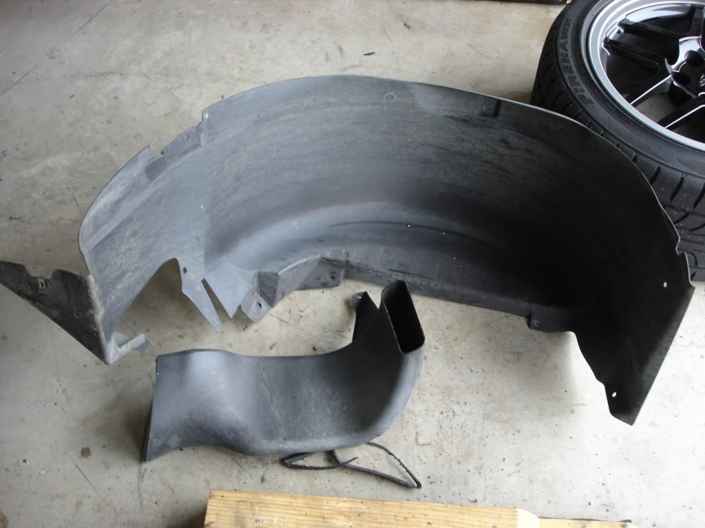
The first step is to remove the left rear wheel, inner fender liner and brake duct. There are about 10 screws holding the liner to the car and a couple more holding the duct.
Next step is to trial fit the cooler in its location to start to figure out how to make supporting brackets. The cooler has to mount directly in front of the cooling duct to take maximum advantage of all the air flow. To use the entire area and maximize flow through the fins, it must be mounted at an angle rather than straight vertical.
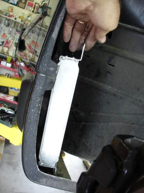
To get the needed clearances for the cooler and pump, I had to trim off about 1" of the rubber ducting attached to the scoop. The space behind the fender liner is tight for everything involved. I used a coping saw and just cut off the flexible rubber surround. You could take the duct out to cut, but two of the attachment bolts are a PITA to get to.
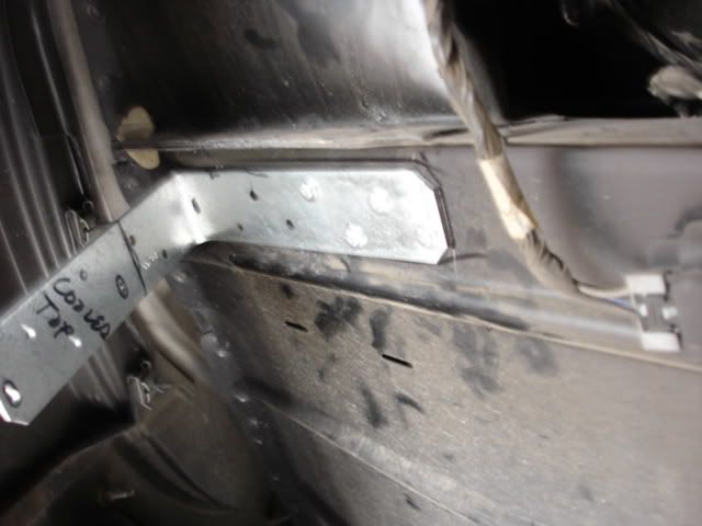
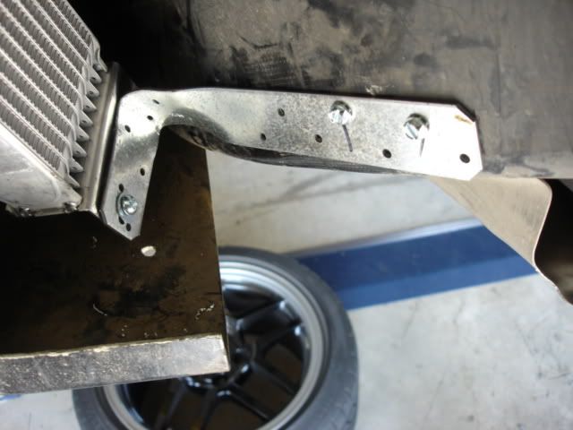
To mount the cooler you must fabricate two brackets. I used 3/16" galvanized iron brackets from the big box store that are used in framing of decks. Cost about $1.50 each and have a lot of holes already predrilled making install much easier. This was a very time consuming item. Had to bend and modify many times till I got a good fit. Attached the bracket to the car's sheet metal with self tapping sheet metal screws and star lock washers. This is the top bracket.
This is the bottom bracket.
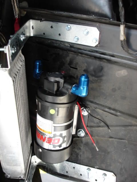
Next comes the mounting of the pump. I found some rubber grommets that fit in the holes on the bracket, and used self tapping sheet metal screws and star lock washers to mount. The pump bracket had to be removed and slightly bent for better contact with the curved mounting surface.
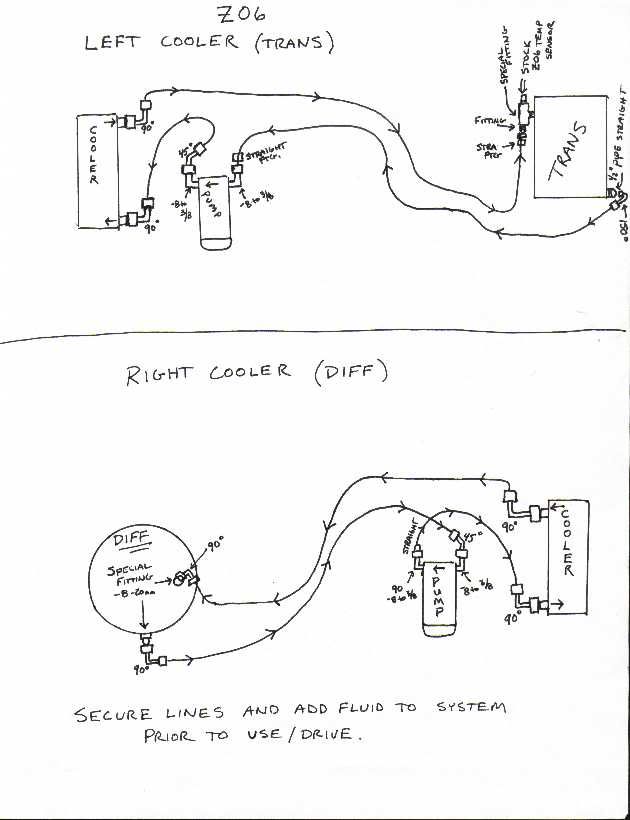
Next job was to start the plumbing. I drained the transmission and laid out all of the various hoses and fittings for use and used the supplied diagram to figure out what went where. There are a lot of specific angle bends used to make the hoses run properly and keep them away from critical areas. This is the supplied flow diagram with fitting information.
Next all of the fittings that were pipe thread had to have teflon tape applied to insure that no leaks happened. The system is low pressure, so the possibility of a leak is greatly minimized. The white is the tape, the other ends are the crimp braided line fittings and need no additional sealer.
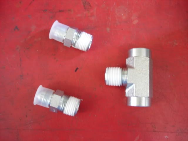
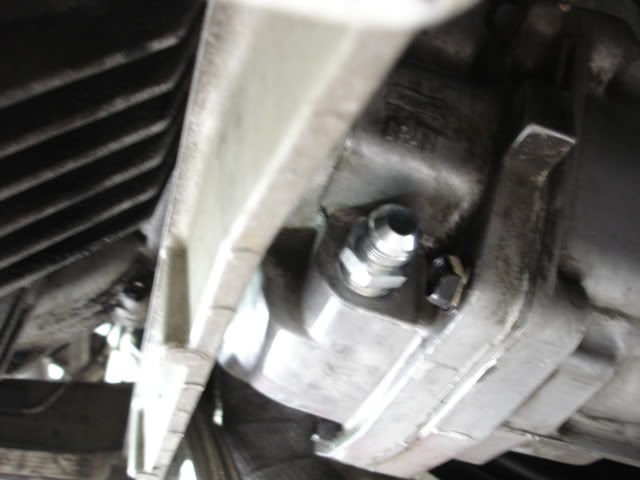
Next comes the install of the drain and fill fittings. These replace the stock drain plug and the temperature sensor in the fill location. The temp sensor fits in one end of the return cool oil fitting so you don't loose the warning indicator. This is the fitting replacing the drain plug.
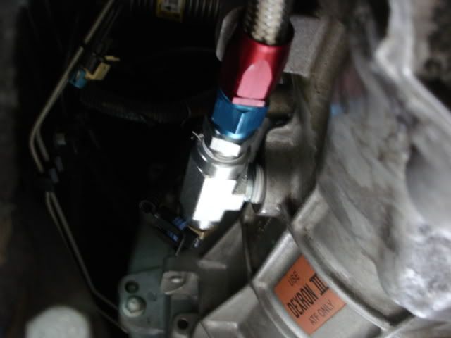
This is the "T" fitting that acts as the return cool oil inlet and also mounts the temp sensor in the other. Be sure to mount this fitting with the temp sensor slightly elevated above center to allow for easy filling of the fluid. The fitting does not flow nearly as fast as the open hole, so take it easy with your pump when refilling the tranny.
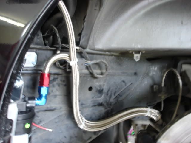
Now you can start the line install. Follow the diagram with the various fittings and hose lengths. They basically run from the transmission over and through the end of the crossmenber and up to the pump and cooler. Be very careful of your routing so you don't come into contact with any brake lines or the CV joint boot. Once installed tie every thing down with multiple Zip ties.
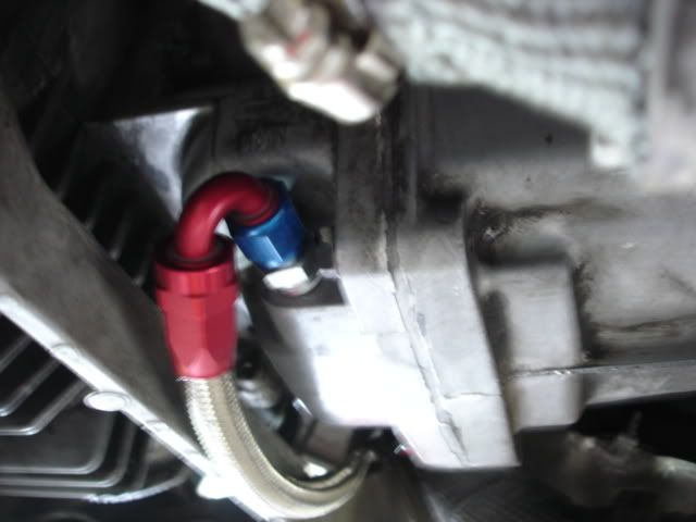
Oil pickup connection.
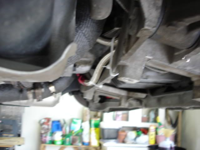
Up and over the crossmenber.
Pump and cooler connections. Zip tie to secure.
Once you have all the lines in place, you have to wire the pump and on / off switch. There are several ways that you can run the electric power. I grounded directly to one of my bracket screws since they went into the frame. Hot side can be taken from the fuse box near the battery or from other locations. Run wire through one of the existing rubber grommets in the firewall. Just to be safe, I added a fuse in line on the circuit. Picked up an inline fuse holder at Autozone when I got the wire and switch. Make sure your switch is at least 20 AMP capable at 12V. Feed wire should be at least 14 gauge, use 12 gauge if you are going to feed both a tranny and diff cooler from the same lead.
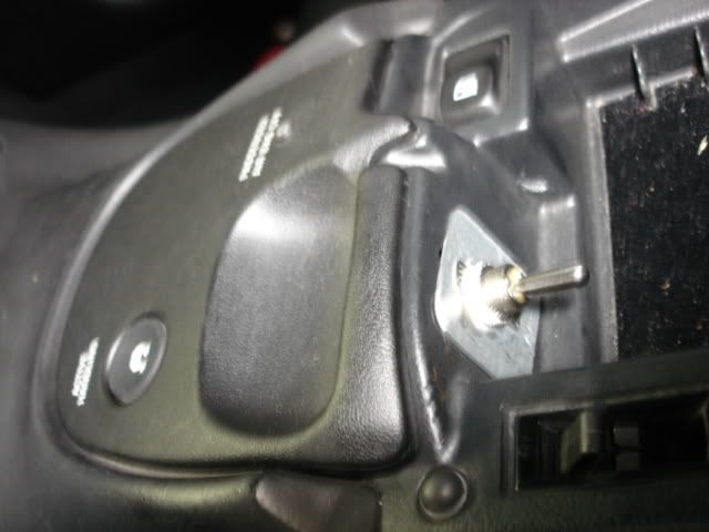
I removed the power plug in the console and mounted my on off switch in that location. It is hidden, but easily accessable. Made a small aluminum plate to cover the hole and use as the mounting surface. Drilled a hole in the wheel well tub and ran the power wire from the pump under the carpet into the console to the switch.
NOTE: it is very important to make strong electrical connections to avoid future problems. Always use gromets, crimp connectors, and thoroughly tape connections to avoid corrosion.
Here is the switch and mounting plate in the console.
Now it is time to fill the system. Using the new fitting, fill slowly till overflowing like usual and replace the temp sensor. Now you have to run the pump and fill the lines and cooler. Turn the switch on and run for 30 seconds or so. You can hear the pump prime itself and you will know when the sound changes that you are pumping oil. Remove temp sensor and continue filling system till full just like normal. The extra plumbing takes an additonal quart to fill so figure on 4 3/4 quarts total. Install sensor and connect the wiring harness to the plug.
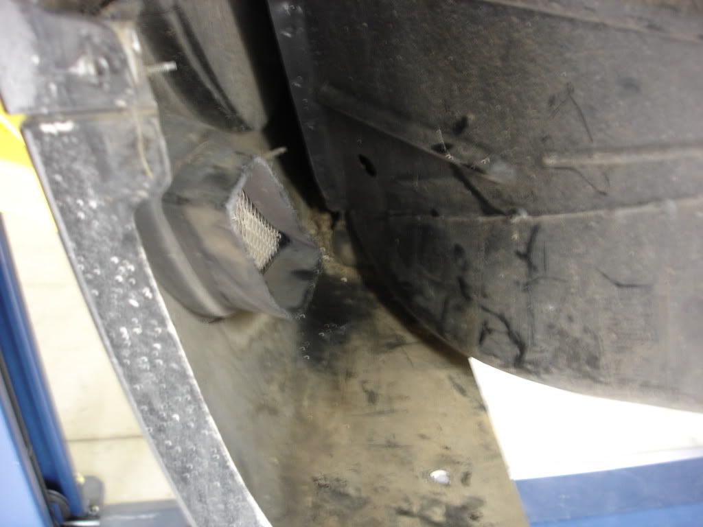
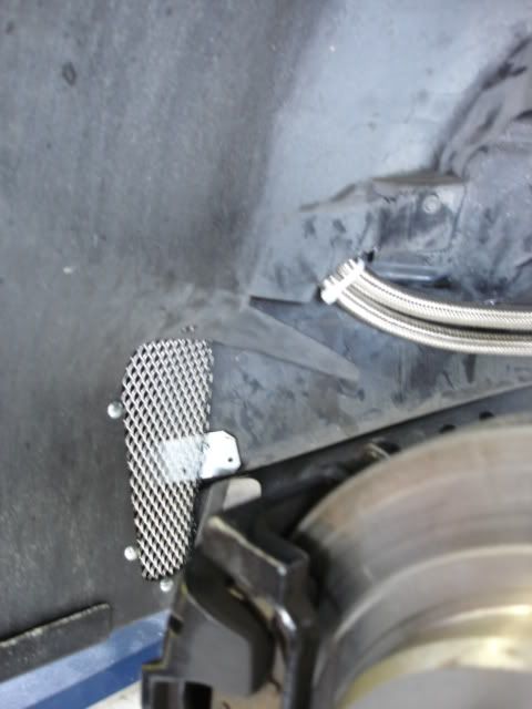
The final thing to do is reinstall the fender well. You have a big hole in it where the cooling duct used to go. I used some "Gutter Guard" expanded aluminum available at big box home store to seal the hole. This material will allow all intake air to exit and also keep track turds and junk out of the inside of the wheel well. I also had to trim a small amount of material around the hoses where they pass through to allow the wheel well to sit tight against the frame.
I hope that this post will help future users in their kit installation. The first one is tough. especially without detailed install instructions. This guide should help you avoid some fo the pitfalls that I encountered. These instructions can also be used for the install of the DRM differential cooler kit. It is the same, just a mirror image on the right side of the car.
When I received the kit, there were no instructions or flow diagrams in the box so I emailed Randy at DRM. He sent me a flow diagram and several images of typical installations. The kit includes the cooler, all braided lines cut to length and assembled, pump and all fittings. There are several items that you will have to fabricate and furnish yourself including cooler mounting brackets, all your fasteners, wiring materials and switch.
Below you will find a pictorial guide to my installation. Total time to install was about 6 hours spread over several days using a lift. If you have to do the work on jack stands, count on at least 2 - 3 more hours time. Hopefully this install information will make the job easier for future persons using this kit.
The first step is to remove the left rear wheel, inner fender liner and brake duct. There are about 10 screws holding the liner to the car and a couple more holding the duct.
Next step is to trial fit the cooler in its location to start to figure out how to make supporting brackets. The cooler has to mount directly in front of the cooling duct to take maximum advantage of all the air flow. To use the entire area and maximize flow through the fins, it must be mounted at an angle rather than straight vertical.
To get the needed clearances for the cooler and pump, I had to trim off about 1" of the rubber ducting attached to the scoop. The space behind the fender liner is tight for everything involved. I used a coping saw and just cut off the flexible rubber surround. You could take the duct out to cut, but two of the attachment bolts are a PITA to get to.
To mount the cooler you must fabricate two brackets. I used 3/16" galvanized iron brackets from the big box store that are used in framing of decks. Cost about $1.50 each and have a lot of holes already predrilled making install much easier. This was a very time consuming item. Had to bend and modify many times till I got a good fit. Attached the bracket to the car's sheet metal with self tapping sheet metal screws and star lock washers. This is the top bracket.
This is the bottom bracket.
Next comes the mounting of the pump. I found some rubber grommets that fit in the holes on the bracket, and used self tapping sheet metal screws and star lock washers to mount. The pump bracket had to be removed and slightly bent for better contact with the curved mounting surface.
Next job was to start the plumbing. I drained the transmission and laid out all of the various hoses and fittings for use and used the supplied diagram to figure out what went where. There are a lot of specific angle bends used to make the hoses run properly and keep them away from critical areas. This is the supplied flow diagram with fitting information.
Next all of the fittings that were pipe thread had to have teflon tape applied to insure that no leaks happened. The system is low pressure, so the possibility of a leak is greatly minimized. The white is the tape, the other ends are the crimp braided line fittings and need no additional sealer.
Next comes the install of the drain and fill fittings. These replace the stock drain plug and the temperature sensor in the fill location. The temp sensor fits in one end of the return cool oil fitting so you don't loose the warning indicator. This is the fitting replacing the drain plug.
This is the "T" fitting that acts as the return cool oil inlet and also mounts the temp sensor in the other. Be sure to mount this fitting with the temp sensor slightly elevated above center to allow for easy filling of the fluid. The fitting does not flow nearly as fast as the open hole, so take it easy with your pump when refilling the tranny.
Now you can start the line install. Follow the diagram with the various fittings and hose lengths. They basically run from the transmission over and through the end of the crossmenber and up to the pump and cooler. Be very careful of your routing so you don't come into contact with any brake lines or the CV joint boot. Once installed tie every thing down with multiple Zip ties.
Oil pickup connection.
Up and over the crossmenber.
Pump and cooler connections. Zip tie to secure.
Once you have all the lines in place, you have to wire the pump and on / off switch. There are several ways that you can run the electric power. I grounded directly to one of my bracket screws since they went into the frame. Hot side can be taken from the fuse box near the battery or from other locations. Run wire through one of the existing rubber grommets in the firewall. Just to be safe, I added a fuse in line on the circuit. Picked up an inline fuse holder at Autozone when I got the wire and switch. Make sure your switch is at least 20 AMP capable at 12V. Feed wire should be at least 14 gauge, use 12 gauge if you are going to feed both a tranny and diff cooler from the same lead.
I removed the power plug in the console and mounted my on off switch in that location. It is hidden, but easily accessable. Made a small aluminum plate to cover the hole and use as the mounting surface. Drilled a hole in the wheel well tub and ran the power wire from the pump under the carpet into the console to the switch.
NOTE: it is very important to make strong electrical connections to avoid future problems. Always use gromets, crimp connectors, and thoroughly tape connections to avoid corrosion.
Here is the switch and mounting plate in the console.
Now it is time to fill the system. Using the new fitting, fill slowly till overflowing like usual and replace the temp sensor. Now you have to run the pump and fill the lines and cooler. Turn the switch on and run for 30 seconds or so. You can hear the pump prime itself and you will know when the sound changes that you are pumping oil. Remove temp sensor and continue filling system till full just like normal. The extra plumbing takes an additonal quart to fill so figure on 4 3/4 quarts total. Install sensor and connect the wiring harness to the plug.
The final thing to do is reinstall the fender well. You have a big hole in it where the cooling duct used to go. I used some "Gutter Guard" expanded aluminum available at big box home store to seal the hole. This material will allow all intake air to exit and also keep track turds and junk out of the inside of the wheel well. I also had to trim a small amount of material around the hoses where they pass through to allow the wheel well to sit tight against the frame.
I hope that this post will help future users in their kit installation. The first one is tough. especially without detailed install instructions. This guide should help you avoid some fo the pitfalls that I encountered. These instructions can also be used for the install of the DRM differential cooler kit. It is the same, just a mirror image on the right side of the car.
Last edited by CHJ In Virginia; 08-28-2012 at 04:35 PM.

The following 3 users liked this post by CHJ In Virginia:
 08-19-2012, 01:19 AM
#3
Melting Slicks


Nice writeup. 
 08-21-2012, 09:30 PM
#5
Pro

05-02-2014, 03:55 PM
#6
Intermediate


Member Since: Sep 2006
Posts: 28
Likes: 0
Received 0 Likes
on
0 Posts
Thanks for the write up! I'm going to start this task tomorrow and didn't want to call Randy Rippie a dozen times  I've already talked to him a couple times, he is a really great guy and very helpful.
I've already talked to him a couple times, he is a really great guy and very helpful.
Last edited by XFordGuy; 05-04-2014 at 09:41 AM.
02-03-2017, 10:32 AM
#7

Bringing this back now that you've had time with it....
I'm wanting to grab one of these (in addition to an oil and diff cooler) and have a few questions for you (or anyone else who's run one of these)
I'm curious what kind of a drop in temps you saw?
How hard do you think it would be to install a thermal switch so that whenever the temp gets upto about 220* (or whatever) it automatically kicks on? (I'm assuming there is a lot of access and area to the lines where you could do that...?
Lastly, do you know how many gph that pump is?
Thanks for taking the time to do such a good write up!
Last edited by nskyline34; 02-03-2017 at 10:32 AM.
02-04-2017, 08:19 PM
#8
Safety Car
Thread Starter
Member Since: Nov 2000
Location: Shenandoah Valley Virginia
Posts: 4,549
Likes: 0
Received 27 Likes
on
24 Posts
Bringing this back now that you've had time with it....
I'm wanting to grab one of these (in addition to an oil and diff cooler) and have a few questions for you (or anyone else who's run one of these)
I'm curious what kind of a drop in temps you saw?
How hard do you think it would be to install a thermal switch so that whenever the temp gets upto about 220* (or whatever) it automatically kicks on? (I'm assuming there is a lot of access and area to the lines where you could do that...?
Lastly, do you know how many gph that pump is?
Thanks for taking the time to do such a good write up!
I'm wanting to grab one of these (in addition to an oil and diff cooler) and have a few questions for you (or anyone else who's run one of these)
I'm curious what kind of a drop in temps you saw?
How hard do you think it would be to install a thermal switch so that whenever the temp gets upto about 220* (or whatever) it automatically kicks on? (I'm assuming there is a lot of access and area to the lines where you could do that...?
Lastly, do you know how many gph that pump is?
Thanks for taking the time to do such a good write up!
I used several DRM cooler products on my C5, and they all performed satisfactorily.
Engine Oil cooler - DO THIS ONE FIRST ! I dropped from temps in the low 300 range to a steady 260 deg using this cooler. AT VIR in august with an ambient temperature of over 100 deg, my oil never got over 260 deg. during a 30 minute session, this cooler works.
Transmission cooler this one works also. Did not have temperature readings, but the cooler kept the transmission cool enough to not trigger the warning sensor on the same 100 deg day.
Did not use the differential cooler, but probably should have.
On the engine oil cooler, I used a Mocal 150 deg thermostat in series with the cooler. Thermostat bypasses the cooler entirely till the engine oil reaches 150 deg. then opens gradually to avoid thermal shock. That way you do not have extended engine warm up time. IMHO a temperature switch on a diff or trans is overkill. Just have a toggle like in my post and turn it on as you are leaving the staging area.
Pump in the transmission cooler is small since the volume of fluid is only 3 1/2 quarts including what is in the cooler. Pump would be measured in gallons per minute not hour. 3-4 GPM would offer a lot of circulation for that fluid volume. No longer have the car so I can not tell you exactly.
I like DRM products, they are well thought out and work !
Last edited by CHJ In Virginia; 02-04-2017 at 08:35 PM.
05-13-2018, 02:09 PM
#10

I realize it's been a few years, but if you're still around, thanks very much for the great write-up, and all of the pictures. I bought a C5 a couple months ago and ordered these coolers shortly afterward, and the lack of instructions was kind of intimidating. It would have taken forever to figure this out on my own.
Can anyone tell me where the fuel tanks located, relative to where the brackets were attached to the frame? I assume they're fairly close, but I haven't taken apart anything in that area yet. so I'm a little nervous...
Can anyone tell me where the fuel tanks located, relative to where the brackets were attached to the frame? I assume they're fairly close, but I haven't taken apart anything in that area yet. so I'm a little nervous...
05-15-2018, 07:05 PM
#11


I realize it's been a few years, but if you're still around, thanks very much for the great write-up, and all of the pictures. I bought a C5 a couple months ago and ordered these coolers shortly afterward, and the lack of instructions was kind of intimidating. It would have taken forever to figure this out on my own.
Can anyone tell me where the fuel tanks located, relative to where the brackets were attached to the frame? I assume they're fairly close, but I haven't taken apart anything in that area yet. so I'm a little nervous...
Can anyone tell me where the fuel tanks located, relative to where the brackets were attached to the frame? I assume they're fairly close, but I haven't taken apart anything in that area yet. so I'm a little nervous...
Thanks also to Randy at DRM, I thought the fittings were missing, he felt bad and of course offered to reimburse me for the fittings I "finall" found. then I thought, did i miss them in the packing? Sure enough unwadded all the paper, clonk they fell on the floor! Thanks again, Randy. Grandpa Bob
05-15-2018, 07:41 PM
#12
Thanks for the info, I appreciate it.