66 horn relay wiring
 08-07-2007, 10:42 PM
#1
Instructor

Thread Starter

Member Since: Jun 2007
Location: lake elsinore Ca
Posts: 103
Likes: 0
Received 0 Likes
on
0 Posts
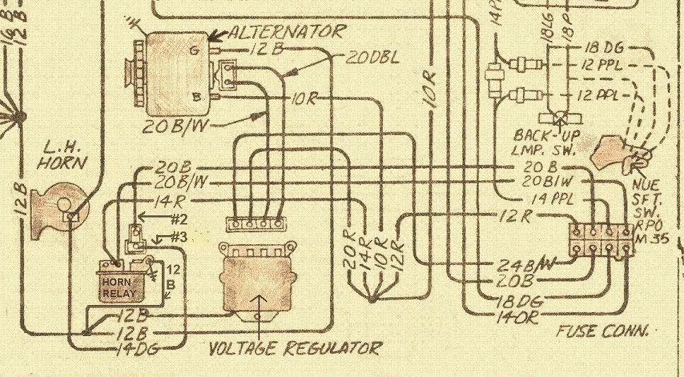
How do the wires on the 66 horn connect big red big black medium green and small black wire. The green and small black wire have plastic plugs. Any help?
 08-08-2007, 12:59 AM
#2


Big Red..screws into the terminal marked 'Batt'
Big Black...lug goes on screw that attaches relay to rad support (ground)
Dark Green and small Black...to the terminals marked 1 and 2
But you are missing one, the Black with White stripe...goes to the same terminal as Big Red. You need this. It is for your Ammeter.
Corrected version of the wiring diagram shown below.
Last edited by buns; 08-08-2007 at 09:32 PM. Reason: added #2 and #3 terminals to wiring diagram
08-08-2007, 01:14 AM
#3
Instructor
Thread Starter
Member Since: Jun 2007
Location: lake elsinore Ca
Posts: 103
Likes: 0
Received 0 Likes
on
0 Posts
Yeah Buns Thanks
Sorry. The little wire was paired with the red on the lug. My relay has the two plastic connector plug-ins on the relaty marked 2 and 3 #2 is closest to the mounting bolt hole. Based on this does green go into 2 or 3? By the way great diagram.
Sorry. The little wire was paired with the red on the lug. My relay has the two plastic connector plug-ins on the relaty marked 2 and 3 #2 is closest to the mounting bolt hole. Based on this does green go into 2 or 3? By the way great diagram.
08-08-2007, 12:00 PM
#4
Team Owner


Member Since: Oct 2000
Location: Washington Michigan
Posts: 38,899
Received 1,856 Likes
on
1,099 Posts

Does your horn relay have the two spade connectors oriented as a "T" as shown in Buns' diagram? If so, the green wire (12V feed to the horns) goes on the top cross of the "T", and the black wire (ground from the horn button) goes on the vertical leg of the "T". 
08-08-2007, 12:35 PM
#5
Instructor
Thread Starter
Member Since: Jun 2007
Location: lake elsinore Ca
Posts: 103
Likes: 0
Received 0 Likes
on
0 Posts
No they are not T'd. The unit is a delco remy, and the two spade connectors are in line with one another perpendicular to the mounting surface.
http://i206.photobucket.com/albums/b.../hornrelay.jpg
http://i206.photobucket.com/albums/b.../hornrelay.jpg
08-08-2007, 02:19 PM
#6
Team Owner
Member Since: Oct 2000
Location: Washington Michigan
Posts: 38,899
Received 1,856 Likes
on
1,099 Posts
Put 12V on the screw terminal buss, ground on the attaching bracket; use a jumper wire from the ground side and touch it to each of the spade terminals - whichever one makes the relay "click" is where the black wire goes.
 08-08-2007, 09:41 PM
#8

I checked my horn relay , it is the same as hellamog's. Black wire goes to #2, Dark Green to #3. The #3 spade has a small tit (which is easily broken off) , and the connector has a groove to match it.
I also updated the wiring diagram above, for future referance.

