Replacing the road draft tube with a PCV valve on the SB400 in the 56
 04-05-2008, 09:17 PM
#1
Race Director


Thread Starter
Member Since: Mar 2001
Location: Mustang OK
Posts: 13,847
Received 3,768 Likes
on
1,670 Posts
2023 C1 of the Year Finalist - Modified
2015 C1 of the Year Finalist

Several of you know that I have a "home made" road draft tube in the SB400 in the 56. Well, its just fine, but I'm finally tired of the oil film on the underside of the car so, I'm removing the road draft tube and replacing it with a PCV valve.
Everyone wants to see pictures of "how it was done", so here they are with explanations.
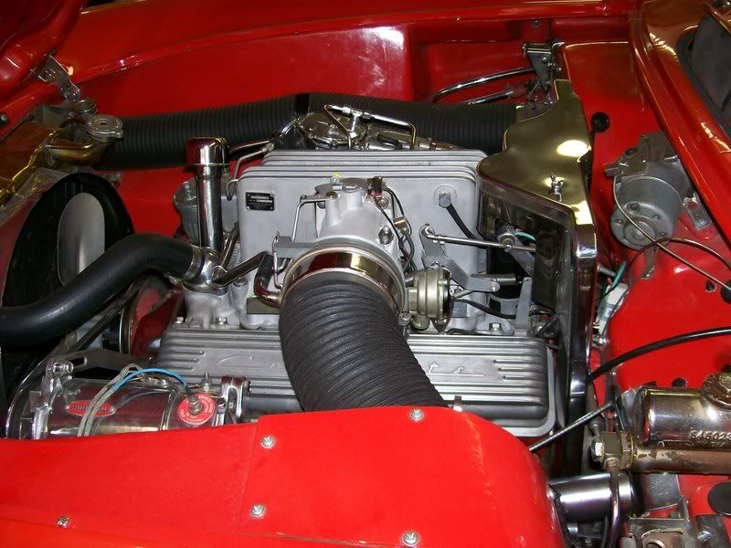
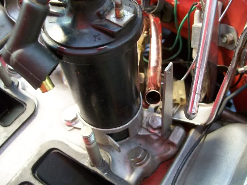
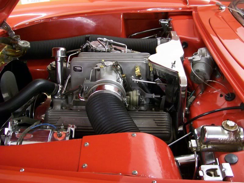
Here is the left side of the engine before. The fitting on the left rear of the plenum is for the vacuum advance on the dist.
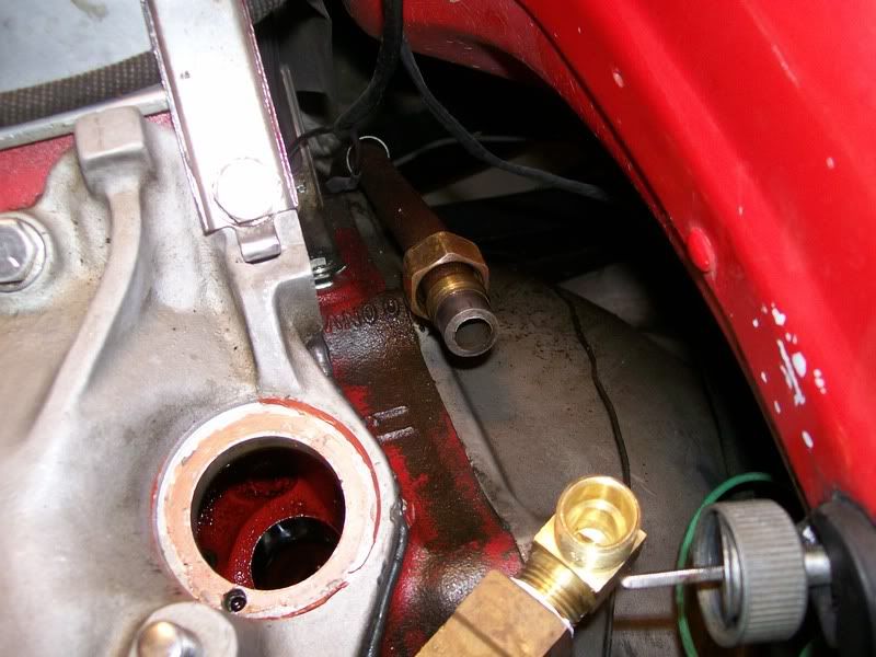
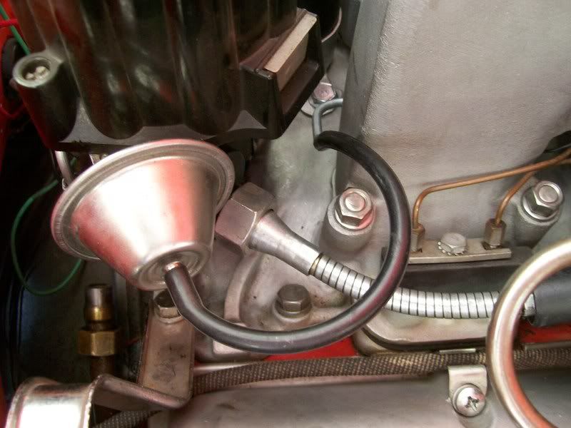
Here you can see the old "home made" road draft tube after everything was disconnected.
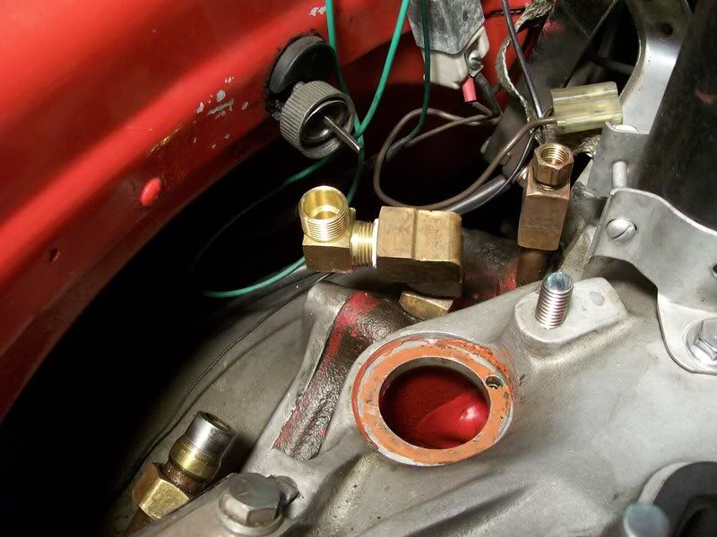
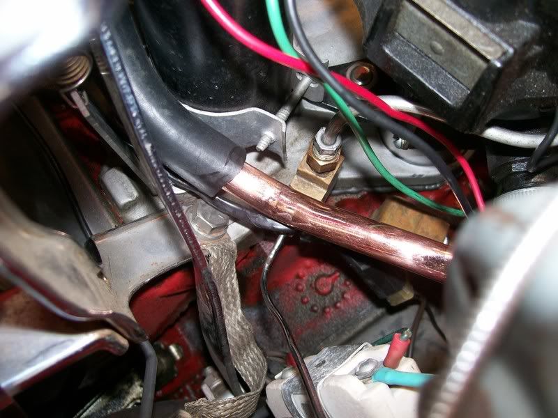
Here is where the brass fittings come up through the bell housing flange (sorry, no pictures below the flange or inside the lifter valley) with a new fitting for the new vent tube for the PCV valve.
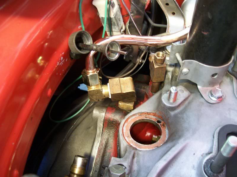
Two pictures of the new formed tube for the PCV valve.
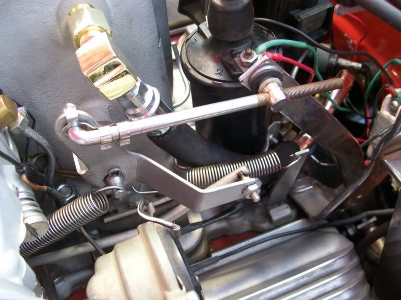
New fitting on the side of the plenum, PCV valve (replacement
PCV valve from NAPA for a 63 w/FI) and 1/2in hose connecting PCV valve and new vent tube (this is virtually identical to how it was done on a 63 FI car on the other side of the plenum).
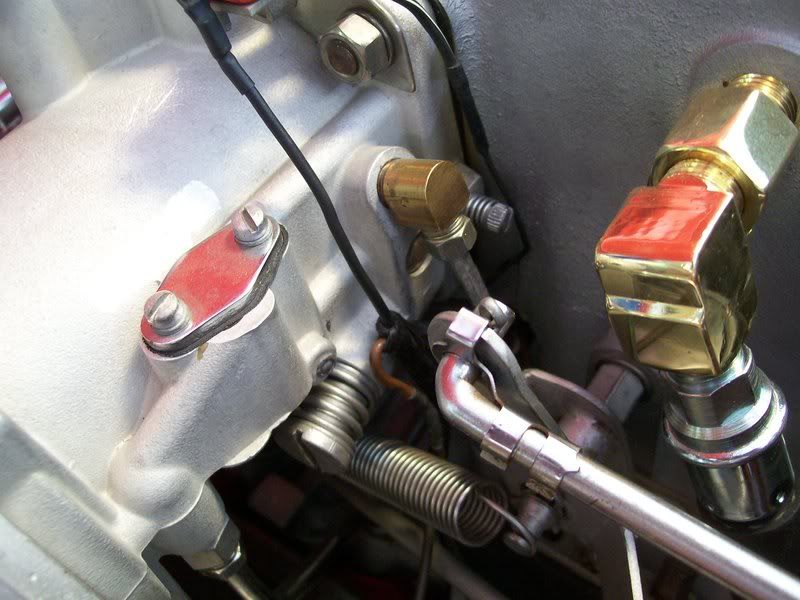
Since I used the plenum port that WAS for the vac adv, I had to relocate the source. The fitting/3/16 tube on the air meter are for the vac adv. I routed it down and under the plenum, then out the rear with a vac hose to the dist.
Everyone wants to see pictures of "how it was done", so here they are with explanations.
Here is the left side of the engine before. The fitting on the left rear of the plenum is for the vacuum advance on the dist.
Here you can see the old "home made" road draft tube after everything was disconnected.
Here is where the brass fittings come up through the bell housing flange (sorry, no pictures below the flange or inside the lifter valley) with a new fitting for the new vent tube for the PCV valve.
Two pictures of the new formed tube for the PCV valve.
New fitting on the side of the plenum, PCV valve (replacement
PCV valve from NAPA for a 63 w/FI) and 1/2in hose connecting PCV valve and new vent tube (this is virtually identical to how it was done on a 63 FI car on the other side of the plenum).
Since I used the plenum port that WAS for the vac adv, I had to relocate the source. The fitting/3/16 tube on the air meter are for the vac adv. I routed it down and under the plenum, then out the rear with a vac hose to the dist.
Last edited by DZAUTO; 04-07-2008 at 01:19 PM.
 04-05-2008, 09:39 PM
#2
Drifting


great pics and write up DZ. could you describe what you did to get from under that bellhousing flange into the valley??? just curious.
i'm building a 383 for my vette and didn't want to tap into the "corvette" valve covers so i drilled and tapped into the vertical part of the block beside the dist. then i pulled the big vacuum tube out of the rear of the holley baseplate and tapped it fo a screw in pcv, installed a 90 dedree AN fitting in the hole i tapped in the block and bent up an aluminum hard line to run under the dist to the PCV at the back of the carb. it's almost invisible. it took 10 times as long for me to figure out what i was going to do than do it!!

i'm building a 383 for my vette and didn't want to tap into the "corvette" valve covers so i drilled and tapped into the vertical part of the block beside the dist. then i pulled the big vacuum tube out of the rear of the holley baseplate and tapped it fo a screw in pcv, installed a 90 dedree AN fitting in the hole i tapped in the block and bent up an aluminum hard line to run under the dist to the PCV at the back of the carb. it's almost invisible. it took 10 times as long for me to figure out what i was going to do than do it!!
 I' don't quite see where you pulled the vacuum source for the distributor from?
04-05-2008, 10:33 PM
I' don't quite see where you pulled the vacuum source for the distributor from?
04-05-2008, 10:33 PM
#4
12.14 w/ the original 327


Tom, thanks for the pics and explanation.
From a functionality stand point, is there any reason you couldn't drill and tap the block in the areas shown in white (assuming a later block than the one in the pic)? Essentially, the block would be drilled on the vertical surface of the block, just below the intake, making sure to clear the distributor hole, etc.

I was thinking of drilling through the area shown, then running a 90* fitting, and screwing a PCV valve into it.
Wes
From a functionality stand point, is there any reason you couldn't drill and tap the block in the areas shown in white (assuming a later block than the one in the pic)? Essentially, the block would be drilled on the vertical surface of the block, just below the intake, making sure to clear the distributor hole, etc.
I was thinking of drilling through the area shown, then running a 90* fitting, and screwing a PCV valve into it.
Wes
04-05-2008, 10:54 PM
#5
Drifting
Tom, thanks for the pics and explanation.
From a functionality stand point, is there any reason you couldn't drill and tap the block in the areas shown in white (assuming a later block than the one in the pic)? Essentially, the block would be drilled on the vertical surface of the block, just below the intake, making sure to clear the distributor hole, etc.
I was thinking of drilling through the area shown, then running a 90* fitting, and screwing a PCV valve into it.
Wes

actually looking at the pic again mine is drilled just above the right box..
Last edited by mechron; 04-05-2008 at 11:00 PM. Reason: adding a line
04-06-2008, 12:55 AM
#6
Race Director
Thread Starter
Member Since: Mar 2001
Location: Mustang OK
Posts: 13,847
Received 3,768 Likes
on
1,670 Posts
2023 C1 of the Year Finalist - Modified
2015 C1 of the Year Finalist
Mechron-Wes,
In the picture below, you can lookd into the dist hole and see something brass. That is part of the fitting on the inside of the valley. I drilled through the back of the block, below the bell housing flange, and threaded the hole in the block. Then I coated the threads with JB Weld, screwed in a fitting, then screwed screwed the fitting that is partially visible onto the threads and coated the thread/joint with JB Weld. On the flywheel side of the block, I screwed on a brass elbow (3/8 pipe thread), then drilled a hole through the bell housing flange, ran a length of brass pipe with threads on eadh end through the hole, screwed it into the elbow below the bell housing flange and then screwed an elbow (which you can see in the same picture) onto that length of pipe.
In the lifter valley, I ran a length of brass pipe from the fitting at the rear all the way up to the front of the lifter valley with several small holes drillet into the bottom side of the pipe to allow crankcase pressure into the pipe, and then go out the rear of the block into the plumbing. The object of course, was to allow internal vapors/pressure to escape from the crankcase. It worked as intended, but a road draft tube with escaping vapors under the car is continually depositing an oily mess on the underside. Originall, I did not want to install a PCV valve, but after several years of cleaning the oily film from the underside, something had to change. I've given this a lot of thought over the years, and each time I finally come back to the PCV valve installation. So, that's what and why I did it.
The addition of the PCV valve was rather straight forward, just time consuming and agrivating. As you can see, I had to remove the injector and dist. The biggest aggrivation has been getting the injector re-tuned to compensate for the added air/vapor volume coming from the PCV valve port.
Last edited by DZAUTO; 04-06-2008 at 01:06 AM.
04-06-2008, 01:10 AM
#8
Race Director
Thread Starter
Member Since: Mar 2001
Location: Mustang OK
Posts: 13,847
Received 3,768 Likes
on
1,670 Posts
2023 C1 of the Year Finalist - Modified
2015 C1 of the Year Finalist
See that small brass elbow fitting with the 3/16 tubing going straight down, on the side of the air meter? That's my manifold vacuum source for the vac adv.
I ran it down, then back under the plenum and out the rear between the rear legs of the plenum.
04-06-2008, 01:31 AM
#9
12.14 w/ the original 327
Tom, thank you for the follow-up. I'm kicking around doing this to my truck's old 383 and putting it in the 62 with closed valve covers and a 461 intake.
BTW, barring the unexpected, we'll be heading your way in mid-May on our way to the Corvette Forum Cruise-In.
BTW, barring the unexpected, we'll be heading your way in mid-May on our way to the Corvette Forum Cruise-In.
04-06-2008, 09:15 AM
#10
Safety Car


Great write up  PCV is a must if you don't want oil mist "PERIOD"
For those who don't want to drill the block. I was going to BUT decide to drill/tap the intake manifold and I had LIMITED space (DUAL QUADS).
Here is write-up on my PCV install ===>>
George
PCV is a must if you don't want oil mist "PERIOD"For those who don't want to drill the block. I was going to BUT decide to drill/tap the intake manifold and I had LIMITED space (DUAL QUADS).
Here is write-up on my PCV install ===>>
George
04-06-2008, 10:25 AM
#11
Tom - great write up and pics - question - if you didn't have the vacuum feed on the air meter, could you run a splitter on the hose off the plenum, and split the vacuum for both the pcv and the advance? Kind of like the splitter on the 62s with the California emissions option?
04-06-2008, 11:03 AM
#12
Race Director
Member Since: Jun 2006
Location: Inverness FL
Posts: 17,891
Received 727 Likes
on
621 Posts
St. Jude Donor '07

Tom - great write up and pics - question - if you didn't have the vacuum feed on the air meter, could you run a splitter on the hose off the plenum, and split the vacuum for both the pcv and the advance? Kind of like the splitter on the 62s with the California emissions option?

Bill
04-06-2008, 12:15 PM
#13
Race Director
Thread Starter
Member Since: Mar 2001
Location: Mustang OK
Posts: 13,847
Received 3,768 Likes
on
1,670 Posts
2023 C1 of the Year Finalist - Modified
2015 C1 of the Year Finalist
Tom - great write up and pics - question - if you didn't have the vacuum feed on the air meter, could you run a splitter on the hose off the plenum, and split the vacuum for both the pcv and the advance? Kind of like the splitter on the 62s with the California emissions option?
Absolutely, that could be done, AND, I considered doing that, but I was concerned that the fitting for the PCV valve would "rob" some of the vacuum needed for the vac advance. So I opted for an "unshared" vac source. That was my ONLY reasoning for a seperate source.
Now that I've eliminated the source of the oily film under the 56, I've got to get it out (beautiful day today), jack it up on stands and get under it with the power washer (150deg water temp to the washer) and degreaser and get it sparkling clean.
 04-06-2008, 01:32 PM
#14
Racer


Member Since: Nov 2001
Location: Helsinki
Posts: 379
Likes: 0
Received 0 Likes
on
0 Posts

Nice job! Thanks for sharing!
04-06-2008, 05:29 PM
#15
Burning Brakes


Joe
It will be good to see you and your fine lady at BG. Margaritas and gumbo in the Texas compound. If you run over anything, bring it and we will throw it in the gumbo pot.
04-06-2008, 11:22 PM
#16
Race Director
Thread Starter
Member Since: Mar 2001
Location: Mustang OK
Posts: 13,847
Received 3,768 Likes
on
1,670 Posts
2023 C1 of the Year Finalist - Modified
2015 C1 of the Year Finalist
All done. Retuned for the PCV valve and runs great!
Here is before the PCV valve with a home made road draft tube.
And here is after with the PCV valve (driver side, rear of plenum).
After I got everything back together, got it retuned and took it for a test drive, I jacked it up, pulled the wheels and got under it with the degreaser and the power washer with plenty of hot, hi-press water. Its ready to go again!
Last edited by DZAUTO; 04-06-2008 at 11:30 PM.
04-07-2008, 02:17 AM
#17
12.14 w/ the original 327
Tom, I'd like to know how you can degrease the underside of your car and still keep the driveway clean.
Joe, we're looking forward to it. Just shipped a cam/lifter set to Gumbo (Dixon) last week. I've never had armadillo. I'll try to bag one during the drive to BG.
Joe, we're looking forward to it. Just shipped a cam/lifter set to Gumbo (Dixon) last week. I've never had armadillo. I'll try to bag one during the drive to BG.
04-07-2008, 11:27 AM
#18
Racer

Member Since: Jun 2003
Location: Torrington Ct
Posts: 290
Likes: 0
Received 0 Likes
on
0 Posts
Very well done. Attention To Detail!!!!!
I just love seeing elegant, well thought out solutions like this. Building this type of solution is, for me anyway, the essence of what the car hobby should be. Your build looks as if the factory could have done it, works well and at the same time gives you satisfaction in creating something just a little different. The "something different " includes the vac line of course but the greater kick is the entire car...engineered your way with your wants and needs.
Same goes for DZ's car. Looks very original but under the skin all the subtile changes, not the least of which is the 400 CI motor make it really special in my opinion. The pictures of both cars reflect a care in workmanship. DZ has a stud in his intake manifold to hold down the distrib. Not a big big deal, you could get get by with a bolt, the factory used bolts to hold the distrib. clamp in place on a lot of engines , but the stud is better. No issues with possibly stripping a blind hole in the manifold..just back the nut off a little and adjust the timing. If you are pulling the distrib. just spin the nut off remove the distrib and spin the nut back on after you are done. Just a little thing but as I said earlier "Attention To Detail". The mechanical asemblies on both engines look "RIGHT" not necessarily factory correct if you are really an **** type observing the motors but they just look RIGHT functionally. The attention to detail shows, not just in the fact that the engines are clean, which they are of course , but they are done the right way. No extra long wires or rods, no ragged ends here and there. Professional grade workmanship everywhere.
Making the parts and pieces from different cars, years, models etc all play together and look professionally done as you guys have done on your cars is how I have so much fun tinkering with my cars. Love seeing your work.
Last edited by hpexpatriot; 04-07-2008 at 11:43 AM.
04-07-2008, 05:42 PM
#19
Race Director
Thread Starter
Member Since: Mar 2001
Location: Mustang OK
Posts: 13,847
Received 3,768 Likes
on
1,670 Posts
2023 C1 of the Year Finalist - Modified
2015 C1 of the Year Finalist
Thanks!!!!!
04-07-2008, 06:53 PM
#20
Safety Car