Installed rebuilt generator, what am I missing?
 09-09-2010, 11:53 PM
#21
Drifting

Thread Starter
Your test proves that it isn't charging. The test below will pinpoint the problem.
Disconnect all the wires from the generator, hook a volt meter to the arm. terminal and start the car. You should have between 2-6 volts. Now ground the field terminal and you should get over 15 volts when you rev. the engine. If you do, you have a bad regulator or wiring. If you don't, you have a bad generator.
Jim
I disconnected all the wires going to the generator like you said and on the first test of the armature terminal, I get about 2.2v at about 1200RPM and it increased with RPM, 3v by 2000RPM, etc. I put the positive of the multimeter on the armature terminal and the negative of the multimeter on the ground at the valve cover to get that result.
Now I am unsure of what you mean by "ground the field terminal"? Do you mean run a ground wire from the field terminal to say the valve cover ground and then check the armature voltage again just as I did in the first test?
Sorry, I suck at electrical and especially multimeters lol.
Thanks! Alex
EDIT: I found a detailed explanation that's down to my laymen level lol
"If you are testing a Delco Remy Generator system, remove both the armature and field wires from the generator. To prevent damage, cover the wire ends with tape. Next, jump the field post on the generator to a good airframe ground. Connect a DC voltmeter to the generator armature terminal. Connect the plus side to the post and the negative side of the meter to ground. With the field grounded the generator, if good, will generate a voltage on the armature terminal. The voltmeter should follow the throttle. The more engine speed the more output."
I'm going to go do this test in a few and I'll report back....
Alex
Last edited by 92GTA; 09-10-2010 at 12:45 AM.
 09-10-2010, 12:44 AM
#22
Drifting
Thread Starter
Ok, results...
When I ground the field and test I get 30v at about 1000RPMs that increases with RPM as well. Looks like my new generator is wicked good
So...I did see him bench test my actual regulator WITH my actual generator after rebuild and both were working great. The regulator was keeping the generator at a very constant amp output as amp draw was increased and decreased.
I have already used sand paper on all of the eyelet connectors for all of the terminals on the generator and cleaned the terminals themselves. Tomorrow I will remove the regulator again and sand all of those eyelets as well. I did before but just a bit and I did not sand the terminals on the regulator. I hope that does it or I'm going to start going crazy
09-10-2010, 02:52 PM
#23
Team Owner


Member Since: Oct 2000
Location: Washington Michigan
Posts: 38,899
Received 1,857 Likes
on
1,100 Posts

Have you verified that you have a good ground from the base of the regulator to the generator case?

09-10-2010, 02:58 PM
#24
Drifting
Thread Starter
Thanks!
09-10-2010, 03:55 PM
#25
Pro

Put everything back together and start the car. Turn on the headlights and observe the amp gauge. If it stays way negative when you race the engine you are not charging. If the ammeter stays in the center the generator is doing what it should.
09-10-2010, 06:07 PM
#27
Drifting
Thread Starter
What would the gauge matter if I'm testing at the battery directly while revving the engine to see if it is charging? I'm getting 12.7v at the battery car not running and only 11.9v even when revved to 2K. I don't need a gauge to tell me that. UNLESS, somehow the charge goes through the gauge on cars this old and a bad gauge would prevent charging, is that what you guys are saying?
09-10-2010, 07:31 PM
#28
Le Mans Master


What would the gauge matter if I'm testing at the battery directly while revving the engine to see if it is charging? I'm getting 12.7v at the battery car not running and only 11.9v even when revved to 2K. I don't need a gauge to tell me that. UNLESS, somehow the charge goes through the gauge on cars this old and a bad gauge would prevent charging, is that what you guys are saying?
Jim
09-10-2010, 07:45 PM
#29
Drifting
Thread Starter
Ok, thanks for the confirmation that I'm on the right track. I'll do the continuity test in a couple hours and post back...
09-10-2010, 08:20 PM
#30
Drifting
Thread Starter
Ok, so using the ohm setting on the multimeter the continuity checks out good between the 2 ground cable ends going from the generator to the regulator.
Problem though! So you know how there are 2 screws on the one side of the VR and 1 on the other that hold it to the inner fender right? Well my ground was attached to the 1 screw, the screw was going through it's eyelet along with a little wire harness holder. Anyway, this hole that the screw goes through to attached the VR to the fiberglass inner fender, well it's a rubber grommet with only metal on the top and bottom so only rubber touches the VR! To me it would appear that having the ground there is doing nothing since it's not even touching the metal of the regulator?!
Am I right or am I tripping? I don't see how a ground to an isolated grommet could complete a circuit. Is there some other place on the regulator that the ground should be attached to?!
Thanks!
09-10-2010, 08:54 PM
#31
Burning Brakes

Member Since: Jun 2006
Location: Hudson North Carolina
Posts: 765
Likes: 0
Received 2 Likes
on
2 Posts

Do you have a jumper wire with alligator clips on both ends? If so clip one end to the reg base and the other to the gen adjusting brace and see what happens. You're right the ground strap has to touch the reg base in order for it to ground it.
09-10-2010, 09:14 PM
#33
Melting Slicks


57
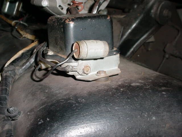
Here are some shots of the connections on my 60. The braided ground is attached to the VR using the small screw that attaches the VR Cover to the base. After polarization, this has been working fine on my car.
Hope you get this thing tracked down.
Dave Z
Here are some shots of the connections on my 60. The braided ground is attached to the VR using the small screw that attaches the VR Cover to the base. After polarization, this has been working fine on my car.
Hope you get this thing tracked down.
Dave Z
09-10-2010, 09:14 PM
#34
Drifting
Do you have an assembly manual for the car ??? The section dealing with the electrical system should show how this ground wire is attached. On my 67, the regulator is mounted using rubber isolators also, but it is grounded by a wire with a loop, and there is a small hole drilled in the base of the regulator. The loop is held against the regulator base by a bolt that goes through that hole. Is there a small hole in your regulator base ???? I took a picture for you. You can see the wire with the loop and the bolt that holds both the capacitor and the ground wire onto the regulator. Even though my setup is a later car with an alternator, yours should be similar.
RON
09-10-2010, 09:23 PM
#35
Drifting
Look at DZ's picture closely. There is a hole in the regulator base about 1 inch to the right of where he has his braid grounded to his regulator. Is it possible that is where it gets connected ??? Similar setup to later cars with alternators.
RON
09-10-2010, 09:44 PM
#36
Burning Brakes
Member Since: Jun 2006
Location: Hudson North Carolina
Posts: 765
Likes: 0
Received 2 Likes
on
2 Posts
Isnake is right mine attaches to the front cover screw along with another ground....probably for the head lights or park lights

The other end attaches to the gen with the bolt that holds the capacitor

The other end attaches to the gen with the bolt that holds the capacitor
09-10-2010, 09:52 PM
#37
Drifting
Thread Starter
Well HOT DAMN!
I ran a ground wire straight from the ground connection on the generator to the base of the regulator and it charging like a champ! 13.5-14v at the battery now even at low idle at full engine temp! Quick question, how volts is too much to the battery? I want to test a higher RPM to be sure it's not over charging the battery.
Ok, I've looked at the pictures, thank you guys VERY much BTW, and I see now what I have to do. What was throwing me off is this is exactly how it was wired when I bought the car and I didn't even catch it taking it apart or putting it back together! Plus the ground eyelet at the VR has an inside diameter almost the size of the head of the screw that holds the cover on lol. Plus the 54 year old paint on the VR doesn't look work there. Hmmm. I'll have to find a washer and do it. 56Heap, that picture is perfect! 1 funny thing though, I don't seem to have that small extra ground anywhere, maybe it a ground for radio only cars that mine is missing since I'm a no radio car.
Thanks a million guys!!!!!!!! Once I get my shifter linkage sorted out, I'll be able to drive the car down the street under it's own power for the first time in almost 28 years!!!!!!!
09-10-2010, 10:04 PM
#39
Drifting
Thread Starter
Oh ok. Yes, all works. I even fixed my brake lights the other day. Only lights that don't work now are the dash backlights. I'm going to check the fuse on the back of the switch.
09-11-2010, 08:22 PM
#40
Team Owner
Member Since: Oct 2000
Location: Washington Michigan
Posts: 38,899
Received 1,857 Likes
on
1,100 Posts
The attachment of that braided ground shield under a voltage regulator cover screw is shown in your Assembly Manual - section 12, sheet 6.00, View "E", where it says "ground".
Doesn't matter what year pre-'69 Corvette you have - if the voltage regulator base isn't grounded directly to the generator or alternator, the regulator won't work.
Doesn't matter what year pre-'69 Corvette you have - if the voltage regulator base isn't grounded directly to the generator or alternator, the regulator won't work.