How To - Step by Step A/C Compressor Front Seal Replacement
 06-26-2011, 01:36 PM
#1
Tech Contributor

Thread Starter

Greetings,
The A6 A/C compressor in my 65 was rebuilt by Classic Auto Air in October 2006, but by May 2008 was still slinging oil out of the front seal, and also losing Freon. I put off repairing the compressor until I had the tools needed to recover the R-12 from my system.
This weekend I successfully replaced the front seal and having learned a few nuances of the process I wanted to share what I've found in an end-to-end how-to. I'll distribute the info into 3 posts within the same thread, simply to break up the discussion into Seal Removal, Seal Installation, A/C Recharging segments.
First things first: Big kudos to Mechron and Powershift for educating me in 2008 when I first started having issues with my rebuilt compressor. Most things I document here with regard to evacuating the system, using the gauges, and recharging the system, came from them.
http://forums.corvetteforum.com/c1-a...questions.html
Also, kudos to jprop for starting a thread on his own front seal replacement, which is what inspired me to try this repair myself instead of sending the compressor back to Classic Auto Air.
http://forums.corvetteforum.com/c1-a...ompressor.html
I bought my tools and seals from www.ackits.com. I have no affiliation with them other than the part numbers I quote will be the part numbers they, or their supplier use.
Removing the seal
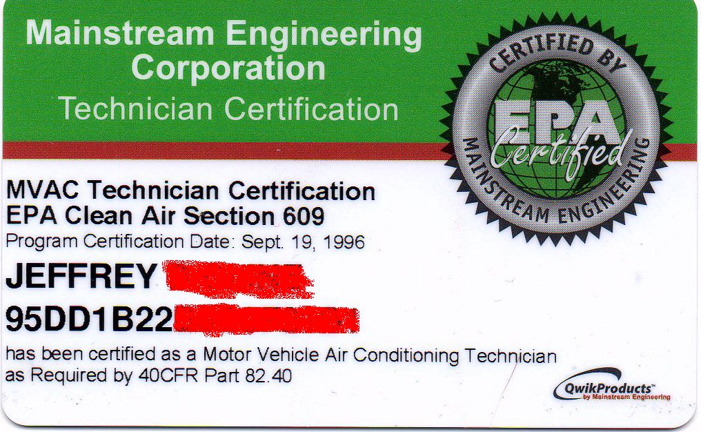
First, since we are working with R-12, let's get legal.
http://www.epatest.com/609/ + $19.95 and about 2 hours of time gets me certified:
Next I need to evacuate the R-12 from my 65. My Robinair 17400 Recovery/Recycling machine will do the trick while complying with the law.
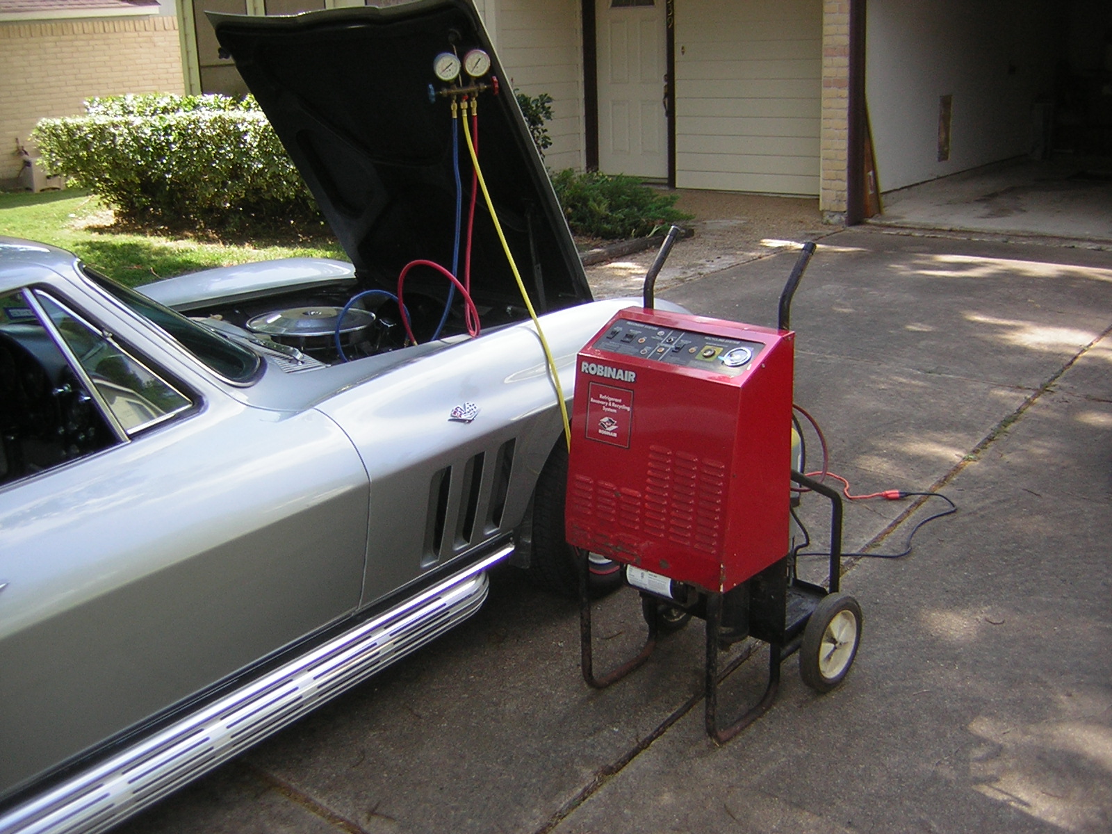
Using the Robinair
I recovered R-12 until the high and low pressure gauges showed approximately 0 psi at rest.
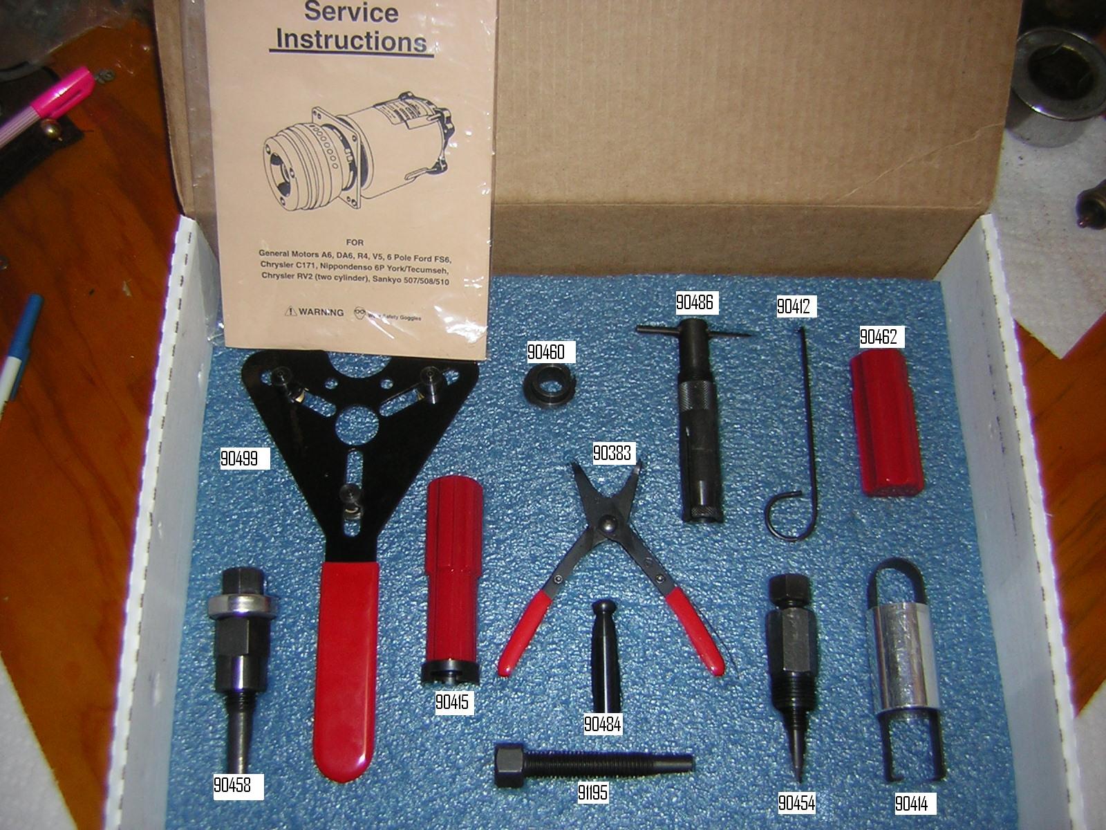
Now for some tools. This Mastercool 91269 kit from www.ackits.com has almost everything I need (but for snap ring pliers that fit!). The Mastercool part numbers for each tool appear in this image. I'll be referencing those numbers in this thread and most of the tools pictured will be used.
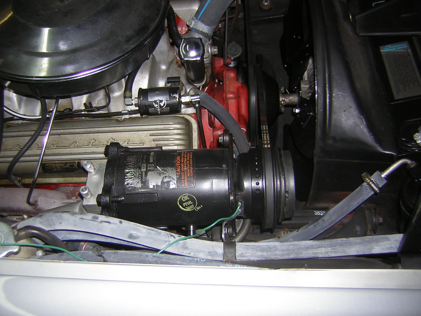
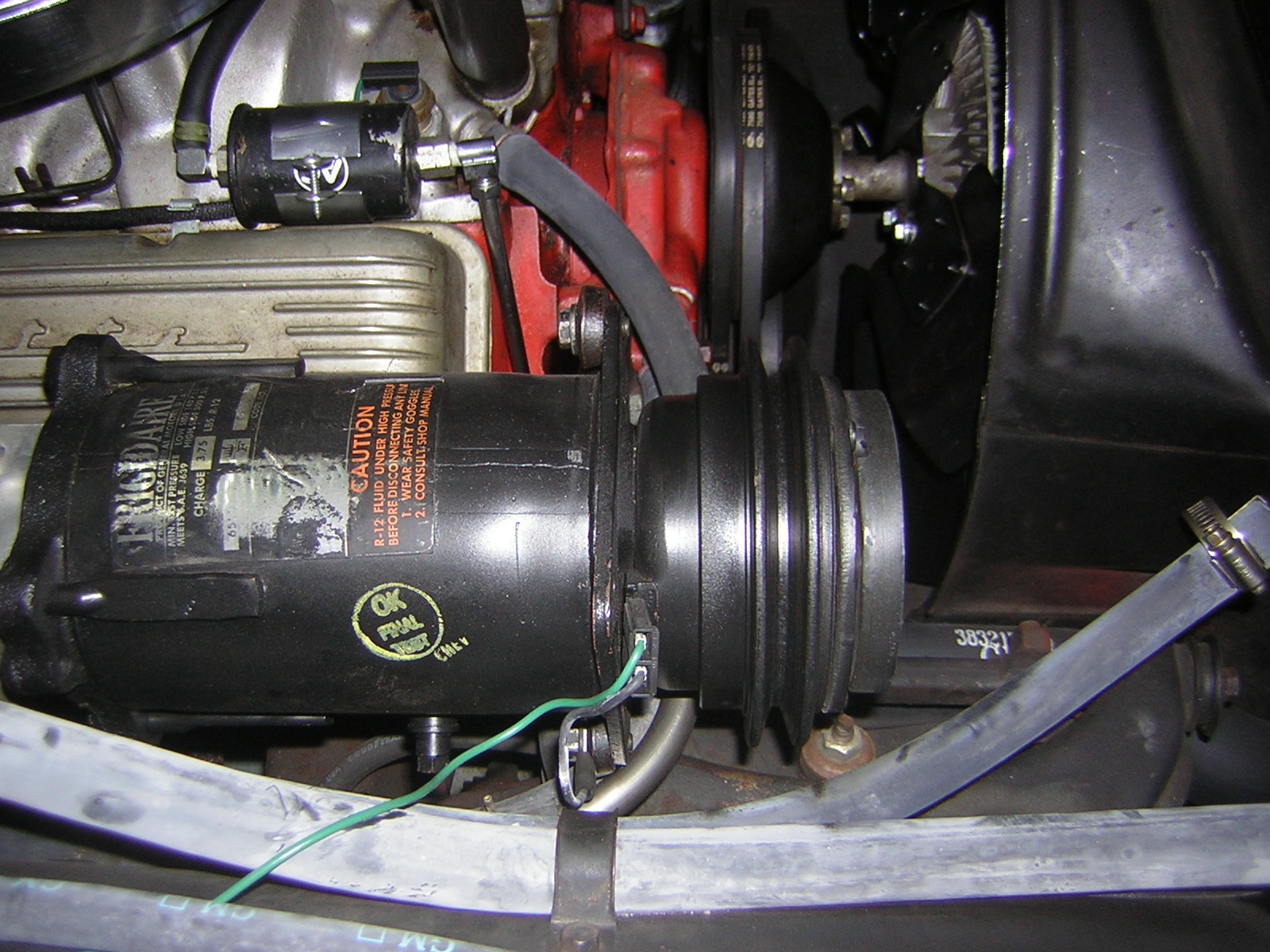
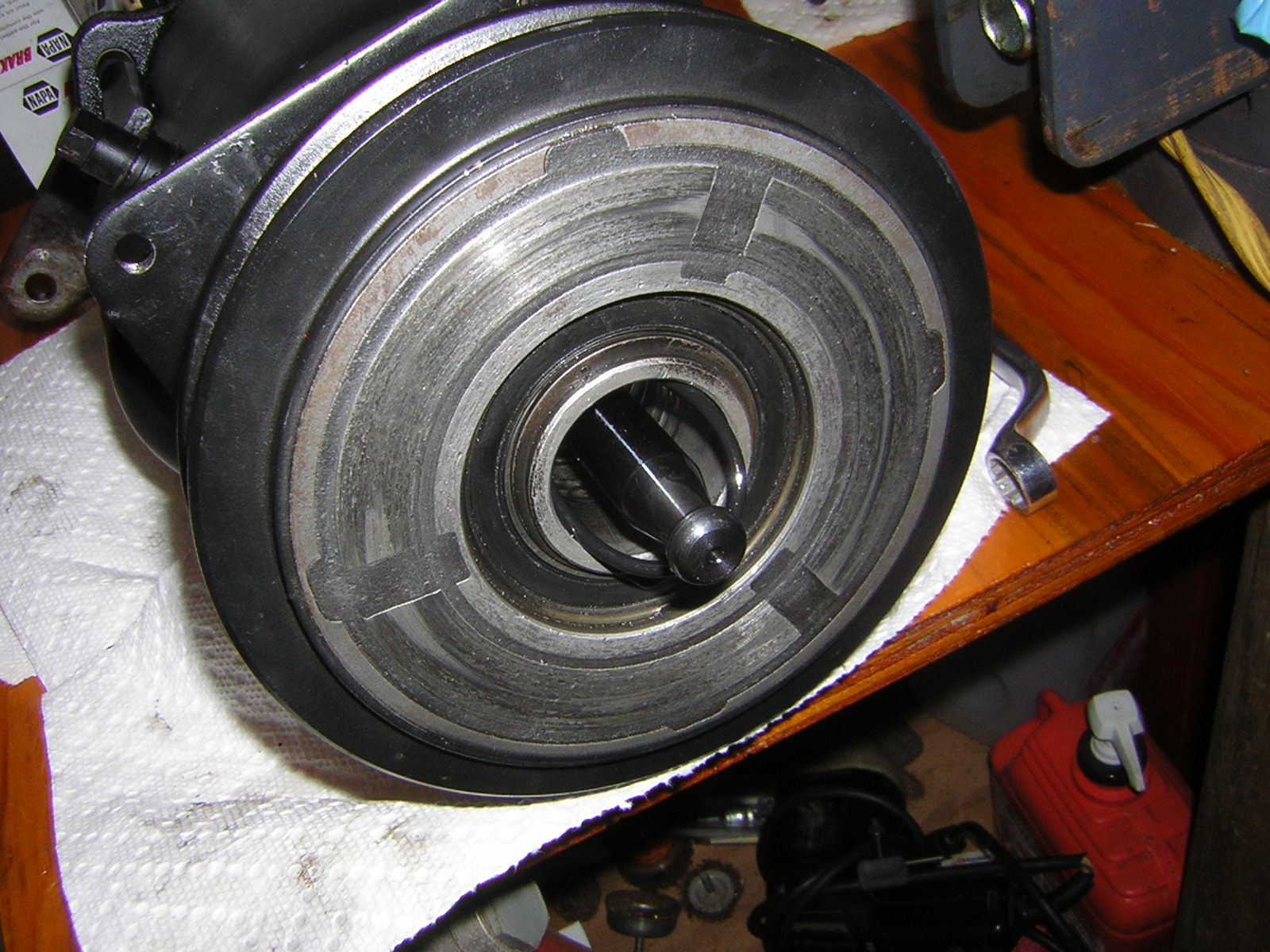
After moving the car into my workshop, it's time to get busy. Here's the offender. A late 1965 A6 compressor:
Get the belt off:
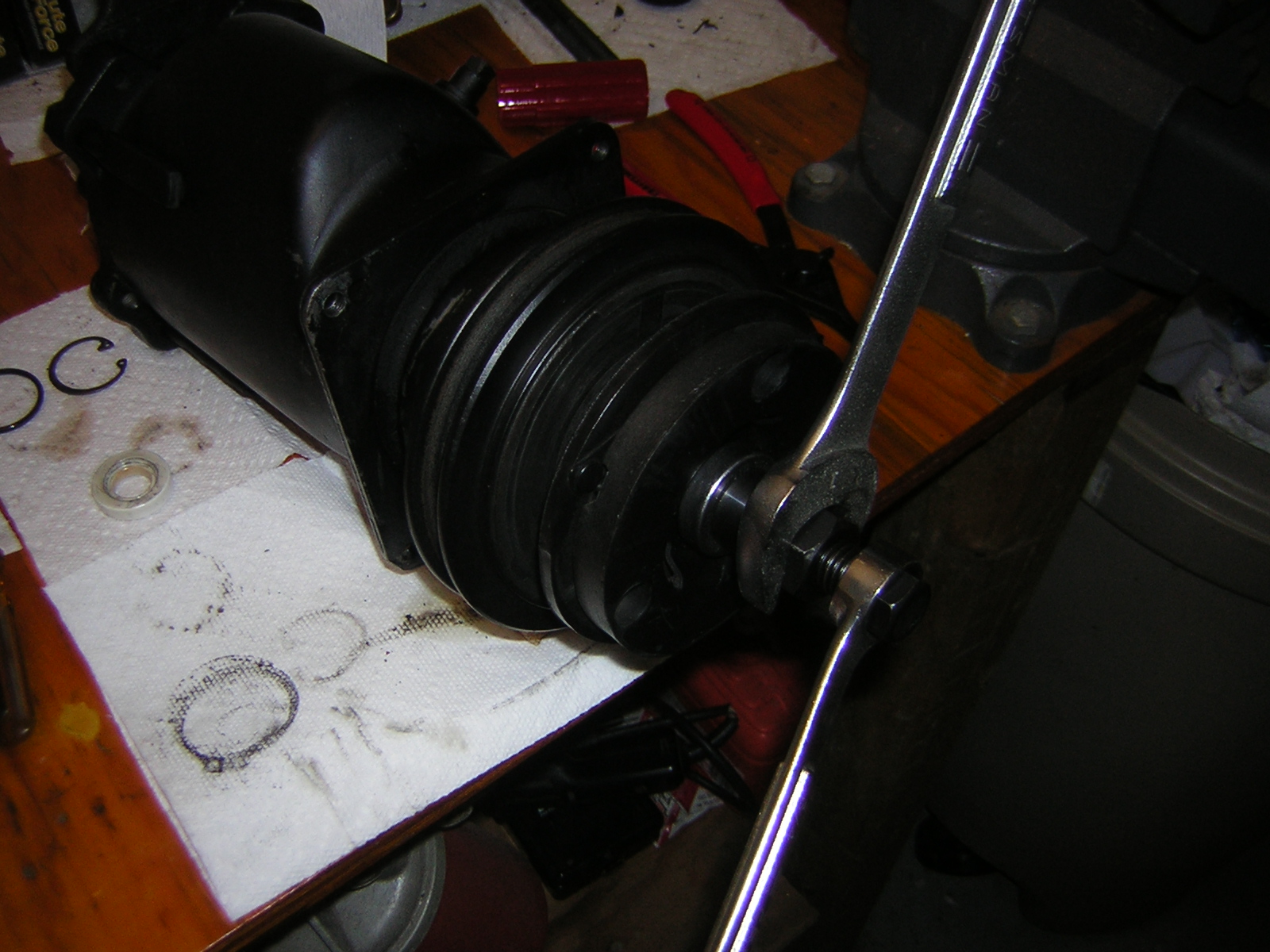
Then grab the Mastercool 90499 spanner wrench to hold the clutch hub.
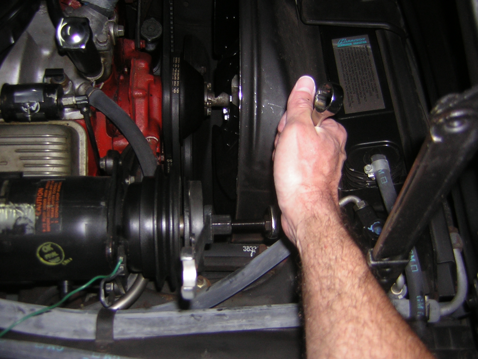
Now with a 9/16" socket, remove the center hub nut:
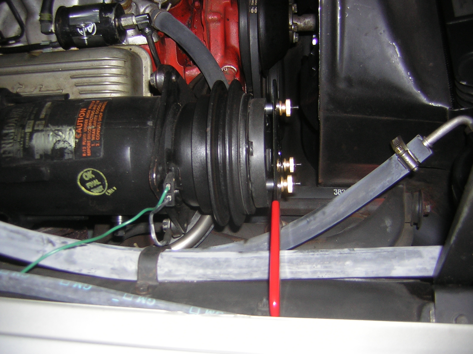
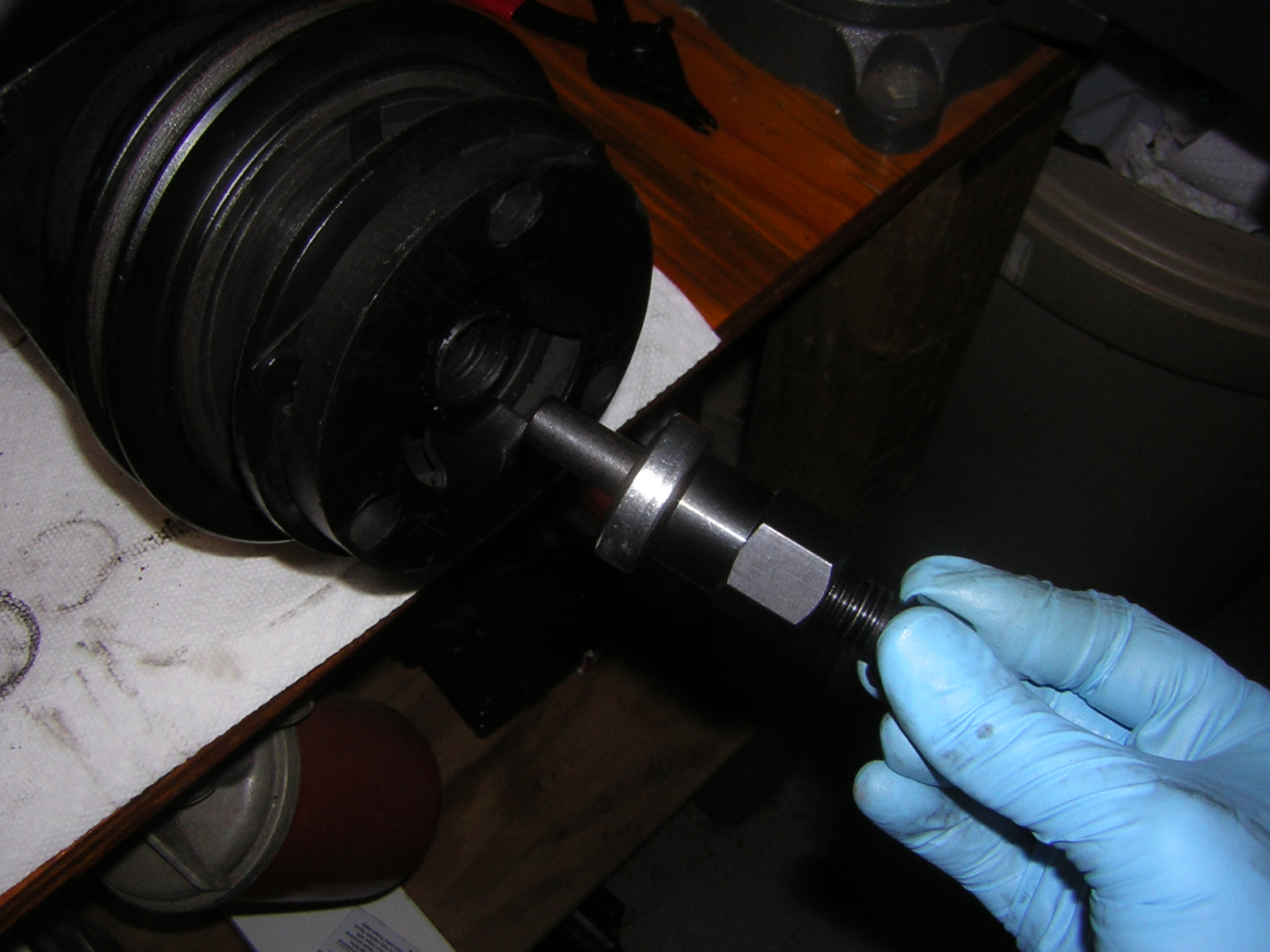
Thread the Mastercool 90454 clutch hub removal tool into the clutch hub:
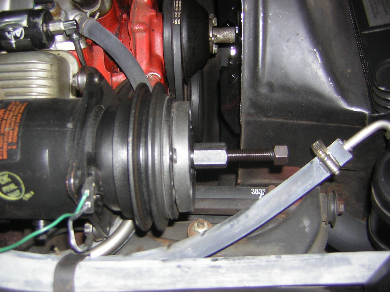
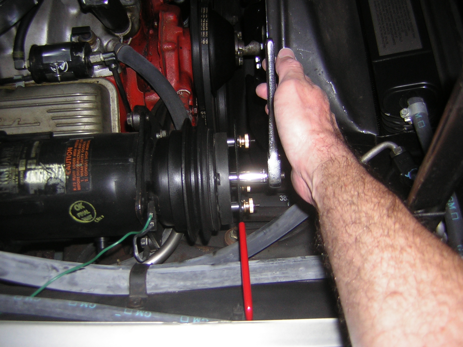
and then with 3/4" and 7/8" wrenches, remove the hub:
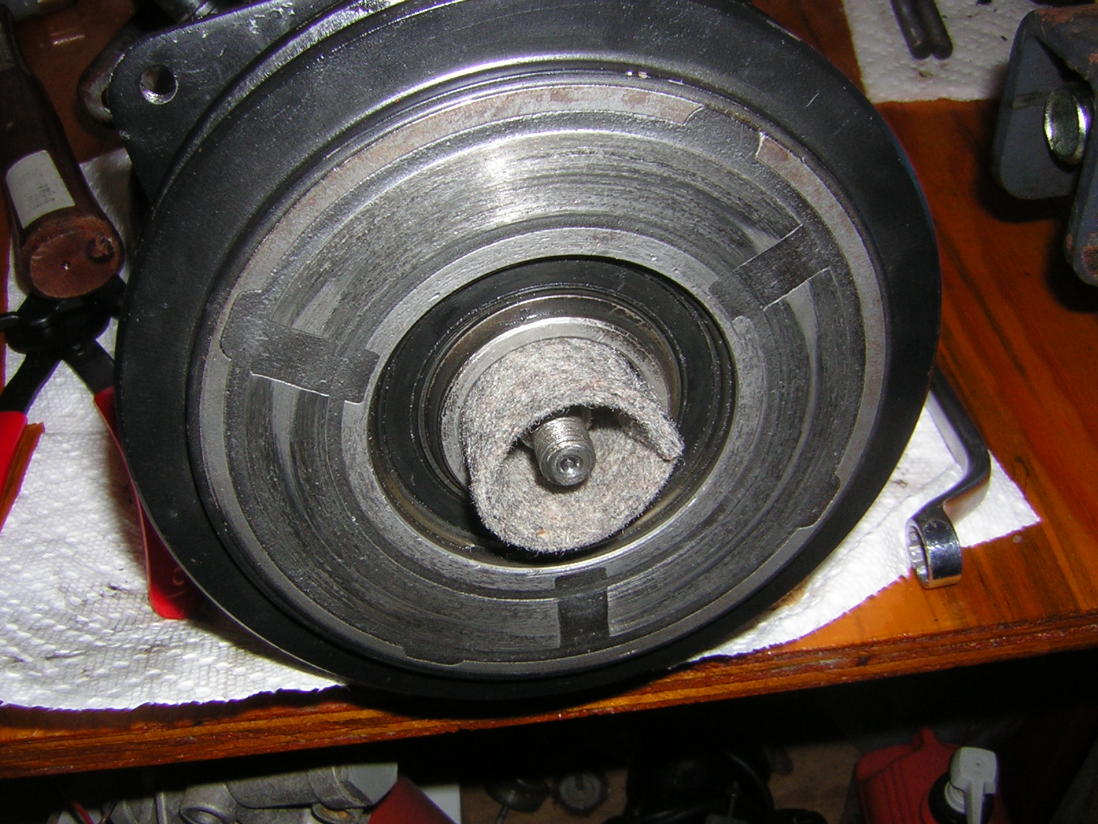
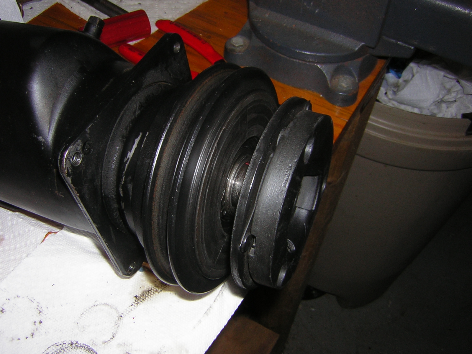
Clutch hub is off and the black felt oil wick is visible:
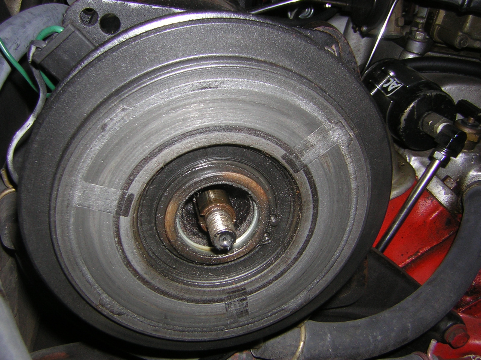
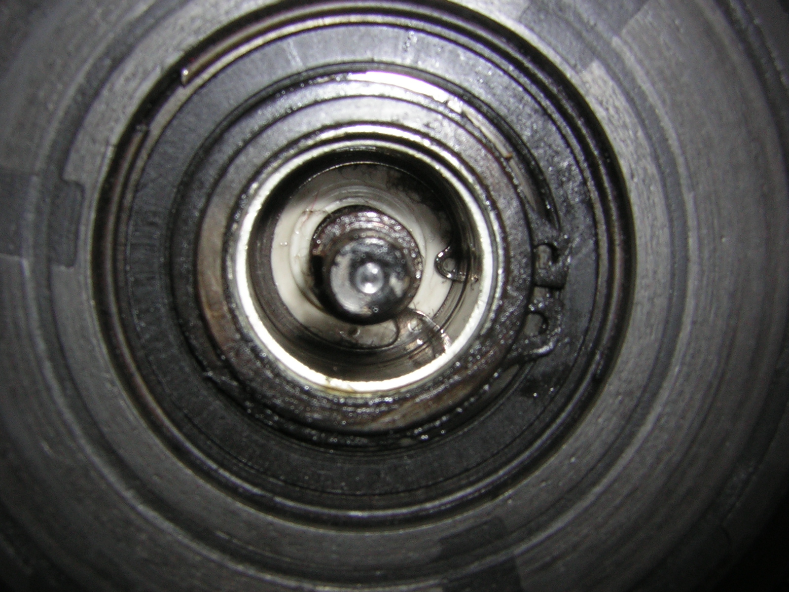
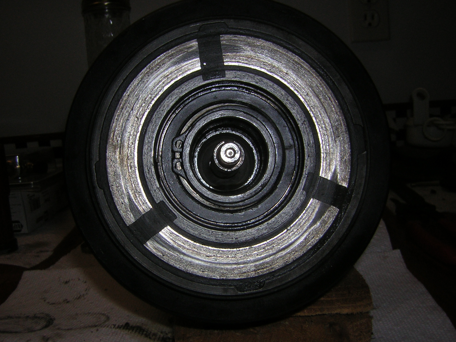
After removing the oil wick, the snap ring is visible:
At this point it became obvious that I could not effectively work on the compressor with it installed on the car. Too hard to see the snap ring. So, off the compressor comes.
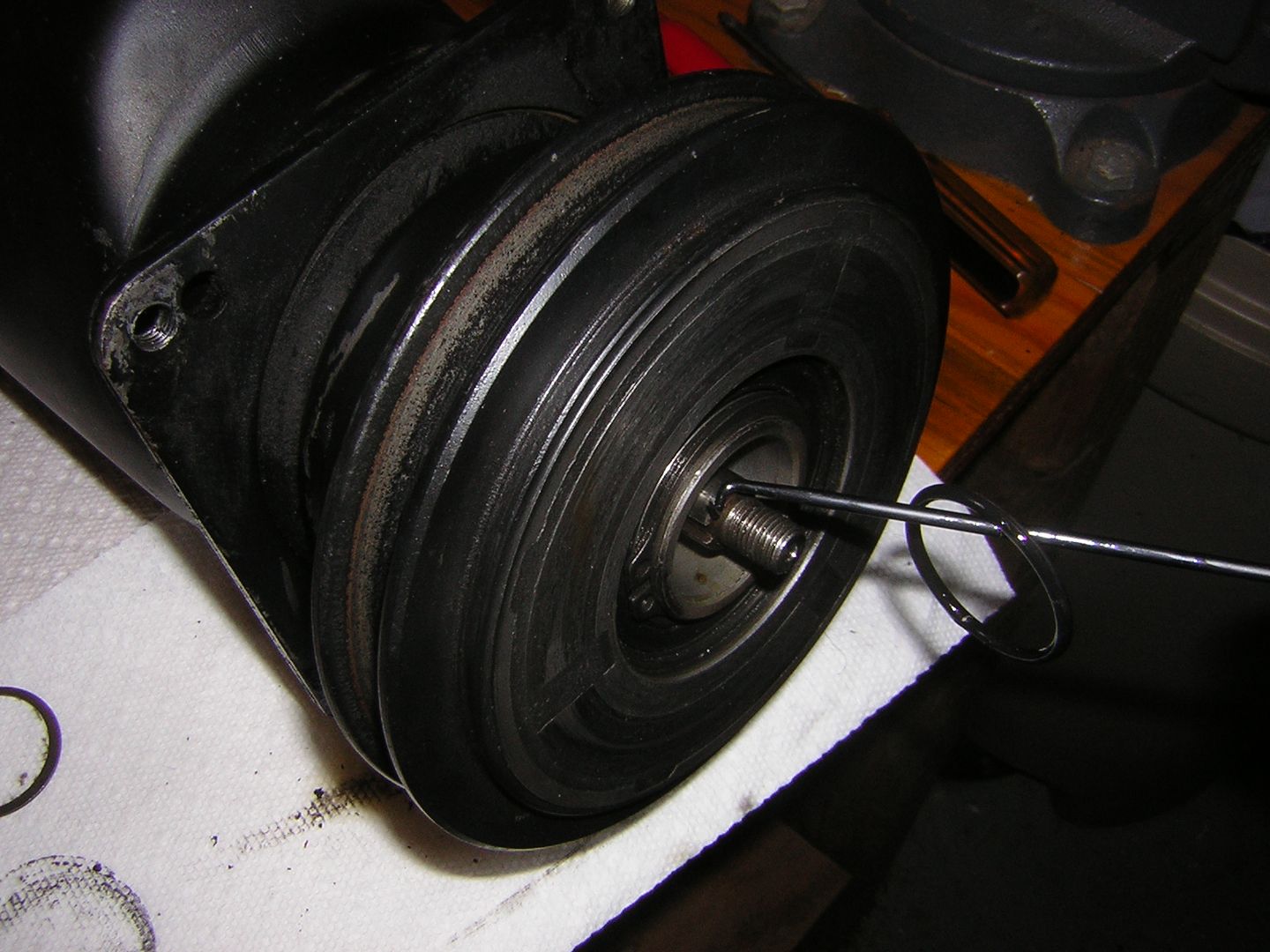
Removing the snap ring required a set of picks, because all of the snap ring pliers I purchased this day, were too short to reach.
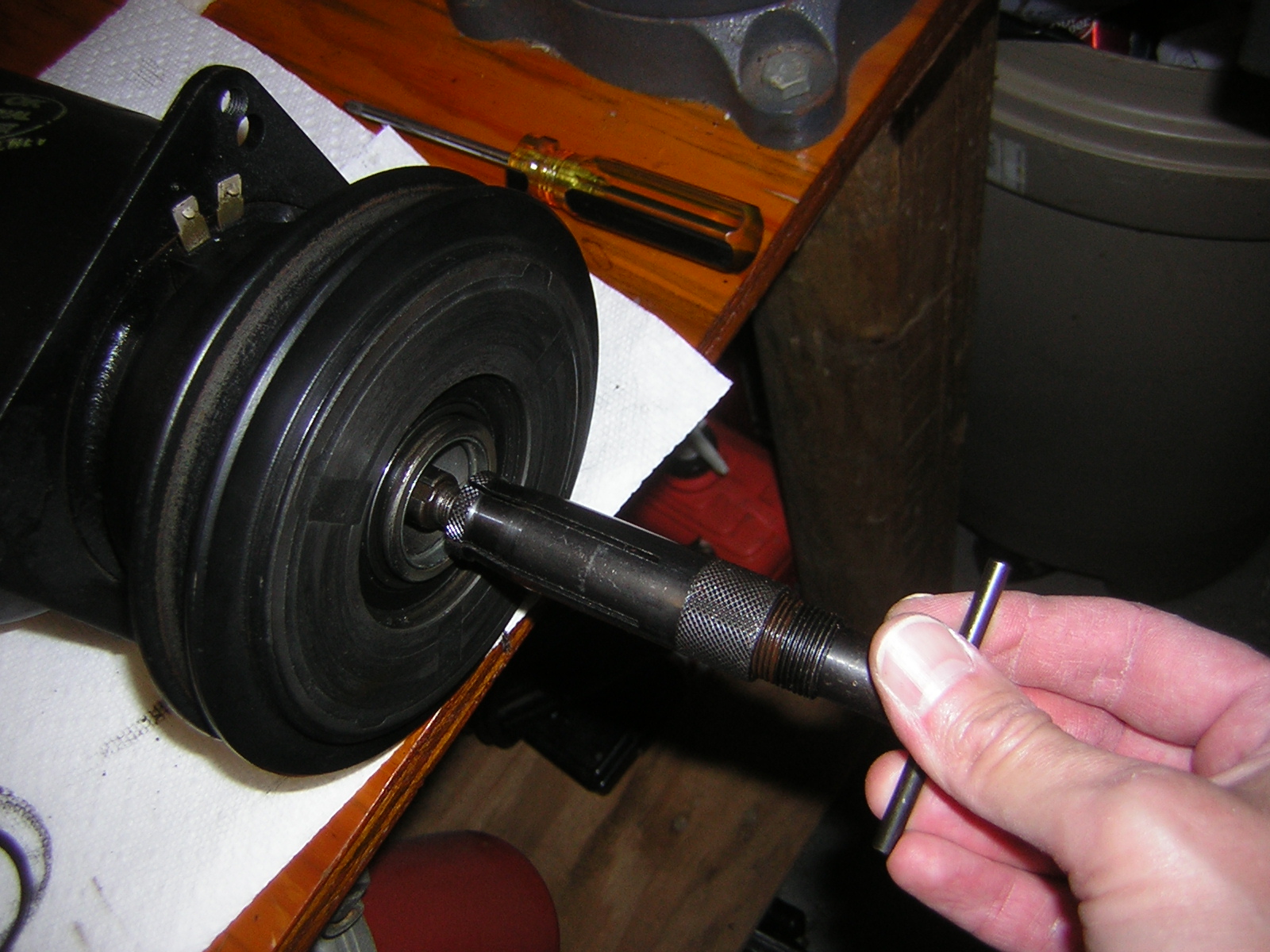
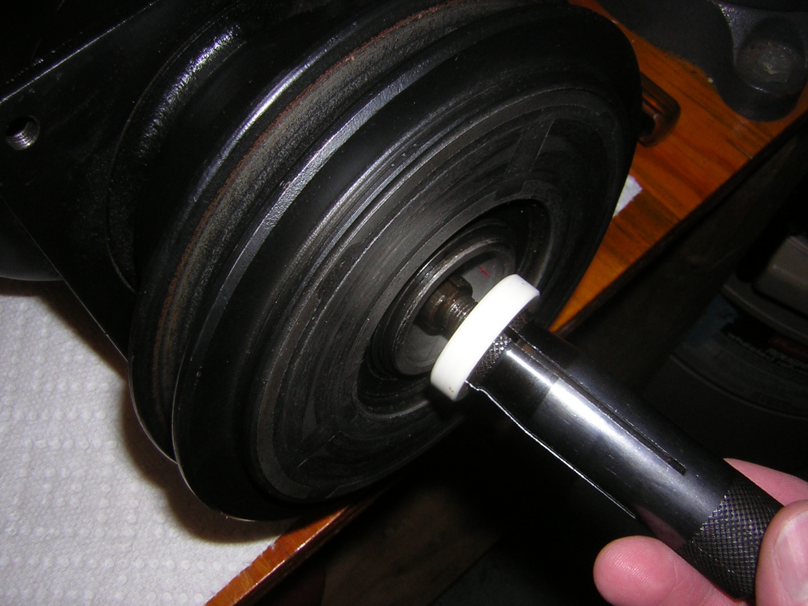
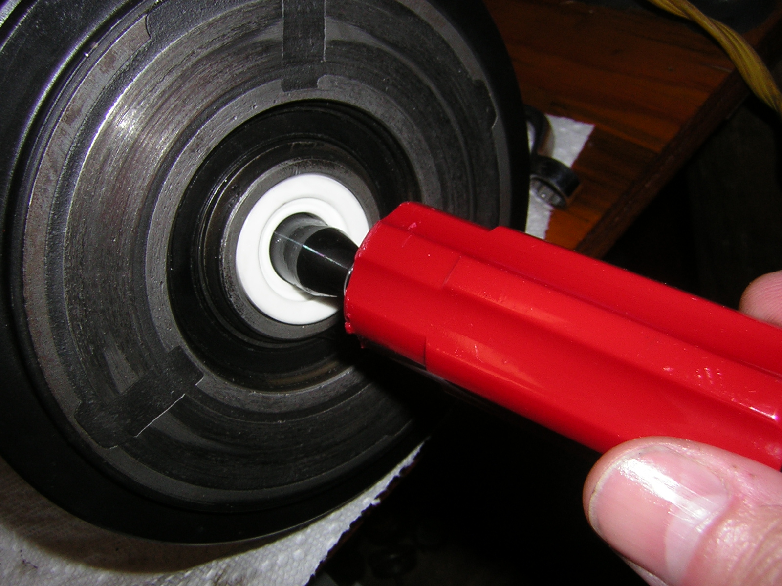
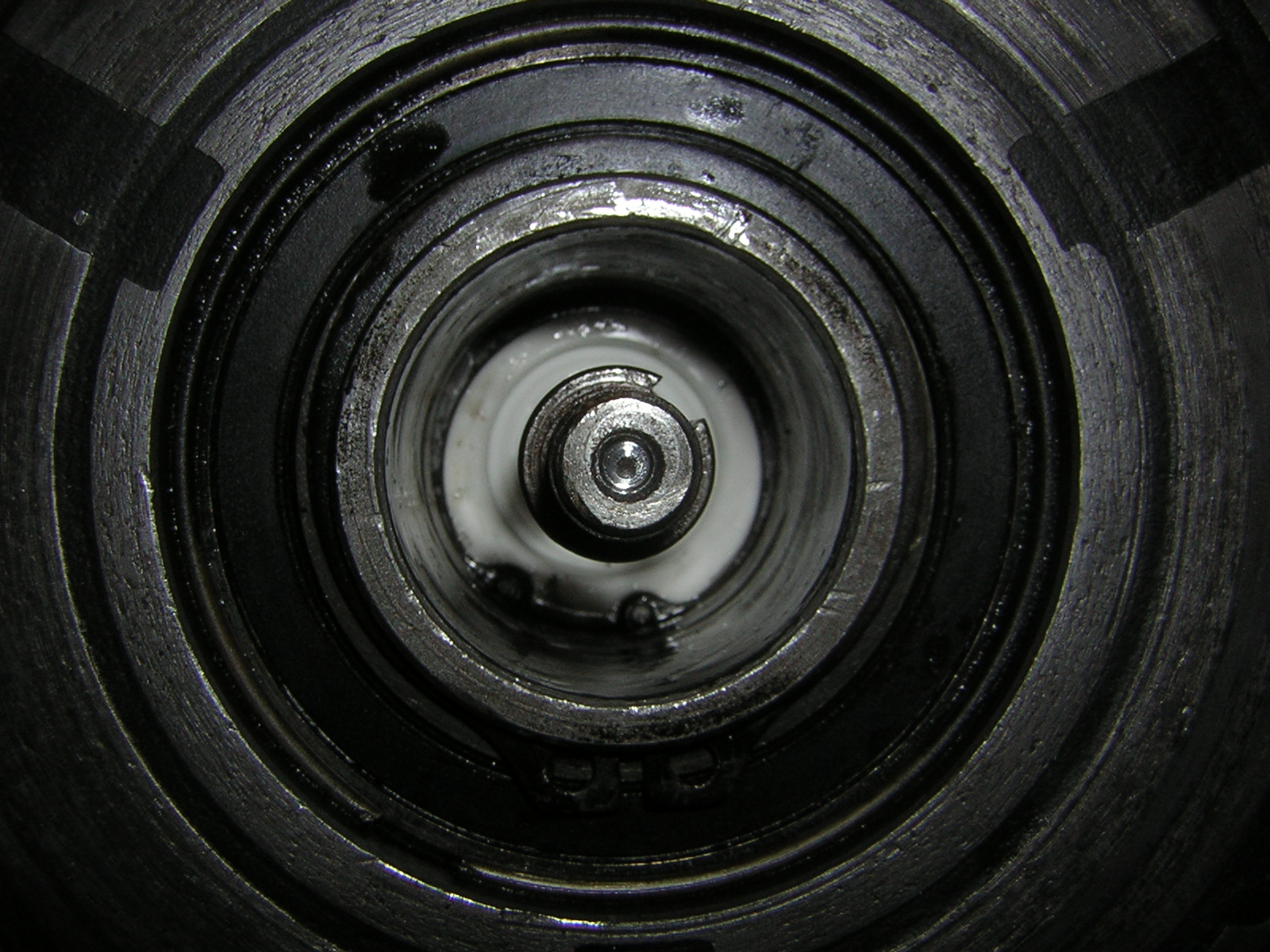
With the snap ring removed, use Mastercool 90486 seal seat installer/remover to access and remove the ceramic seal seat. Install the tool until it mates with the seal seat, then turn the handle clockwise to screw the handle into the tool shaft, expanding the tool shaft against the inner edge of the seal seat, grabbing the seal seat. Remove the seal seat:
Your compressor may, or may not, have a thin metal ring pressed into the front of the compressor opening, which serves (as near as I can tell) to help retain the big felt wick. If yours has this ring, remove it by just prying it out. I learned this on my first of three seal replacement attempts when pulling the old ceramic seal seat out caught on the metal ring.
Use Mastercool 90412 O-ring remover to access and remove the O-ring (or a pick will do):
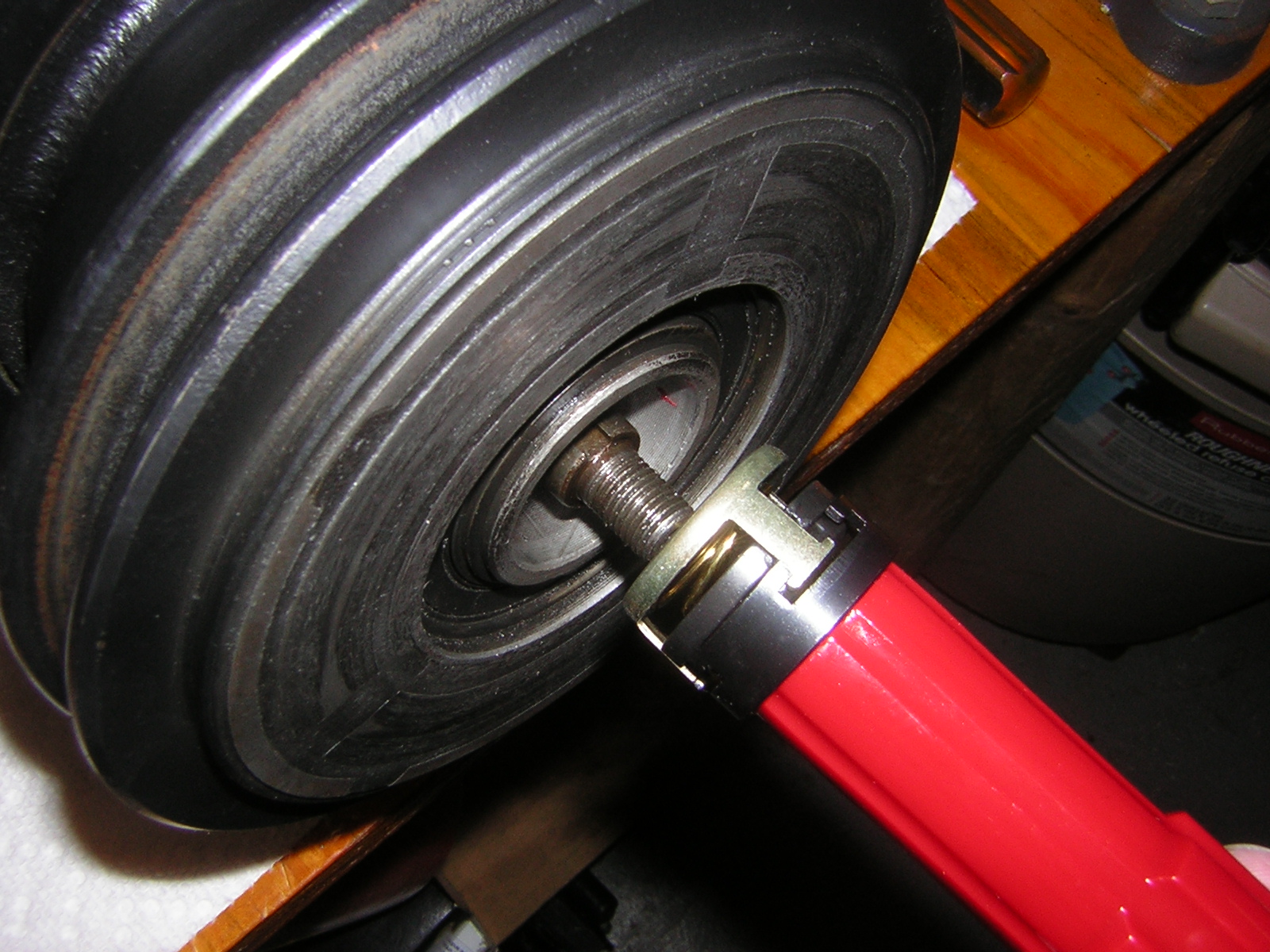
Use Mastercool 90415 ceramic seal cage installer/remover to remove the ceramic seal cage. Push the tool into the cage against the spring tension and turn the tool to the right to latch onto the cage. Then withdraw the cage:
Now we are ready to install the seal.
The A6 A/C compressor in my 65 was rebuilt by Classic Auto Air in October 2006, but by May 2008 was still slinging oil out of the front seal, and also losing Freon. I put off repairing the compressor until I had the tools needed to recover the R-12 from my system.
This weekend I successfully replaced the front seal and having learned a few nuances of the process I wanted to share what I've found in an end-to-end how-to. I'll distribute the info into 3 posts within the same thread, simply to break up the discussion into Seal Removal, Seal Installation, A/C Recharging segments.
First things first: Big kudos to Mechron and Powershift for educating me in 2008 when I first started having issues with my rebuilt compressor. Most things I document here with regard to evacuating the system, using the gauges, and recharging the system, came from them.
http://forums.corvetteforum.com/c1-a...questions.html
Also, kudos to jprop for starting a thread on his own front seal replacement, which is what inspired me to try this repair myself instead of sending the compressor back to Classic Auto Air.
http://forums.corvetteforum.com/c1-a...ompressor.html
I bought my tools and seals from www.ackits.com. I have no affiliation with them other than the part numbers I quote will be the part numbers they, or their supplier use.
Removing the seal
First, since we are working with R-12, let's get legal.
http://www.epatest.com/609/ + $19.95 and about 2 hours of time gets me certified:
Next I need to evacuate the R-12 from my 65. My Robinair 17400 Recovery/Recycling machine will do the trick while complying with the law.
Using the Robinair
- Start car and run A/C for a few moments
- Shut off A/C and car
- Connect an A/C gauge set to the compressor manifold
- Connect the blue hose to the low pressure side (comes from firewall)
- Connect red hose to the high pressure side (goes to front of car)
- Connect yellow hose to the inlet port of the Robinair
- Open both valves on the gauge set
- Open both valves on the recovery tank on the Robinair
- Turn on MAIN POWER on the Robinair
- Turn on RECOVERY START on Robinair
- Press the START switch on the Robinair to begin evacuating the R-12 from the car
- Recovery machine will operate until R-12 has been recovered from the car or until recovery tank is full
- Open Accumulator Pressure Valve on the back of Robinair for 15 seconds then close. This returns compressor oil to the Robinair compressor
- Slowly open the Oil Drain Valve on the back of the Robinair to deposit oil collected from the car's A/C system, into a catch bottle. Close the valve before the system fully depressurizes
- Measure the oil collected in the catch bottle - this is the amount of new oil that should be reintroduced into the A/C system before charging.
- Turn off MAIN POWER
- Disconnect A/C gauge set from compressor manifold.
I recovered R-12 until the high and low pressure gauges showed approximately 0 psi at rest.
Now for some tools. This Mastercool 91269 kit from www.ackits.com has almost everything I need (but for snap ring pliers that fit!). The Mastercool part numbers for each tool appear in this image. I'll be referencing those numbers in this thread and most of the tools pictured will be used.
After moving the car into my workshop, it's time to get busy. Here's the offender. A late 1965 A6 compressor:
Get the belt off:
Then grab the Mastercool 90499 spanner wrench to hold the clutch hub.
Now with a 9/16" socket, remove the center hub nut:
Thread the Mastercool 90454 clutch hub removal tool into the clutch hub:
and then with 3/4" and 7/8" wrenches, remove the hub:
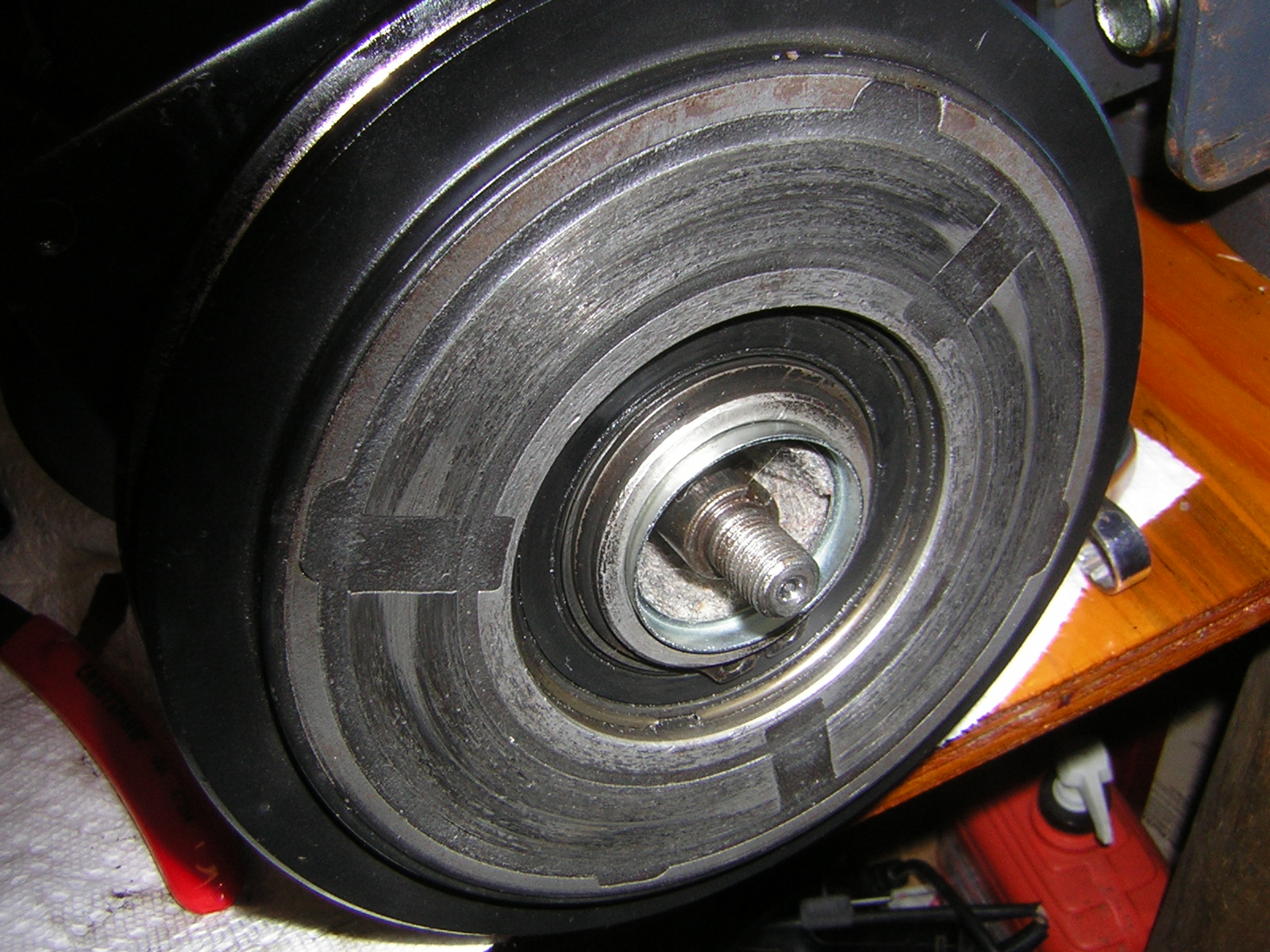
Clutch hub is off and the black felt oil wick is visible:
After removing the oil wick, the snap ring is visible:
At this point it became obvious that I could not effectively work on the compressor with it installed on the car. Too hard to see the snap ring. So, off the compressor comes.
Removing the snap ring required a set of picks, because all of the snap ring pliers I purchased this day, were too short to reach.
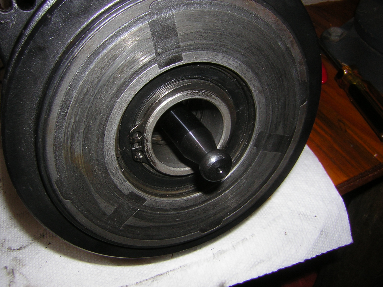
With the snap ring removed, use Mastercool 90486 seal seat installer/remover to access and remove the ceramic seal seat. Install the tool until it mates with the seal seat, then turn the handle clockwise to screw the handle into the tool shaft, expanding the tool shaft against the inner edge of the seal seat, grabbing the seal seat. Remove the seal seat:
Your compressor may, or may not, have a thin metal ring pressed into the front of the compressor opening, which serves (as near as I can tell) to help retain the big felt wick. If yours has this ring, remove it by just prying it out. I learned this on my first of three seal replacement attempts when pulling the old ceramic seal seat out caught on the metal ring.
Use Mastercool 90412 O-ring remover to access and remove the O-ring (or a pick will do):
Use Mastercool 90415 ceramic seal cage installer/remover to remove the ceramic seal cage. Push the tool into the cage against the spring tension and turn the tool to the right to latch onto the cage. Then withdraw the cage:
Now we are ready to install the seal.
Last edited by 62Jeff; 08-28-2011 at 03:22 PM. Reason: Added detailed steps for using Robinair
 06-26-2011, 01:37 PM
#2
Tech Contributor
Thread Starter
Installing the Seal and Assemble Compressor
Clean the void in the compressor left by removal of the seal components:
Then install Mastercool 90484 seal protector to prevent the O-ring and seal from getting nicked:
If you wish to try your luck with new technology, using Double-lip seal 21-34659 eliminates the multi-part seal cage and ceramic seal component. You can see when this photo was taken I'd already failed with 21-34734.
NOTE 1: If your compressor shaft is approximately 13-14mm in diameter you need seal 21-34659, if the shaft is larger, you need seal 21-34734.
NOTE 2: www.ACKits.com’s website currently shows kit 21-34659 with multiple O-rings and felt wicks, however the kit as shipped comes with a single O-ring and no felt wick.
Here are all 3 seal options - original style ceramic, plus small and big double-lip seal
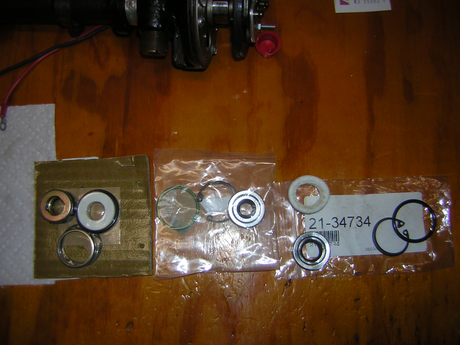
I'm using Ceramic seal 21-34608 assembly as original, because I tried unsuccessfully to use the two different double-lip seals. Coat the seal assembly with mineral oil (since I'm going back with R-12, otherwise a different oil is required).
Use Mastercool 90415 ceramic seal seat installer/remover to install the ceramic seal cage. Push the seal cage in place and turn until the flats on the seal engage the flats of the shaft. The first photo shows the back of the seal cage assembly, and the 2 flat inner edges.
Install the O-ring after first coating it in mineral oil:
Coat the ceramic seal seat with mineral oil and then insert the ceramic seal seat into the snout of the compressor and use Mastercool 90462 seal seat installer to push it all the way in until it seats on the O-ring.
Install the snap ring making sure it seats in the snap ring groove. The snap ring will have a completely flat side, and a side with a beveled edge. Put the flat side of the snap ring up against the seal seat.
Install the felt oil wick:
followed by the metal retaining ring.
Attach the clutch hub to the compressor shaft making sure to align the woodruff key:
Install Mastercool 90458 clutch hub installer tool by threading the center of the tool onto the compressor shaft:
And using 3/4" and 1" wrenches install the hub by tightening the outer tool nut while holding the center of the tool static:
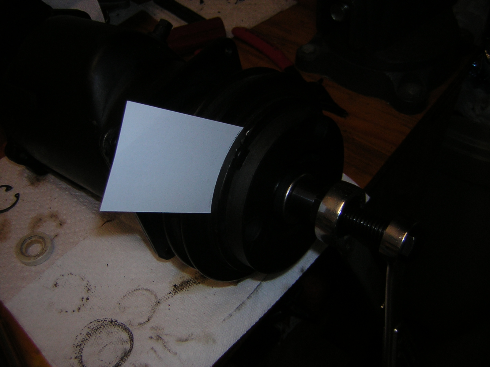
Tighten the hub until a business card enters the air gap with just a little friction (or until you have 3/32" clearance):
Finally, install the special flat washer on the compressor shaft, followed by the hub nut. The hub nut has a flat side, which goes against the flat washer. Using the Mastercool 90499 spanner wrench and a 9/16" socket, tighten the hub nut to 14-18 lbs-ft:
Now we are ready to evacuate and charge the system.
Clean the void in the compressor left by removal of the seal components:
Then install Mastercool 90484 seal protector to prevent the O-ring and seal from getting nicked:
If you wish to try your luck with new technology, using Double-lip seal 21-34659 eliminates the multi-part seal cage and ceramic seal component. You can see when this photo was taken I'd already failed with 21-34734.
NOTE 1: If your compressor shaft is approximately 13-14mm in diameter you need seal 21-34659, if the shaft is larger, you need seal 21-34734.
NOTE 2: www.ACKits.com’s website currently shows kit 21-34659 with multiple O-rings and felt wicks, however the kit as shipped comes with a single O-ring and no felt wick.
Here are all 3 seal options - original style ceramic, plus small and big double-lip seal
I'm using Ceramic seal 21-34608 assembly as original, because I tried unsuccessfully to use the two different double-lip seals. Coat the seal assembly with mineral oil (since I'm going back with R-12, otherwise a different oil is required).
Use Mastercool 90415 ceramic seal seat installer/remover to install the ceramic seal cage. Push the seal cage in place and turn until the flats on the seal engage the flats of the shaft. The first photo shows the back of the seal cage assembly, and the 2 flat inner edges.
Install the O-ring after first coating it in mineral oil:
Coat the ceramic seal seat with mineral oil and then insert the ceramic seal seat into the snout of the compressor and use Mastercool 90462 seal seat installer to push it all the way in until it seats on the O-ring.
Install the snap ring making sure it seats in the snap ring groove. The snap ring will have a completely flat side, and a side with a beveled edge. Put the flat side of the snap ring up against the seal seat.
Install the felt oil wick:
followed by the metal retaining ring.
Attach the clutch hub to the compressor shaft making sure to align the woodruff key:
Install Mastercool 90458 clutch hub installer tool by threading the center of the tool onto the compressor shaft:
And using 3/4" and 1" wrenches install the hub by tightening the outer tool nut while holding the center of the tool static:
Tighten the hub until a business card enters the air gap with just a little friction (or until you have 3/32" clearance):
Finally, install the special flat washer on the compressor shaft, followed by the hub nut. The hub nut has a flat side, which goes against the flat washer. Using the Mastercool 90499 spanner wrench and a 9/16" socket, tighten the hub nut to 14-18 lbs-ft:
Now we are ready to evacuate and charge the system.
Last edited by 62Jeff; 06-26-2011 at 02:07 PM.
06-26-2011, 01:37 PM
#3
Tech Contributor
Thread Starter
Evacuate and Charge the System
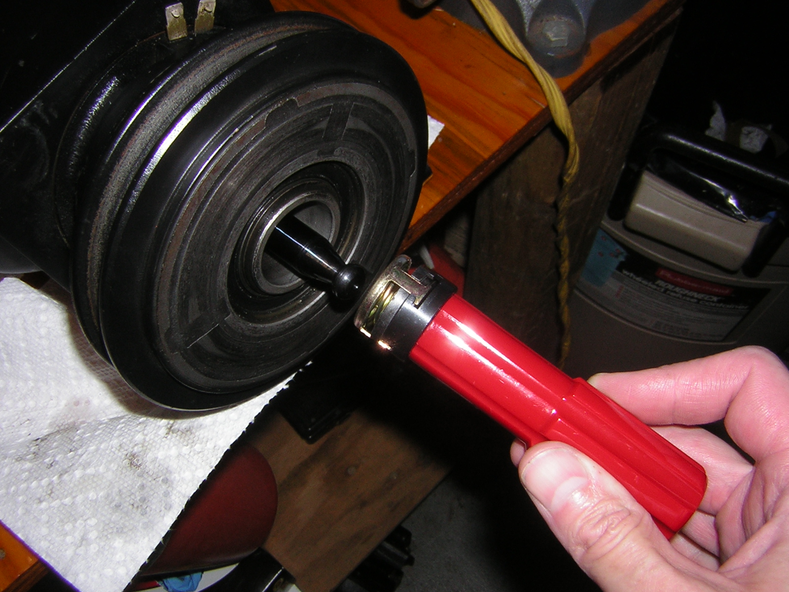
Now, before installing the compressor on the car, connect it to the A/C manifold and test for vacuum.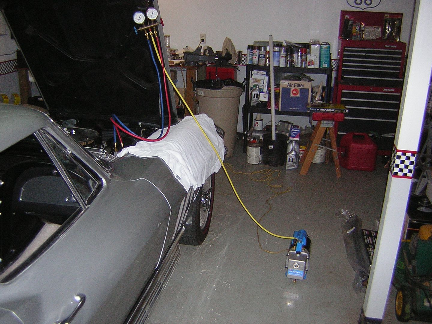
After getting a good vacuum that holds overnight, go ahead and bolt the compressor in place and prepare to charge the system.
Jeff
Now, before installing the compressor on the car, connect it to the A/C manifold and test for vacuum.
- Close both valves on the A/C gauge set
- Connect the blue hose to the low pressure side (comes from firewall)
- Connect red hose to the high pressure side (goes to front of car)
- Connect yellow hose to the vacuum pump
- Open both valves on the gauge set
- Turn on vacuum pump
- And observe low pressure gauge to confirm a vacuum is present. A vacuum of 28" or more (32" is max) is better, although this is dependent upon your altitude.
- After running the vacuum pump for an hour, close both valves on the gauge set and then turn off vacuum pump
- Monitor low pressure gauge and ensure the needle remains static for an extended period. I like to let it sit overnight to ensure the system doesn't have a slow leak.
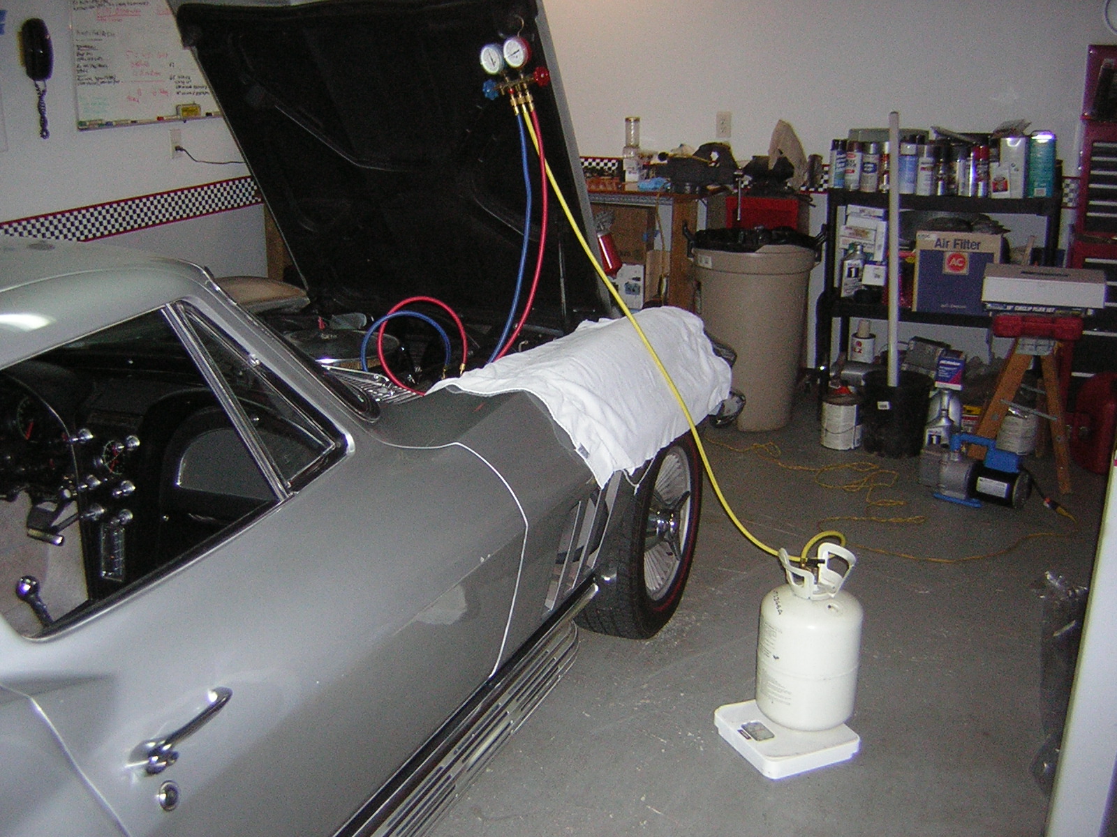
After getting a good vacuum that holds overnight, go ahead and bolt the compressor in place and prepare to charge the system.
- Move the yellow hose from the vacuum pump to the R-12 can.
- Open both valves on the gauge set
- Open the valve on the R-12 can to allow the vacuum present in the A/C system to pull R-12 from the R-12 can.
- After a few moments, close the high pressure valve on the gauge set
- Start car:
- Set idle to about 1,000 RPM
- ”AIR COND PULL” **** all the way out (A/C on)
- ”COOL IN-HOT PULL” **** all the way in (A/C temp on coolest)
- ”AIR PULL-FAN” **** all the way in (Vent doors on recirculate)
- ”AIR PULL-FAN” **** turned all the way to right (Fan on High)
- Windows rolled down
- Doors closed
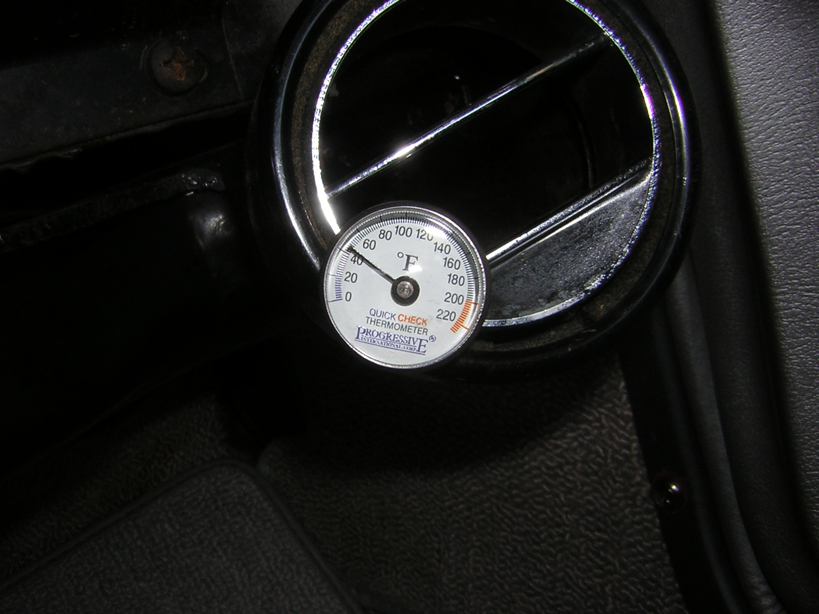
- Thermometer in right-side A/C vent.
- With car running, system will pull R-12 from can through the low pressure intake line
- Watch the bubble stream in sight glass while also watching gauges. A random bubble now and then is a safe target end point but no bubbles at all is optimal.
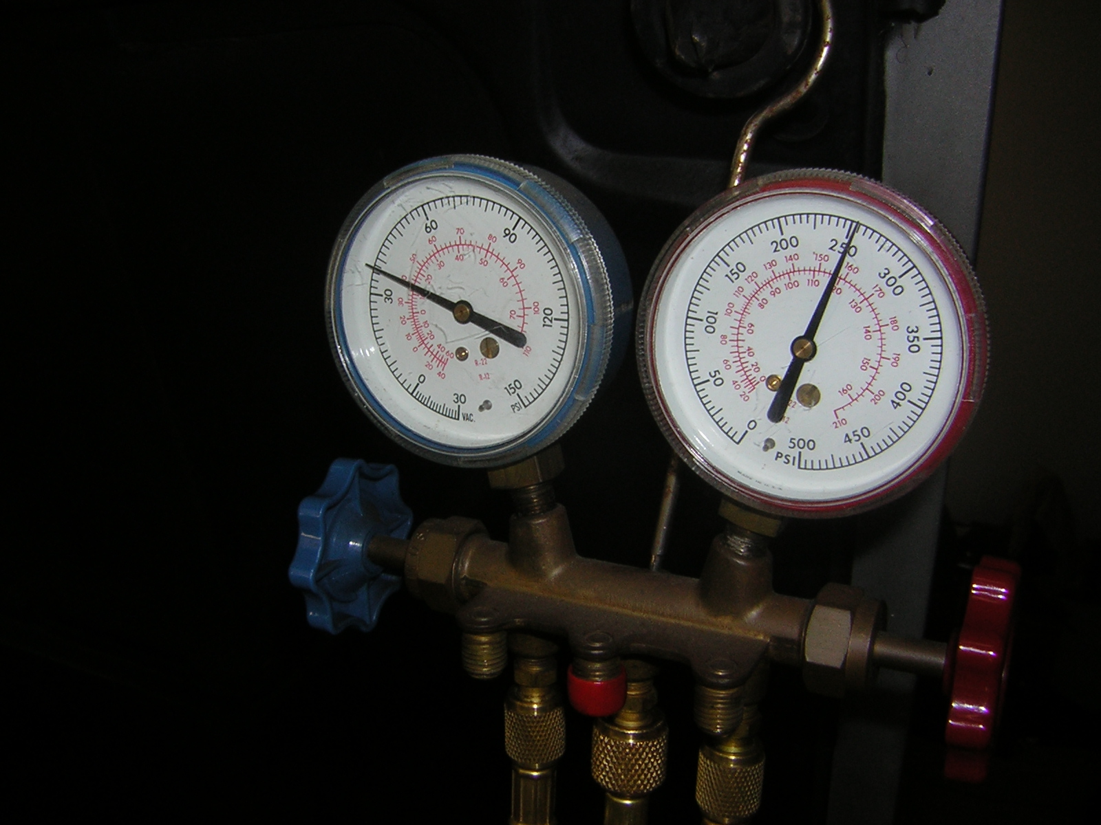
- Low pressure gauge target is in the 30-32 psi range (20-40 is acceptable) with gauge valves closed.
- High pressure gauge target is in the 175-275 range with gauge valves closed.
- Target temperatures at the A/C vent is in the 38-45 degree F range.
- Once system is charged:
- Close low pressure valve on gauge set
- Close valve on R-12 can
- Turn off car
- Disconnect hoses from car, but watch for high pressure spray from the red hose
- Done
Jeff
Last edited by 62Jeff; 07-10-2011 at 02:27 PM. Reason: Added detail on vacuum target. Moved "turn off car" to after closing the low press. valve.
06-26-2011, 02:33 PM
#4
Melting Slicks

There really should be an A/C section in the FAQs. This belongs in there, joining Mechron's A/C 101.
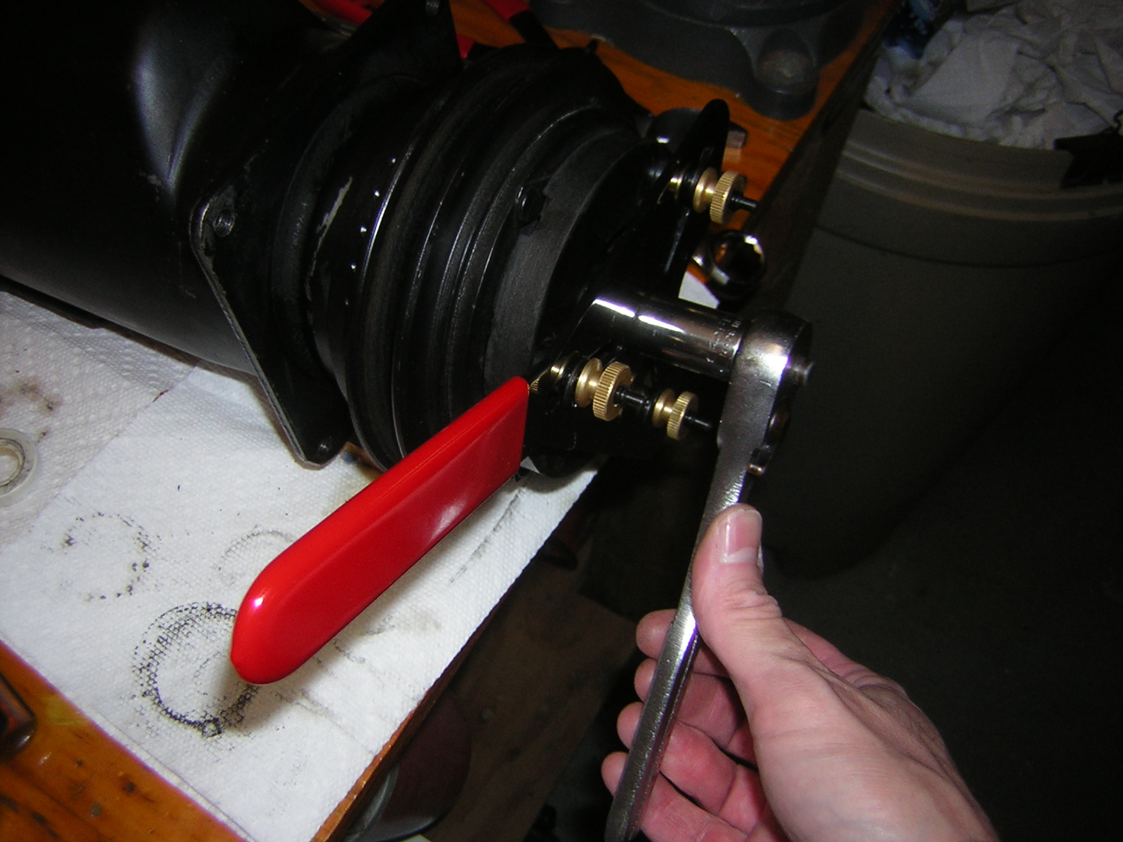
FWIW, here are the 2 types of snap-ring pliers that will make easy work of the seal seat retaining ring. The red-handled ones are current production. The KD2020A's are vintage.
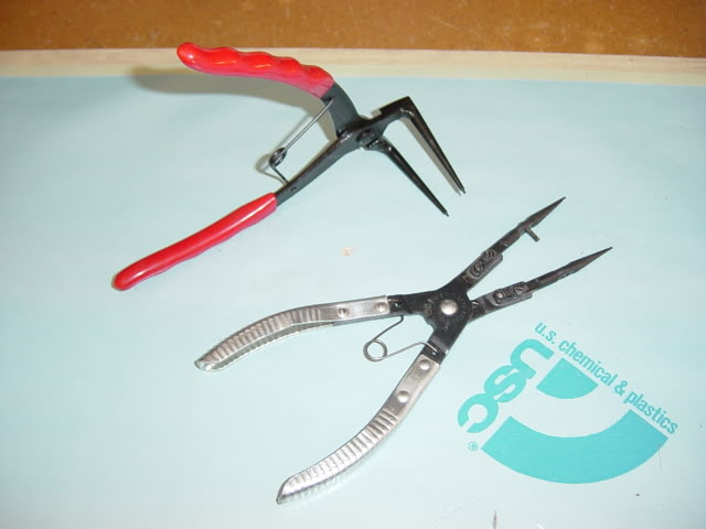
FWIW, here are the 2 types of snap-ring pliers that will make easy work of the seal seat retaining ring. The red-handled ones are current production. The KD2020A's are vintage.
06-26-2011, 02:52 PM
#5
Tech Contributor
Thread Starter
Based on your recommendation of last week, this morning I went ahead and grabbed KD2020A and KD2020B so that I may have them in my collection for the next time I do this to one of my cars.
06-26-2011, 03:26 PM
#6
Melting Slicks
Jeff:
those KD's really make the job "almost" a pleasure. The fat-tipped pair are for the big-*ss ring that secures the clutch coil. It's another bugger without the right pliers.
Mike
those KD's really make the job "almost" a pleasure. The fat-tipped pair are for the big-*ss ring that secures the clutch coil. It's another bugger without the right pliers.
Mike
06-26-2011, 03:38 PM
#7
Team Owner


Member Since: Oct 2000
Location: Washington Michigan
Posts: 38,899
Received 1,856 Likes
on
1,099 Posts

Jeff, I know just enough about A/C to be dangerous, but that's a great DIY post; now I understand about that seal. 
06-26-2011, 05:40 PM
#8
Race Director


Jeff:
EXCELLENT tutorial and write-up! The photos and explanations are first rate. Glad you got this job done.....hopefully the seal will last awhile without giving problems. What didn't go right with the second lip seal??
I would recommend that with all the other gear you have acquired for your AC system work, you add a refrigerant leak detector. The one I have that works very well is the Inficon TEK-MATE. That way you can ensure that you don't have any significant refrigerant leaks in the system. With the price and availability of R12, having and using this detector just makes sense. It identifies both small and large leaks, although with a large leak you really don't need the detector...you can just follow the oil trail.
Thanks again for the time and effort to put this post together.
Larry
06-26-2011, 05:47 PM
#9
Tech Contributor
Thread Starter
Thank you Larry.
The second double-lip seal, the one with the smaller hole, didn't seal any better than the wrong seal with the big hole. I KNOW the seal material was very stiff on the small seal, I THINK installing it over the seal protector, permanently disfigured it.
The second double-lip seal, the one with the smaller hole, didn't seal any better than the wrong seal with the big hole. I KNOW the seal material was very stiff on the small seal, I THINK installing it over the seal protector, permanently disfigured it.
06-26-2011, 05:49 PM
#10


I use to have an air LT-1. It blew up the compressor a couple of times so I learned to rebuild it. After much looking around back in the 70's I accumulated what I needed. The kit you showed is a life saver. This is one of the best posts I've ever seen on AC in a mid year.
Well done!
Well done!


 06-26-2011, 10:41 PM
#16
Drifting

Great job, Jeff. I've never seen a detailed write up on this subject. I can't wait to get at mine. I'm going to follow your lead and go with the original seal system. Well done!! Jim
06-27-2011, 06:40 PM
#17
Tech Contributor
Thread Starter
Thank you all for the kind words guys.
I hope this seal replacement will last, but if nothing else I've collected the tools and the confidence to dig in further the next time if needed on this car, and go full steam ahead on the A/C of my other older cars.
Jeff
I hope this seal replacement will last, but if nothing else I've collected the tools and the confidence to dig in further the next time if needed on this car, and go full steam ahead on the A/C of my other older cars.
Jeff
07-09-2011, 08:13 PM
#18
Tech Contributor
Thread Starter
So far so good.
Fingers crossed this luck keeps up.
Jeff
- Two weeks
- 120 miles of A/C driving
- 3 hours of time with the A/C on
- No bubbles in the sight glass yet
- A/C vent temps still just above 40 degrees even idling in 93 degree temps while sitting in the fast food drive-through line this evening.
Fingers crossed this luck keeps up.
Jeff
08-28-2011, 03:24 PM
#20
Tech Contributor
Thread Starter
I edited the opening post to include more detailed instructions on using the Robinair machine to recover the R-12 from my system.
This entire thread exists in part because I don't want to have to remember all these datails the next time I have to do this for one of my cars
This entire thread exists in part because I don't want to have to remember all these datails the next time I have to do this for one of my cars