Trailing arm shim that hold in place and keeps the shims from falling off the car
 09-14-2011, 02:35 PM
#1
Le Mans Master


Thread Starter

Who sells the shim that have one hole on each end that holds all of the shims in place. This is used on 1963 to 1969 Corvettes
It have a hole in each end so it keeps the shims in place after you have used the cotter pin
Each end is like the the one on this picture

You can see it here on this film about installing trailing arms
http://www.vtechcorvette.com/Video-s-.html
It have a hole in each end so it keeps the shims in place after you have used the cotter pin
Each end is like the the one on this picture
You can see it here on this film about installing trailing arms
http://www.vtechcorvette.com/Video-s-.html
Last edited by TheSaint; 09-14-2011 at 02:45 PM.
 09-14-2011, 03:00 PM
#3
Melting Slicks


The cotter pin is retained by a hole in the frame, not by the no-slot shim. You don't need the shim in your picture. Just get a 3/16 12" extension drill and drill the hole in the frame for the cotter pin. It will then work just like a late C3.
Check archives for some good info on where to drill.
Harry
Check archives for some good info on where to drill.
Harry
09-14-2011, 04:15 PM
#5
Race Director


They have the early type with a hole on each end, or the later type with a hole on one end and a slot on the other end. Take your pick.

Larry
09-14-2011, 06:23 PM
#6
Le Mans Master
Thread Starter
Thanks Powershift
I searched all of the big vendors but could not find the shims.
I just thought it was used one of those shims on each side to hold the shims to the trailing arm bolt?
I searched all of the big vendors but could not find the shims.
I just thought it was used one of those shims on each side to hold the shims to the trailing arm bolt?
09-15-2011, 07:05 PM
#7
Team Owner


Member Since: Oct 2000
Location: Washington Michigan
Posts: 38,899
Received 1,857 Likes
on
1,100 Posts

Photo below shows the location of the cotter pin - it's at about 4 o'clock relative to the pivot bolt.
09-21-2011, 11:37 AM
#8
Le Mans Master
Thread Starter
Paragon has both types of shim - the one with the hole in one end and a slot in the other end is their #3618K; the slotted end goes over the pivot bolt, and the long cotter pin (#7216) through the frame goes through the end with the hole to retain the shims.
Photo below shows the location of the cotter pin - it's at about 4 o'clock relative to the pivot bolt.
Photo below shows the location of the cotter pin - it's at about 4 o'clock relative to the pivot bolt.
I will do it like you say JohnZ
The picture is saved and stored on my computer
12-08-2012, 09:49 AM
#9
Hi
I'm installing trailing arms to my 68 after rebuild.
I have the slotted shims from Paragon as seen on the other post.
I'm about to drill the hole in 4 O'clock position, but?
However, the ones that I have are too long to fit in the frame pocket as they do in post #7.
Do I have the wrong shims, or can someone chime in on whats wrong here?
http://i1177.photobucket.com/albums/...E338A3E530.jpg
http://i1177.photobucket.com/albums/...E3433D9CEA.jpg
No way that these shimns can be tugged into the frame.
Thoughts are well appreciated.
Lars
 12-08-2012, 10:16 AM
#11
Race Director
That's okay......maybe we can still help.
The 1963 cars had long shims with a hole on one end and a slot on the other. They stuck out like the ones shown in your photos. Perhaps you have them.
For 1964 to about 1968 shims with the two holes were used.
Then Corvette again went to a shorter slotted shim with one hole and used the long cotter pin.
You need for someone to provide dimensions on the shorter slotted shims that use the cotter pin: overall length and depth of slot. Then you can compare to what you have.
Or order the ones from Paragon that JohnZ referenced above. You know they will work. (I realize that this is more difficult living outside the USA).
Larry
12-08-2012, 12:02 PM
#12
Melting Slicks
An old school alignment shop used the slotted shims on mine. He then ground down the end edge so they would tuck into the pocket. The mechanic said he's never had any fall out.
Brian
Brian
12-08-2012, 01:45 PM
#13
Hi
I got the same as JohnZ.
They are 4.5" long with 1.5" slot.
Will see if I can find the dimension on the shorter shims.
Otherwise I can do as Brian is suggesting. Cutting exsisting shims to correct length.
Just wonder of the hole in my frame is not shallow enough?
I got the same as JohnZ.
They are 4.5" long with 1.5" slot.
Will see if I can find the dimension on the shorter shims.
Otherwise I can do as Brian is suggesting. Cutting exsisting shims to correct length.
Just wonder of the hole in my frame is not shallow enough?
Last edited by naasaa; 12-09-2012 at 03:09 PM. Reason: Misspell
05-01-2018, 10:34 PM
#14
Advanced

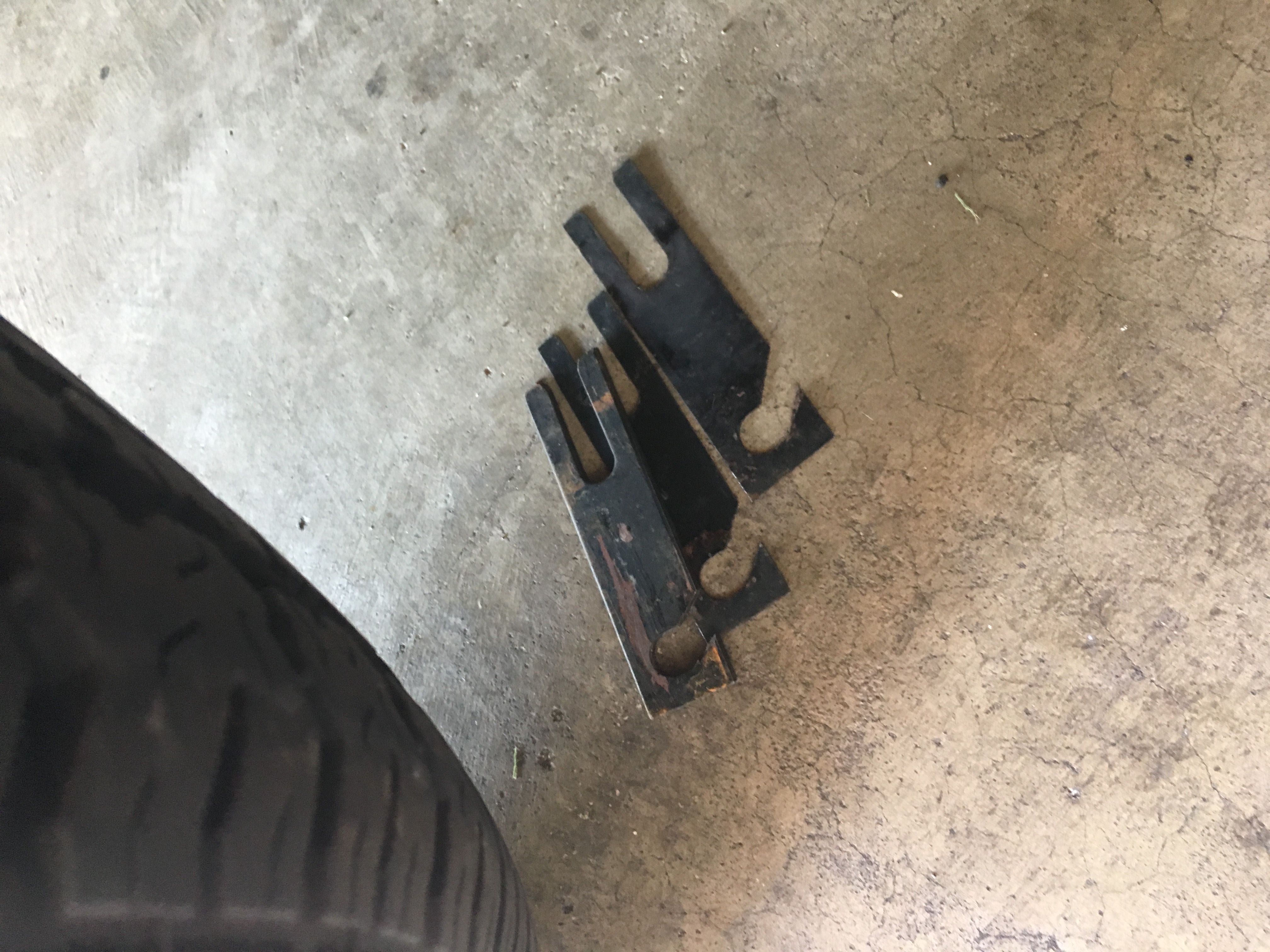
I just had my shims drop out from one side of my �63 (VIN 8555). Car is a previous Top Flight and I want to retain originality. Can someone tell me the correct shim geometry and is a pin used?
05-01-2018, 10:35 PM
#15
Advanced
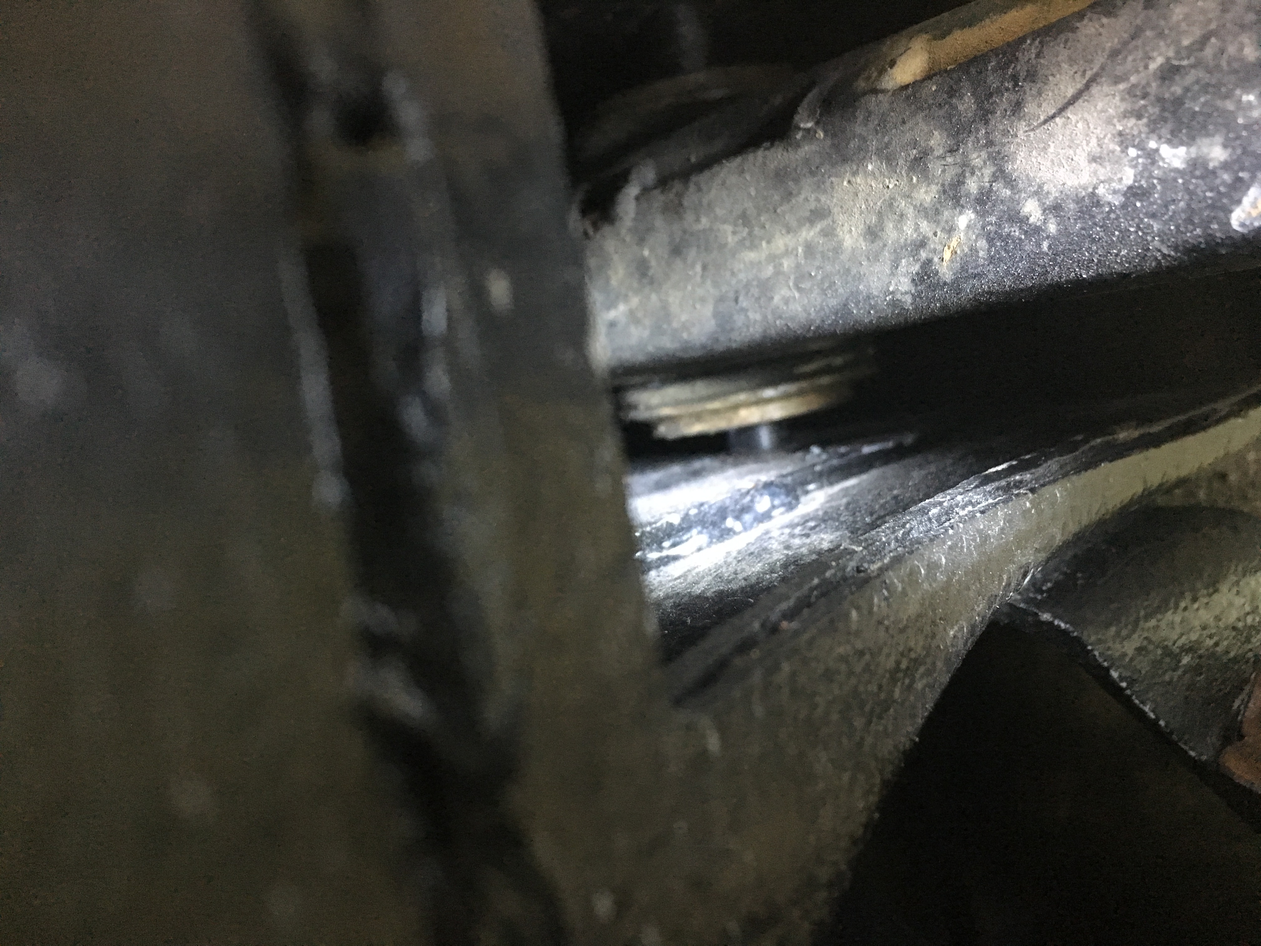
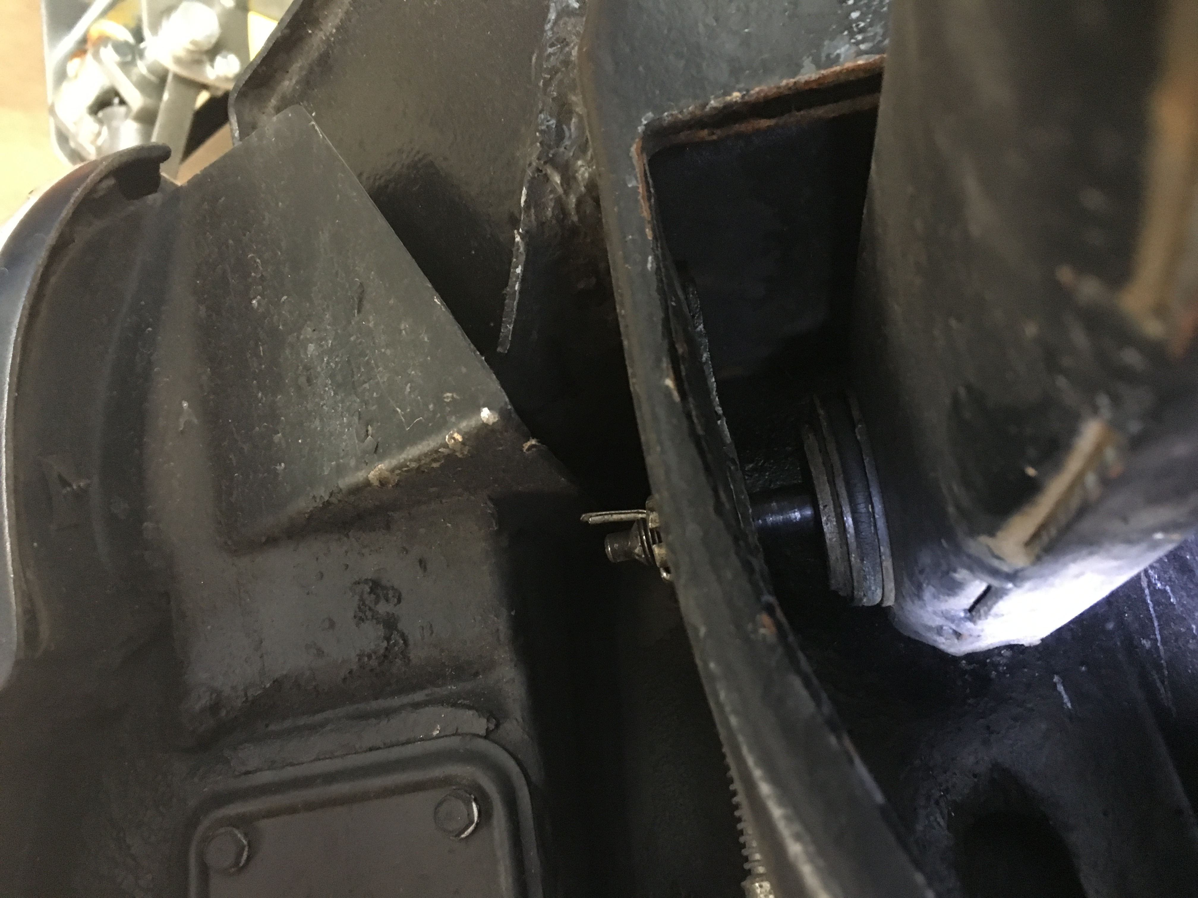
First pic is of shims that came out (not all, some lost on the road). Other pics show both sides of the bolted assembly, gap totally open now. What is the proper way to return this to the correct installation for an early '63?
Last edited by Rattenni; 05-01-2018 at 10:50 PM. Reason: Proper pic attachment
05-01-2018, 10:55 PM
#16
Melting Slicks
Member Since: Feb 2007
Location: OP Kansas
Posts: 2,923
Received 134 Likes
on
95 Posts
C2 of Year Finalist (appearance mods) 2019

I had the same thing happen shortly after I bought my car. I bought new shims on-line and brought the car in for an alignment. I'm pretty sure most people can't do it correctly by themselves, you need special equipment.
05-01-2018, 11:00 PM
#17
Melting Slicks
The only way to correct this properly is to remove the control arms and reinstall the bushings with new sleeves. Not an easy operation but it's the ONLY way to make sure the two bushings are installed and compressed completely before the center tube is flared.
05-01-2018, 11:03 PM
#18
Advanced
I have a hard time believing that there is an underlying bushing issue given that the car has only 500 miles since a complete nut & bolt restoration?
Last edited by Rattenni; 05-01-2018 at 11:04 PM. Reason: typo
05-01-2018, 11:20 PM
#19
Melting Slicks
There are numerous threads on this subject (on a few different boards) and all boil down to improper bushing installation.
If the inner sleeves are not making actual contact with each other, the pivot bolt is tightening on rubber bushings instead of an actual metal outer sleeves. If that's the case, you will never be able to secure that stack. When that's the case, the entire bushing with sleeves rotates as the suspension goes through jounce/rebound. That rotates the shims along with the outer shell and they can't possibly stay in place that way.
Search threads here (and over at the NCRS site) for a better description of this problem. I posted great info here and over there on this.
I have a great image that I made that should explain why this has to be done this way. If I can dig it out, I'll post it.
05-01-2018, 11:26 PM
#20
Melting Slicks
Here's the link to a previous discussion that explains the issue and I even posted a hand modified drawing that should explain it.
https://www.corvetteforum.com/forums...trol-arms.html
https://www.corvetteforum.com/forums...trol-arms.html