C1 Steering shaft split retainer
 07-27-2012, 07:30 PM
#1
Drifting


Thread Starter

I'm trying to chase down one of these split retainers for my now rebuilt 1960 steering box BUT though I've placed a thread in the C1 parts for WTB I've had no replies SO I need to ask the question! Was this fitted to all C1's particularly the 1960 C1? I've not seen this in any parts catalogue or any assembly manuals only reference is in the 'sticky' for the steering box rebuild. The purpose of this split ring is to put preload on the top steering shaft bearing.
Oh, and if you have one you can also let me know.
Thanks in advance
Oh, and if you have one you can also let me know.
Thanks in advance
 07-27-2012, 09:35 PM
#2
Pro

I think what I see there is part of the upper column bearing. The old one may have been defective and was replaced at one time. I have taken many of these apart and don't remember this spacer. I would just ignore it.
Pierre
Pierre
07-28-2012, 03:19 AM
#3

I think you are seeing remnants of the upper bearing.
Last edited by stratplus; 07-28-2012 at 03:28 AM.
07-28-2012, 04:44 AM
#4
Drifting
Thread Starter
This is the text that goes with the photo: "At the upper end of the steering shaft is a bearing and horn contact unit, along with a split retainer which puts preload pressure on the upper bearing when the spring and steering wheel are installed. DON’T LET THE SPLIT RETAINER FALL TO THE FLOOR AND GET LOST!"
And this is the information posted by DZAUTO: http://api.viglink.com/api/click?for...13434648547773
I'm still not convinced that it is part of the bearing
And this is the information posted by DZAUTO: http://api.viglink.com/api/click?for...13434648547773
I'm still not convinced that it is part of the bearing
07-28-2012, 07:38 AM
#5
Burning Brakes

[QUOTE=mickatbp;1581424815]This is the text that goes with the photo: "At the upper end of the steering shaft is a bearing and horn contact unit, along with a split retainer which puts preload pressure on the upper bearing when the spring and steering wheel are installed. DON�T LET THE SPLIT RETAINER FALL TO THE FLOOR AND GET LOST!"
that split retainer goes between teh top bearing and spring,,, i used a split ring from a 1/2" conduit coupling....
that split retainer goes between teh top bearing and spring,,, i used a split ring from a 1/2" conduit coupling....
07-28-2012, 07:58 AM
#6
Race Director


Member Since: Mar 2001
Location: Mustang OK
Posts: 13,845
Received 3,766 Likes
on
1,669 Posts
2023 C1 of the Year Finalist - Modified
2015 C1 of the Year Finalist

[QUOTE=knockbill;1581425057]
Yep, I can not add any more.
Although, It might be easier to find one off of a 49-54 passenger car.
Tom Parsons
This is the text that goes with the photo: "At the upper end of the steering shaft is a bearing and horn contact unit, along with a split retainer which puts preload pressure on the upper bearing when the spring and steering wheel are installed. DON�T LET THE SPLIT RETAINER FALL TO THE FLOOR AND GET LOST!"
that split retainer goes between teh top bearing and spring,,, i used a split ring from a 1/2" conduit coupling....
that split retainer goes between teh top bearing and spring,,, i used a split ring from a 1/2" conduit coupling....
Although, It might be easier to find one off of a 49-54 passenger car.
Tom Parsons
07-28-2012, 08:11 AM
#7
Drifting
Thread Starter
Tom, how important is the fitment of this split ring? Any leads on where I can get one?
KBill, Can you show me a photo of this conduit coupling split ring ............. or/and tell me where to get one from.
Thanks guys
KBill, Can you show me a photo of this conduit coupling split ring ............. or/and tell me where to get one from.
Thanks guys
Last edited by mickatbp; 07-28-2012 at 08:17 AM. Reason: more info added
07-28-2012, 09:11 AM
#8
Burning Brakes
send me your email, and i'll attach pics....
07-28-2012, 11:10 AM
#9
Drifting
Thread Starter
k'bill, can you send to both michael.stumpf@se1.bp.com and michael.stumpf@bigpond.com I'm on night shift at the moment (1800 to 0600hrs) but just incase I don't get them until tomorrow morning when I'm at home
07-28-2012, 08:32 PM
#10
Drifting
Thread Starter
Here is a response from Plasticman:
It does exist (as DZAUTO stated). Here it is lying in all it's glory (on wood flooring):
Here it is on the 62 Vette column, from whence it came. Note that it has been slid back on the shaft (not down in the col. bearing) for photo purposes only:
Skids,
Don't know if this is what you are looking for........but it does take up the side to side slop in a C1 column.
Plasticman
--------------------------------------------------------------------------------
Seems we have two parallel threads running at the same time ..... so not a broken bearing race or remnant but a ring that does serve a specific purpose ............. does any one have a spare? I guess everyone will be looking for one now!!!
Last edited by mickatbp; 07-28-2012 at 08:41 PM.
07-29-2012, 04:39 AM
#12
Drifting
Thread Starter
Okay,
The split ring retainer dimensions that I need to have a go at copying the original are:
1. Length of chamfer.
2. Full length from top of ring to base of chamfer
3. Ring diameter when ring is fitted to steering shaft
4. Radius under ring (use the blunt end of a drill bit until the drill diameter fits the radius - then give me the drill size)
5. Wall thickness (of ring)
Thanks in advance
Last edited by mickatbp; 07-29-2012 at 04:42 AM.
07-29-2012, 08:38 AM
#13
Drifting
Thread Starter
While I wait for some measurements, I came across a couple of 3/4" swageloks and I'm going to have a go at modifying the front ferrule to see if I can get it to look like the split ring retainer.
Last edited by mickatbp; 07-29-2012 at 08:48 AM.
07-29-2012, 11:24 AM
#16
Race Director

Member Since: Nov 2000
Location: Beverly Hills (Pine Ridge) Florida
Posts: 10,152
Received 525 Likes
on
374 Posts
Mick,
Here is a first go. I can add dimensions as needed, but think that measuring in it's relaxed state is best (for duplicating purposes). Material thickness is .030", but it is worn at the minor diameter end (forming that chamfer), and the material thickness varies from .011" to .020". If I was you, I would not be concerned initially about duplicating that wear / chamfer, and just leave it .030" thick (material thickness) on both ends.
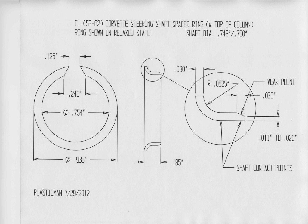
Plasticman
Here is a first go. I can add dimensions as needed, but think that measuring in it's relaxed state is best (for duplicating purposes). Material thickness is .030", but it is worn at the minor diameter end (forming that chamfer), and the material thickness varies from .011" to .020". If I was you, I would not be concerned initially about duplicating that wear / chamfer, and just leave it .030" thick (material thickness) on both ends.
Plasticman
Last edited by Plasticman; 07-29-2012 at 11:31 AM.
07-29-2012, 12:04 PM
#18
Drifting
Thread Starter
Plasticman, can you email me split ring spec sheet so I can print it with good detail. to michael.stumpf@se1.bp.com and also to michael.stumpf@bigpond.com . Last night shift tonight so if I miss it at work can print at home ......... I'd like to change the dimensions to metric ............ sorry that's the way we role in Aus.
Thanks for going to so much trouble
Thanks for going to so much trouble
07-29-2012, 12:43 PM
#19
Race Director
Member Since: Nov 2000
Location: Beverly Hills (Pine Ridge) Florida
Posts: 10,152
Received 525 Likes
on
374 Posts
Plasticman, can you email me split ring spec sheet so I can print it with good detail. to michael.stumpf@se1.bp.com and also to michael.stumpf@bigpond.com . Last night shift tonight so if I miss it at work can print at home ......... I'd like to change the dimensions to metric ............ sorry that's the way we role in Aus.
Thanks for going to so much trouble
Thanks for going to so much trouble
It has been sent in jpg format (now get back to work)...........
Steve59,
Thanks!
Plasticman
Last edited by Plasticman; 07-29-2012 at 12:45 PM.
07-29-2012, 07:48 PM
#20
Drifting
Thread Starter
Plasticman, at home now .......... bugger the sleep ........... had to try the idea I came up with for the split retainer ........... HOWEVER ........... now I have more questions...........?
Two pictures, one showing the split retainer options and one showing the gap between the steering wheel and the top bearing (upper face of the inner race) which must be close to an inch when the steering wheel is fitted (and the indicator mechanism is removed as this plays no part in the tighteness of the shaft in the column).
All of the 'split rings' are 3/4" same diameter as the steering shaft. the swagelok split ring(s) are a press fit as is the brass ring while the nylon and copper are a tight slip fit. My question is what keeps the split ring against the inner race of the top bearing .......... is it the press fit? And what stops it from working lose, initially I thought the back of the steering wheel centre pushed up against the split ring and that is why the 0.185" length was critical but this seems not to be the case.
What holds the split ring against the inner race of the top bearing to ensure any slop between the steering shaft and bearing is cancelled and remains so until the column is disassembled again? I am almost tempted to put a piece of rubber hose (or some other spacer) over the steering shaft between the split retainer and the (seated) steering wheel to ensure a constant pressure is applied to the split ring. I assume the ring is split as a solid press fit ring would be impossible to remove once installed.
If the press fit is the important factor in the success of the split ring in removing the slack then the 0.185" is irrelevant and the shaft and race contact points are crutial in removing the slop. And this means the exact design of the split ring is not inportant either as long as it provided these contact points.
Your thoughts and insight would be much appreciated.
Last edited by mickatbp; 07-29-2012 at 07:51 PM. Reason: spelling