When you click on links to various merchants on this site and make a purchase, this can result in this site earning a commission. Affiliate programs and affiliations include, but are not limited to, the eBay Partner Network.
Well, this is as good of time as any to talk about my rear suspension issues/concerns. Then later I can go right to explaining how I fixed them.
First both spindle supports are worn out where the strut rods connect to them. Both holes, the round one and the "D" shaped one. One support is a lot worse than the other but both are bad. And to make it worse, the knurls on the lower shock mounts are worn away. There is not even enough material on one spindle support for the lower shock mount to grab. It just spins. I do not like the way this assembles even if the parts were good. I can get new parts but would rather see an assembly that is easier to assemble and disassemble than this design is.
Next, I bought an after market offset trailing arm. Having it set in place it looks like it will interfere with the shock. The clearance is very little if any. I moved the shock to the outside of the upper mount and like the way it looks mounted there a lot better. If I go this route I would have to beef up the upper mount to support the shock load on the outside. I just have a long bolt through there now. I would also have to notch the fiberglass in the rear inside of the cockpit for clearance. In the pictures below I have the shock moved out at the top.
And of course there is the rear sway bar. The original mounting holes are too far out board on the frame for the beefier bar. Using them causes the bushings to deform just like the front did. I can move them in easy enough but I also do not like how wide the bar is. It hangs out past the outside edges of the frame and I am afraid that it or the linkage will interfere with the wheels and tires.
Wide rear sway bar clamped in place.
So there you have it. All the things with the rear suspension design that I am concerned about and looking at alternatives for.
Wow - yours is an outstanding project. I would love to possess the skills and tools to be able to replicate what you're doing. Thanks for taking time to document what you're doing!!!
Wow - yours is an outstanding project. I would love to possess the skills and tools to be able to replicate what you're doing. Thanks for taking time to document what you're doing!!!
Thanks everyone. I really like doing this stuff. The car project and the blog. And to tell the truth, I feel pretty lucky to be able to do everything that I am doing. I got real lucky when we moved back to our home town and I gained access to a full machine shop. Without it I wouldn't be doing a lot of what I am doing.
I have been really busy in the machine shop working on my stuff. It seems like I have a little of everything going. I have managed to finish a few small items that I can talk about and show you.
A few weeks back I showed you the new lever that I made for the parking brake mechanism under the car. Well here it has been powder coated and I have the bearings pressed in. I made a spacer to go between the frame bracket and the lever. It fits in the larger hole on the frame bracket and then has a raised portion at the top for the lower bearing to ride on. I bought a 3/8" shoulder bolt to secure it all. I will install the cable and make a new rod later when the rear suspension is complete.
Parts for the new lever and the drawing for the bottom spacer. Up above is the shoulder bolt, the spacer, washer, and lock nut.
Here is a good example of something that you think would be simple and turned out not to be.
My old differential fill plug was pretty corroded. The threads were kind of messed up and it would not thread all the way into the housing. I could buy a new one for $15.00 but thought hey, why not make one out of stainless steel. It actually would have been a lot easier if it wasn't for that 3/8" hex socket I wanted to add. That one feature took two hours on a CNC mill with all the little drilling and machining steps it took to make it.
A long while back I bought a stainless steel replacement fuel line for a 1965 big block. It turned out to be a 3/8" line which is a good thing (the size I needed). I also plan on running an after market EFI system that claims it will work with a returnless fuel system which I also thought I was going to run. I have since changed my mind. I recently found a C2 direct replacement fuel tank set up for an in tank fuel pump. The fuel pump flange mounts on the top of the tank and has fittings for a supply line, a return line, and a vent. It then has a separate flange for a sending unit. I now plan on using this tank. When I get the tank I will route a second fuel line for the EFI system.
The real story here in the fuel line that I already have (Replacement big block line). It is really designed to be a suction line and has barbed fittings for hoses and clamps. I found new fittings to make the line better for running pressurized fuel. I simply cut off the barbs and cleaned up the ends. These fittings then slid right on and are secured with a nut and ferrule type joint. The connection end is threaded and I can get lots of different fittings that it will work with.
I have completed some machining to the rear spindle supports. There may be more, there may not. I figured I might as well try something and maybe make it better before I spend several hundred dollars to buy new ones and go back to the OE design.
If you remember my problem was with the holes at the bottom of the supports that are used for attaching the strut rod. They were enlarged. One was so bad that the knurls on the lower shock bolt would not even come close to engaging because the hole was so worn out.
The first step was to clean up the sides of the ears the holes go through. I had two reasons for doing this. First I was hoping to make both ears the same thickness. Second, it would give me a clean flat surface to align to when aligning the holes for boring to a larger size. I ended up taking between .020 and .030" off each side. This actually worked out quite well. On both parts I was able to make each ear .330" thick and have a measurement of 1.75" between the inside of each ear. It was almost as if they were meant to be that way. These dimensions all being the same will make designing the actual lower strut rod mounting hardware easier. I will show you this later.
Next step, bore the holes to a new larger size. I did the really bad one first. I wanted to bore the worst hole just big enough to clean it up and then all the others to match. The final size ended up being .750". I bored both ears with the same set up at the same time. Straight down through one ear and then the other. I used a .6875 end mill to remove most of the material and then a boring bar to get to the final size. Boring bars can flex some so I was only removing .010" at a time.
Cleaning up the sides of the ears. Here the spindle support is bolted to a plate using the surface that bolts to the trailing arm. I made a custom rod to fit through the holes to indicate the part to. I had already made the plate and planned on using it to check bearing end play later.
Boring the holes. Here I am cleaning the bores up to the final size using a boring bar. The spindle support is mounted to an angle plate using the bearing race bores in the support. The newly cleaned ear surfaces were then leveled.
O.K., I bored out the lower holes in the rear spindle supports. These were used for mounting the strut rod. Now the holes are too large, so how to fix that. My strut rods are now going to use large heim joints. The joints have a .625" hole and the swivel ball is 1.375" wide. My spindle supports have .750" holes and are 1.75" wide. I need to make a shoulder bolt that will go all the way through both holes, will be .75" in diameter at one end, and .626" diameter at the other end for the heim joint. The .75" section can also serve as a spacer to compensate for the 1.375" wide heim joint in the 1.75" space. Then make a nut that does the same thing at the other end. Hard to explain, but maybe the picture will help.
I used 303 stainless steel to make these which is soft. I wish we would have had a piece of 400 series stainless steel which I could have had hardened. I am pretty sure it will be alright It will no longer require a high torque. I can use thread locker. I can also drill and pin the nut end. Also none of the center of the bolt is exposed. The chances of it shearing are pretty low. The ears on the spindle support would probably break first.
The first spindle support has the heim joint assembled. The second is laid out so that you can see the machine features and how it assembles.
The bracket that bolts to the bottom of differential remains the same. But again ,my heim joints are smaller than the large rubber bushing rod end that came with the suspension kit. So I needed to make some more spacers to make up that difference in space. The kit also came with square washers to use on the outside of the bracket and a .500" bolt which even fit the rubber bushing rod end loose. The bracket still has the slots that were used for the OE solid strut rods and were adjusted with the round cam like washer. That is what the square washer was for. To keep the bolt from sliding up and down. I replaced the square washer with nicer looking round ones and the .500" bolt with a .625" shoulder bolt.
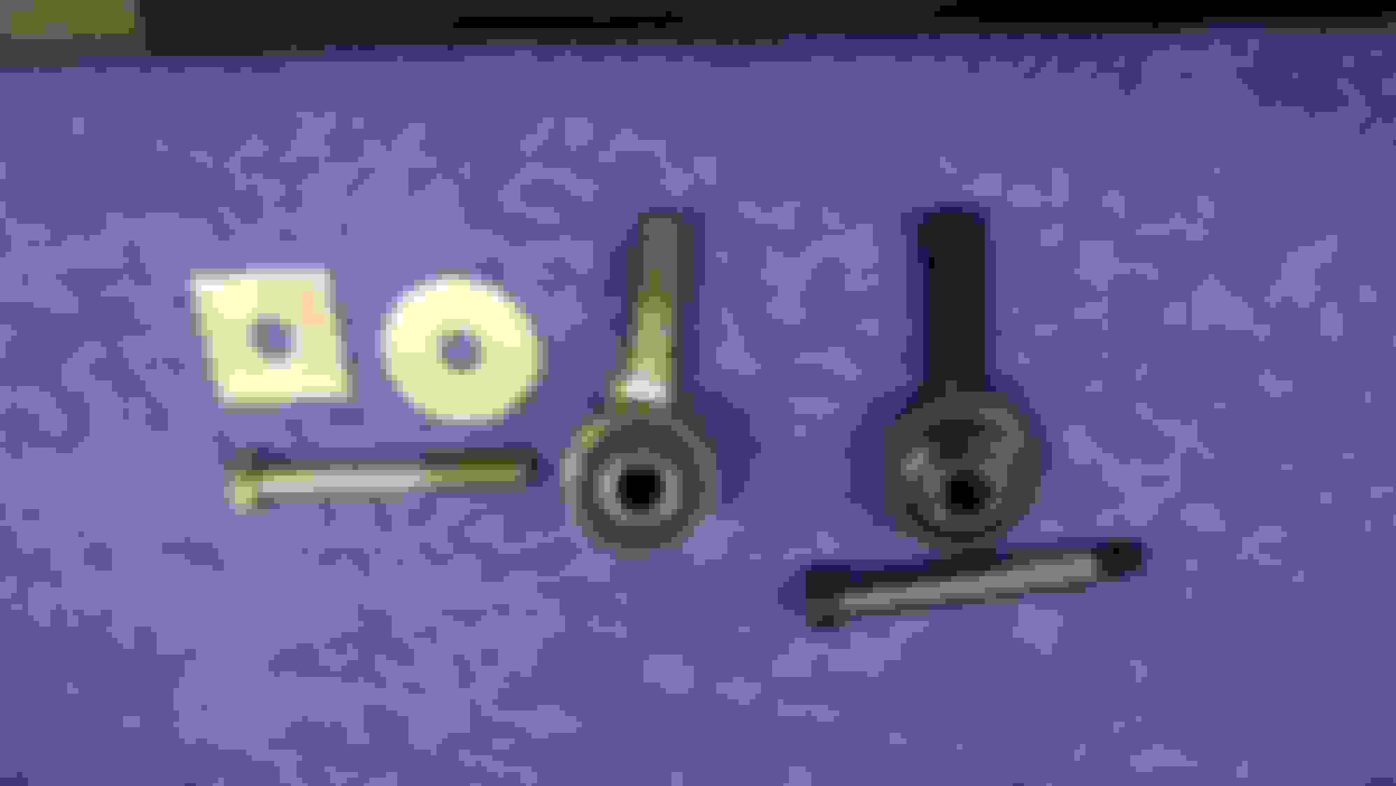
On the left are the rubber bushing rod end, washers and bolt that came with the kit. On the right are my new heim joint and should bolt.
Above the hein loint , spacers. and shoulder bolt are installed in the strut rod bracket. Below the parts are laid out in order of assembly. I will use a lock nut on the shoulder bolt during final assembly.
Just came from the garage working on a winter project - waiting for spring - when I just read your last few posts.
I appreciate your insights in how you tackle these perils you've come across on your build.
Previous owners have obviously not been good to her - neglectful I'd say.
I like what your doing with the spindles especially the heim joints you've created. .
Also nice job on the fuel line. . What kind of EFI are you going to run? I'm installing a TBI FiTech and their sump kit right now. No mods for my gas tank.
Keep the updates coming.
65-StingRay
Wayne
Thank you, I have gone back and forth a couple of times on the EFI but I am leaning toward a FAST system. They recently came out with a multi port EFI for big block Chevys and I am really considering that.
If your not in a rush FiTech just came out with an 800HP version and a 400HP one as well. Go to there website and check it out. Their pricing is unbeatable right now. Other companies are scrambling - Holley now has $1000.00 version. I was always a believer that they were all over priced.
FAST 2.0 is popular.
Here's a pic of what I.m putting in. wiring spread out all over
Annular discharge and the ecu is part of the throttle body.
Shot of the sump w/efi 340 pump inside.
Good Luck with whatever EFI you choose.
Like sonksen_design said - love seeing the machine work.
A couple of weeks ago I had started assembling the front brake rotors and calipers. I made a change to the front hubs that I have not shown you yet but hopefully will soon. Anyway I had gotten the rotors on and decided to check their run out. The passenger side came in at about .0025" out. I thought that was pretty good. Not sure I could ask for better. The drivers side If you remember had a bent spindle that I replaced. When I measured the run out it, it came in at .008" out. A little disappointing. The rotors checked out almost perfect so there may be an issue with the hub on that side. I have not done anything with the front since. But it did get me thinking about the rear spindles and this section is about them.
I pulled the trailing arms apart a long while back and did not find anything out of the ordinary when doing so. I have already done some work to the rear spindle supports as you have seen and for the most part I figured I have two good rear spindles. I have seen ads for precision machined rear spindles that cost about $300 each. All specs are within .001" or less. I wanted to see how close my spindles were to this and/or how close to that spec I could get them.
The modification that I was making to the front hubs I also wanted to make to the rear spindles. This was to thread the old rivet holes. I threaded the front to 3/8-24. I have some pan head screws and it worked out real nice. The screws are just meant to hold the rotors on. They make it easier to install or service the calipers. With out the old rivets or screws the rotors would just flop around. The problem with making this modification to the rear when I got there was that the existing holes were too big for that thread size. I couldn't go with a bigger thread size because the heads on the screws would be too big for the counter sinks in the rotors and I did not want to go any deeper with those. O.K., I will drill them out and bush them. That went well for one but the other seemed to be hardened on the back side and I had to bore the holes on the mill. I got them done though.
Now for the nightmare. Each spindle has a center hole formed or drilled at each end. If you put the spindle in a lathe and spin it between those centers the bearing surfaces should spin true with .001" or less of run out. Not the case here. I figured that the centers were not in alignment with the bearing surfaces. I put each spindle in the lathe one at a time with the flange in the jaws and then bumped it around until both bearing surfaces were spinning true and re cut the center on the threaded end of the spindle. After this step I needed help from one of the guys. It was getting pretty complicated for me.
At this point we were working with just one of the spindles. We basically did the same thing to the flange end. We put the spline end in the lathe and bumped it around until the two bearing surfaces spun true again. Then used a boring bar to re-cut the center in the end of the flange. We took the part out and spun it between the two new center holes and this time it was a lot better. The spline end bearing surface was near perfect but the flange end bearing was better but still had .003" run out. My buddy still thought we could get better and after about 5 more tries at re cutting the center hole and a couple of backwards steps we finally got it. The spindle would spin between centers with less than .0005" run out at each bearing surface.
Next with it still between centers we looked at the run out on the face of the flange. Yep, almost .007". That would translate right to the rotors when bolted on. But an easy fix at this point. A couple of lite cuts on the face in the lathe and it was down to .0005" run out also.
So, I now have one rear spindle that when spinning on the bearings should have .001" run out or less on the flange.
Boring out the rivet holes for the threaded inserts.
Indicating the bearing surfaces so that I can re-cut the center hole in the end. I had to use that small boring bar that you see sticking out in the tool holder.
The finished flange face. Notice the pan head screw. I will use these to hold the rotor on.
The back side of the spindle. I TIG welded the threaded bushings in on the back. You will not be able to see the back unless you take it all apart.
FYI, I had new studs in these things but now they are junk.
Do you think I can fix this one? This is the second spindle. I started to set it up just like the first one. This is also the spindle that was hardened on the back side of the flange. I think someone in the past heated it up to try to bend it back and in the process hardened it.
Shopping for a new spindle. Poor car has been through a lot.
That second spindle looks beyond hope. But I love what you did with the other one.
Once on the road it should be a beautiful ride - you do great work on the CnC machine.
I also used the pan head screws to hold on the rotors. They work great.
why do the rotors need to be held on with screws? I have done brakes on a few different cars, and I have not seen any others that were held on with anything other than the wheel lugs. (drum or disc)
 01-24-2016, 03:56 PM


 I figured I might as well try something and maybe make it better before I spend several hundred dollars to buy new ones and go back to the OE design.


 It will no longer require a high torque. I can use thread locker. I can also drill and pin the nut end. Also none of the center of the bolt is exposed. The chances of it shearing are pretty low. The ears on the spindle support would probably break first.


 .
.


