When you click on links to various merchants on this site and make a purchase, this can result in this site earning a commission. Affiliate programs and affiliations include, but are not limited to, the eBay Partner Network.
Over the last few days I have been working on a steering column upgrade. The original column in the car was a standard column, no tilt, no telescoping. I wanted to upgrade to something that both telescoped and tilted. This would make getting comfortable in the car while driving much better and also make entering and exiting the car much easier. The easy thing to do would have been to buy a column with those options that was made for the car. But you know what. Those go for at least $1000. Usually more when you find one. Besides, I want to modernize the car a little.
This project gets a little complicated, so I am going to post it over multiple posts. I am pretty happy with where I am at with it right now, but still have some work to finish it up.
The first thing was to find a column to use. I had looked at several different options on Ebay before I bought a column out of a C6. It had tilt and "Power" telescoping and only cost me $150. I also liked the idea of the wiper controls and headlight controls being on the column. I can clean up the dash this way. Get rid of some switches on the dash. I bought it and started to look at and mess with it. A few issues. How to get it to either work with the stock clutch and brake pedal setup or how to use this column with the clutch and brake pedal setup out of a C6 in a 1965 corvette. The wiring in the C6 column was set up for what they call CAN communication. A way of sending lower voltage signals to a computer in the car to trigger higher voltage items to go on or off. This means that all the wiring in the column was of a small gauge and that I would either have to install a computer somehow or use a bunch of relays to trigger items on and off. The other issue that I did not think would be an issue was its overall shape. The C6 column has kind of a square shape to it where the stock column is round. I did buy the clutch and brake pedal setup out of a C6 to mess with. I paid $100 for that. After looking at the column and messing with different combinations of using it with the stock or C6 pedals, I decided that it was going to be very difficult to make any option work. The best option was going to be the C6 column with the stock pedals, but even that was going to take a lot more effort than I wanted to put forth at the moment. On to other ideas.
So I started looking again. There are some C7 columns out there. They look just like the C6 columns and would have the same issues. The cool thing is that they are both power telescoping and power tilt. They are also a little pricey for some reason. So, no go. I was a little surprised to see so may of them out there. That means that they are getting CRASHED. OUCH !!
I ended up buying a column out of a C5. I paid a little more for it. $225 But the housing is round in shape which I thought would make it easier to make this column work with my stock clutch and brake pedals. Also, It looks as if these model year cars were pre CAN. Meaning that the wiring is heavy enough to handle 12 volt switching on its own. No relays or computer to deal with. (Hopefully) After looking at this column for a while, this is the one that I will continue forward with.
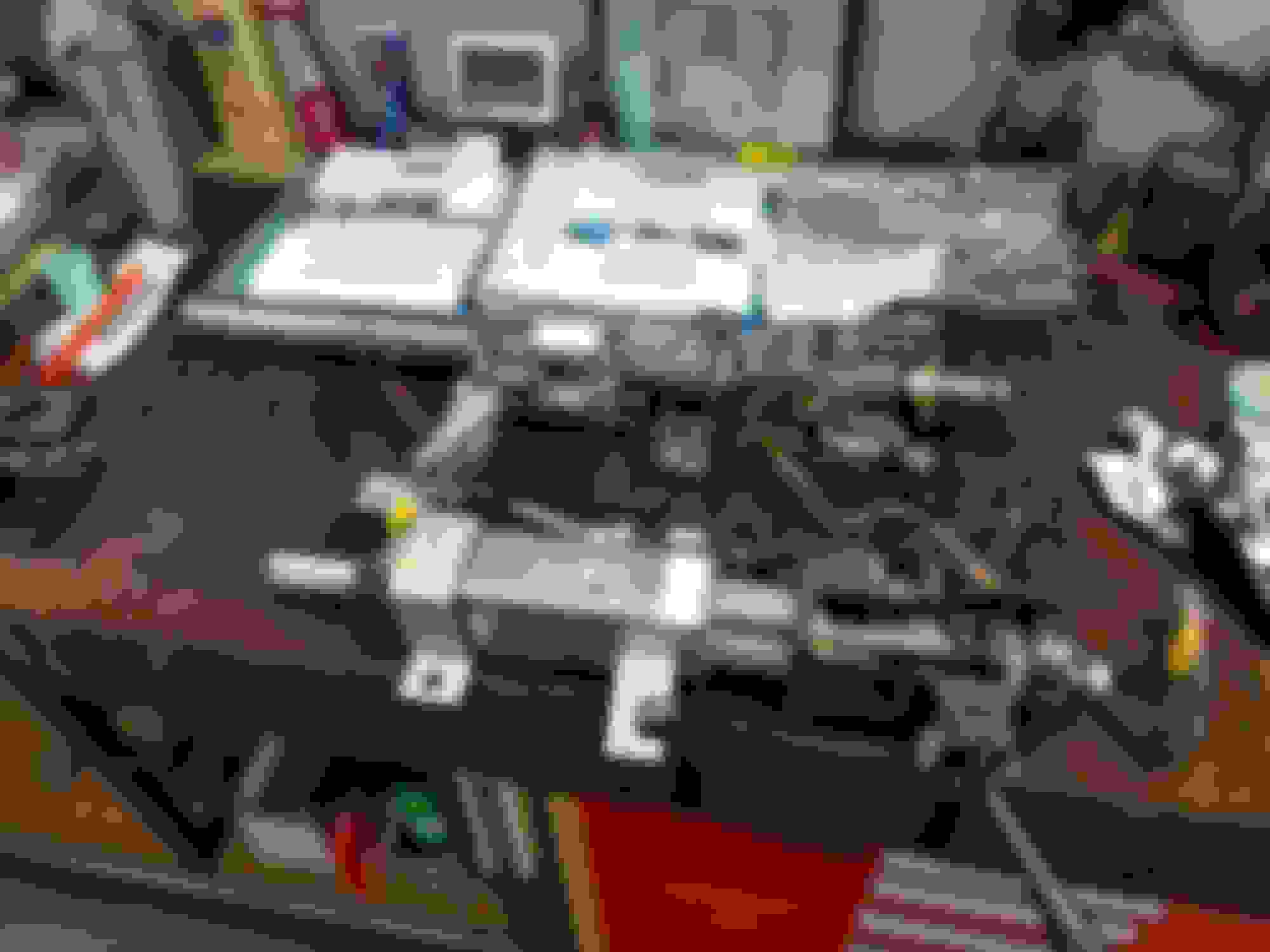
The lower column is out of a C6. The upper column is out of a C5. The C5 column has been stripped of its turn signal controls and the power telescope motor to make it easier to work with. This is what a C5 column looks like completely disassembled. Or at least 95% disassembled.
O.K., I have chosen a steering column. Now to get it mounted into the car so that it works with the stock clutch and brake pedals. The original column mounted to the same bracket used to hang the clutch and brake pedals. So I will start there. That bracket has four studs that go through the fire wall and mount to the vacuum booster for the brakes. Then at the front of that bracket there are two bolts that go up into the structural cross member that is part of the bird cage. This structural cross member goes through the center of the dash from the drivers side to the passenger side of the car. I needed to modify the clutch/brake pedal bracket so that the clutch and brake pedals are in the same position and location, but so I can also mount the new column to it. If you look at the previous post, you can see that on the new column at the front there is a large mounting flange. I wanted to utilize that flange also. I am not sure that I can really explain what I had to do to that bracket to make everything work. So I will itemize everything and post some pictures.
!. I cut the front of the original clutch/brake pedal bracket off and then added back to it what was needed to mount the new column to it.
2. There was a bracket at the end of the new column housing near the fire wall that was interfering and needed to be removed. Something different will be added later.
3. The new column housing tube was not long enough to reach and go through the firewall. So I bought some 2" tubing and added to its length.
4. There was a "steering wheel position sensor" at the end of the new column housing that I do not need. I got rid of that.
The hard part with everything listed above was updating the clutch/brake pedal bracket. It just took a little time to get it right.
I cut the front of original clutch/brake pedal bracket off in order to create my new steering column mounting points. I also had to trim a little off the side in order to clear the power telescoping mechanism.
Here is an original clutch/brake pedal bracket next to my new one. I also added a third mounting point to this bracket in the car. It still has the four studs that go through the firewall. It still has the two bolts that go up and into the bottom of the structural cross member in the dash. But now it also had two bolts that go into the front of the structural cross member. The new bracket is currently in primer.
The bracket at the end of the new column housing needed to be cut off. Something different will be added later. I will need something to mount to my firewall.
I added 4" to the length of the new column housing. I think that when all is said and done that I will remove about 3" of this. I will also need to add a bearing to the end of it to support the steering shaft.
O.K., I got my bracket made and some of the modifications done, so now I can mount the column. At least part way anyway.
I mentioned in the last post that I added two more mounting screws to the bracket. I needed to dill holes for them in the structural cross member in the dash. I could have just used two bolts and nuts through a through hole, or I could have welded in nuts to the cross member and used two bolts. Instead, I drilled the two holes and installed two steel threaded rivets into the cross member. This makes everything easier to install and I didn't have to try to get the welder up in there.
I was able to get the new column in and mounted. I am very happy with everything. The new column clears both the clutch and the brake pedal. It clears the brake light switch. It clears the parking brake lever. It clears the windshield wiper arm in the dash. I will be building a custom gauge cluster, so I am good there. There is about 2" of telescoping movement and lots of tilt movement both up and down. I put the dash in the car to help me position the columns final position. The columns housing extends all the way out through the firewall. In a future post I will trim the housing down, install a bearing and seal in the end, and fabricate a bracket for the housing to securely mount the column to the firewall.
This is the structural cross member that goes through the dash. The red arrows point to the two steel rivet nuts that I added for mounting the column/pedal bracket.
Here my new bracket is installed. You can see the clutch and brake pedals hanging there.
Here the new column is in. I still need to fabricate the mounting at the firewall.
I might use the stock wheel. I have the blown airbag. I figured that both the wheel and airbag could be recovered to match my interior. I am also considering an after market wheel. I think that I might like one of the wheels that has the flat bottom on the hand grip portion. This would give even more leg room. Interesting fact. A C6 steering wheel will not fit on a C5 column and vice versa. The thread and spline sizes are different. I like the C6 steering wheel that I have better than the C5, but it will not work.
Well I pulled the body back off the car. I wanted to pull all those plywood molds out from under the car before I went any further. They didn't just fall off, they were stuck on a little. But a little tapping and they popped off.
I still need to finish the driveshaft tunnel back near the differential. I thought that it might be easier to work on that with the body off the car. I need to get under the car to form some stuff up. If I hadn't removed the body, the chassis would have been in the way.
Here is what my molds looked like under the car and then what it looks like after they were removed.
- - This turned out very nice. A little sanding and some paint and no one will very know.
Well over a year ago I had posted about using some power seat bases out of a Volvo and adapting them to my 1969 seats. The 69 seats are what I am going to use in the 1965 corvette. They have higher backs than the stock 1965 seats. Since then I have been researching a way to add power recline to those same seats. The reason for this was just to simply be able to adjust the angle that your back was at. Obviously I am not going to fully recline and take a nap in the 1965 corvette. The stock 1969 seats seemed to lay back more than I would like. At first I thought that it might be because the rubber stops on the seat backs were worn out. I replaced them, but the seat still laid back more that I would like. So I started looking on Ebay. You can find a lot of useful stuff there. I found what I wanted finally and have made it work. I will cover what I did in the next couple of posts.
Below is how I left the seats a year ago with the Volvo seat base installed.
O.K., the first thing with the power recline was to find a power recline motor or hinge set up. Just like with the steering column, I tried or looked at a couple different things before deciding on a route to go.
First I had bought a couple of motors out of a Jeep Cherokee. They looked heavy duty, which they were. But they were also bigger than I thought from the pictures. The motor was going to be in the way of the seat base and was going to feel like you were sitting on a large hard egg somewhere under your butt. The other problem was that it was a one sided motor and hinge. meaning that this set up would have been good for moving the seat back, but to make it work I was going to have to come up with a new hinge system for the seat on my own. I decided to look for something else.
I found a set of hinges out of a Silverado / Sierra / Tahoe. This set up had two hinges. One with the motor and the other with a memory sensor which I might be able to make work on my drivers seat because the Volvo seat base for that side has memory. The two hinges are connected by a shaft between the two that makes them work together. This seemed to be the best set up and is what I went with.
This is the power recline motor out of the Jeep. It was larger than I expected and was not going to work well with my seats. This is the motor and hinge system out of the GM trucks. This system has both a left and right hinge, the motor, and a memory sensor.
The next step with the power seat recline was to figure out how to mount the hinges. Actually that was easy. When you look at the hinges that I bought they have two really nice bolt holes on each side of the pivot point. (4 bolt holes on each hinge) Next was where and how to mount them. The bottom part of the seat (the part you sit on) has a screw hole that was used for the original seat hinge. I used this as the forward bolt hole for the hinge. I bolted the front of the hinge on the seat frame using the existing bolt hole. I then used a "C" clamp to hold the rear of the hinge in place while I marked it. I drilled a hole a little over sized for a 5/16" screw. I used a nut and screw to mount the rear of the hinge in place. While secured I wire welded the nut to the back side of the seat frame. This way the hinge can be installed and removed without worrying about trying to hold the nut on the back side. I then repeated the process for the hinge on the other side.
This is the location of the pivot for the original seat hinge. There is already a nut welded on the back at this location. I used this location to locate and position my new hinges. Here both hinges have been bolted to the lower seat base. The arrow points to the original hinge pivot location. Notice the driveshaft that goes between the two hinges.
Attaching the back of the seat to the hinges was a little harder, but I more or less went through the same process. This time I did not have an existing hole in the seat back frame to start with so I had to use "C" clamps to hold the whole thing in place while I drilled four new holes. But before I could do that the lower cross brace on the seat back frame had to be removed. It was completely in the way of the recline motor.
These seat frames are all spot welded together. I could have use an abrasive wheel and just cut the brace out but it would be better to remove the brace in one complete piece so that I can weld it back in. Now to remove spot welds it you have never done so is not that bad. It is actually pretty easy and only took me a few minutes. It lightly sanded or ground the area with the spot welds so that they would show up better. I then center drilled each location. Then used a drill bit as big around as the weld itself to drill it out. Ounce they were drilled out the brace popped right off.
After the brace was out of the way I was able to complete the process of attaching the seat back frame to the hinges. The brace will go back in. I am going to modify it a little and re-weld it in a little higher up on the seat back frame.
Here you can see how I sanded a little on the frame and the spot welds showed right up. There are four welds on this side and six on the other side. Here the same four spot welds have been drilled out. I used a center drill first to get them started. And in this case I think I used a 3/8" drill bit to remove the spot weld completely. After the spot welds were removed, the lower brace popped right off. Here the seat back frame has been bolted to the hinges. On the left is my modified 8 way power 1969 corvette drivers seat. On the right is the future passenger seat and what I started out with about a year ago for the drivers side. The whole process will need to be repeated for the passenger side. Also because there is less space on the passenger side I am going to try to narrow that seat by one inch.
One last post on this subject and then I will probably be done with it for a while. I want to get the new zig zag springs for these seats and the foam so that I can sit on them and see how they feel. In its current location, the seat back frame is a little more forward compared to the original seat. Not much, about 3/4". I don't think that it will be an issue, but want to get the seat "sit-able" before I go any further. I will also start the process of redoing the passenger seat.
Below is the drivers seat the the original foams sitting on it. As you can see the same foam can probably be used on my seats. Something different will have to be done on the rear of the seat back and something will have to be done to dress up or cover up the hinges. I will also be removing all the extra brackets that were used for the original seat latches and etc on these seat frames. I wont be needing those.
The other thing that I wanted to mention about the recline hinges is that I ground off the stops. Most seats only recline forward a little and then recline all the way back. Reclining all the way back does me no good in this car. But I did want it to recline a lot further forward than they did with the stops. By removing the stops, I will be able to move the seat all the way forward and then recline the seat all the way forward. Being able to do this will give me the same access to the back of the car as the original seats did. I can weld new stops to the hinges later.
. The original foams sitting on the upgraded seat frames.
I will have to do something a little different with the seat back. I will need to dress these hinges up or cover them up somehow. And there may need to be some kind of shield around the recline motor, maybe extra foam on the back, or a different seat back cover than the original.
Just wanted to give an update. I finished up my driveshaft tunnel and have begun looking at body work. Overall the body looks really good, but while test fitting some parts that were never installed on the car, I have uncovered some issues. The previous owner had the body work done up to the current state. During that work things like the hood, headlight housings, and rear valance were never fit to the car. And as I have stated in the past, there is evidence that this car had been in some type of crash in its past. There was the bent frame that had to be dealt with. There is evidence under the car of diver side front fender repair. There is evidence of front nose repair. And there is evidence of rear driver side quarter panel repair. The repairs all look good, but I am afraid that these repairs have lead to other issues especially since they were all done on a bent frame.
I finished up the driveshaft tunnel. Pretty soon I am going to have to get itchy and start sanding. All this will need to be sanded and for sure a little more patch work done.
I started to fit my new hood. The original hood was never on this car. It did come with the car, but I wanted the big block hood. The gaps need some work. The top end of the hood near the windshield sits pretty well. The passenger side front corner near the headlight is a little high but has some shims that can be removed. The drivers side front near the headlight (near the fender repair) is where the problem is. It is about an 1/8" high, maybe a little more and there are no shims under that hinge. There is definitely something funny going on there that I am not sure what to do with yet. I also need to cut the holes in the hood for the vents. Those will really make it look cool.
I started to fit my headlight housings. These also were never on the car after or during body work by the previous owner. They look good in the picture, but both rub like crazy on both sides of the headlight housings. I am afraid that I may have to remove or take loose the headlight housing end plates and re-position them. There is just no gap there. I would have to remove all the fiberglass on the end plates to get good clearance. It almost appears that the end plates are not square. I am not going to get too crazy with anything until the body is bolted back down on the frame which is going to happen real soon now that the driveshaft tunnel is done. Notice this issue is near the repaired front fender and the repair near the nose.
Any input on the headlight housing end plate issue would be appreciated. I looked around on the forum but didn't find much.
The rear valance needs to be fit to the car. The drivers side end is not flush with the body. An issue near the repaired rear quarter panel. The passenger side end is not too bad but needs work. The strip under the passenger side quarter panel that the rear valance bolts to is busted loose and will need to be repaired. One of the threaded blocks that the valance screws to on the drivers side is stripped out and will need to be replaced. On the plus side, the tail lights seem to fit well.
I have been digging through boxes in the attic of the shop looking for stuff. I am a little worried about the body being finished on a bent frame. This car came with the original rear window and a new wind shield in a box. I pulled them both out and set them in place to check how well they fit. They both looked good as far as I could tell. Just afraid that something might be twisted. I also found all the trim for both windows. That is good, because I looked at the prices for replacement trim, and you are looking at about a grand. It all looks pretty dirty. But since I believe that it is all stainless steel, it should all polish up really nice. I only found a couple off little dings in all of it. Below is a picture of the rear window trim.
Below is a picture of the fully glassed drive shaft tunnel from underneath the car. I have learned that less resin is better, but it is also harder to apply. You want just enough resin to soak the fiberglass matting. When you remove the molds, the mold side is very transparent looking and smooth. It really looks like it is all resin, but it is not. I bought pretty thick matting. It was "1.5 ounce" and I applied four layers. I drilled some small holes to to check the finished thickness in a few spots and I am a good 1/8" thick which is what the rest of the car. So I don't think that I will add any more. I plan on sanding this all down smooth and rounding the corners. I will then repair any thin spots that I do find or I will add more to reinforce any spots that I think need it. I will probably buy some fiberglass infused body filler to clean the surfaces up. I saw on a hot rod show that using the fiberglass body filler on fiberglass was better than regular filler because it uses the same resin and bonds better to the fiberglass surface. They said that it was also harder to use. I think that it is tougher to sand and may require more applications to get it smooth. I will be doing all this on the inside and outside of the tunnel. I also read here on the forum that fiberglass really needs to be cured under heat for a while after it has hardened before paint. That means either in the sun or with a heat lamp(s). Face it, the car is not going to sit outside, so I think I will invest in a heat lamp for in the shop to put on it every once and a while. FYI, even with the heat lamp they were talking about hours.
FYI, I have not done very much body work before but am going to give it a go. I think that I am just **** enough to give it a good shot. For example, I am not a professional drywall person either. But I do it. Where is takes a professional crew about there days to do, it takes me 3-4 weeks. I get it done and it actually looks professional.
 12-02-2018, 02:46 PM


 Dennis