When you click on links to various merchants on this site and make a purchase, this can result in this site earning a commission. Affiliate programs and affiliations include, but are not limited to, the eBay Partner Network.
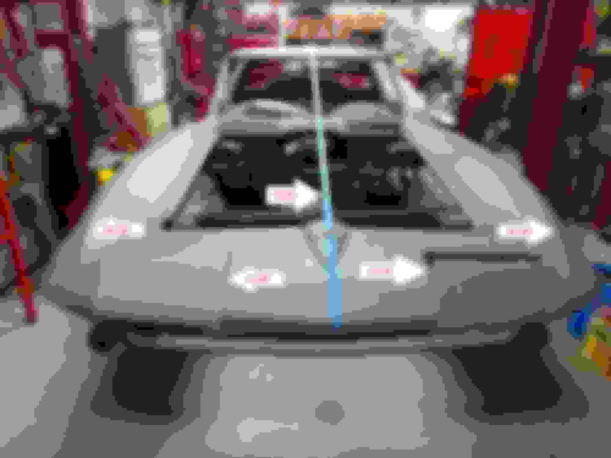
O.K., I have been looking at the front end of the car and taking a few measurements. I put a piece of tape down the center for reference. (My laser is in Wisconsin at my brothers house. When I get it back, I will measure again) From a rough look, everything looks pretty close. The inner headlight housings measure exactly 8-5/8" each. Measuring from center, straight across the front of the hood opening, to the top ridge of the front fenders measures as follows. Drivers side fender, 28-5/8". Passenger side fender, 28-7/8". A 1/4" different. Not noticeable. I am not sure what it should be, so I will have to look into it.
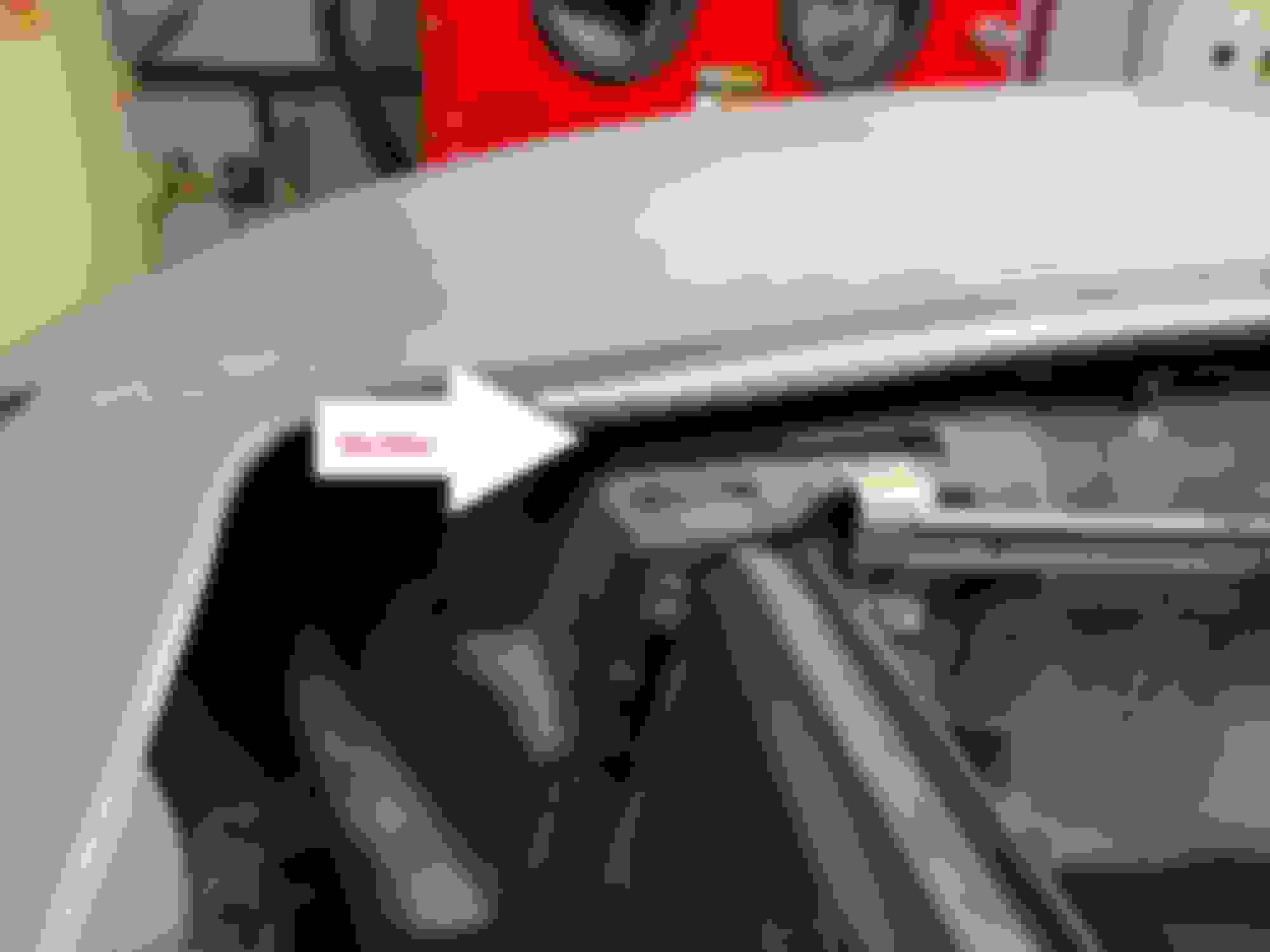
Looking at the locations for the hood hinges on the driver side and passenger side fenders, there are noticeable differences. The pictures below show how the drivers side hinge mounting area is higher and filled with a lot of body filler. The passenger side hinge needs shims under it to get the hood to the right level. On the drivers side, the hinge sat to high without shims. Comparing the two sides with no shims you can see that the drivers side is higher.
The drivers side fender shows damage that has been repaired. I think that it has a new inner fender. The inner fender also seems to be to far inboard which is also causing problems with the hood hinge.
This is the damage to the inside of the drivers side fender. The bonding strip is broken and was just pushed back in place and patched.
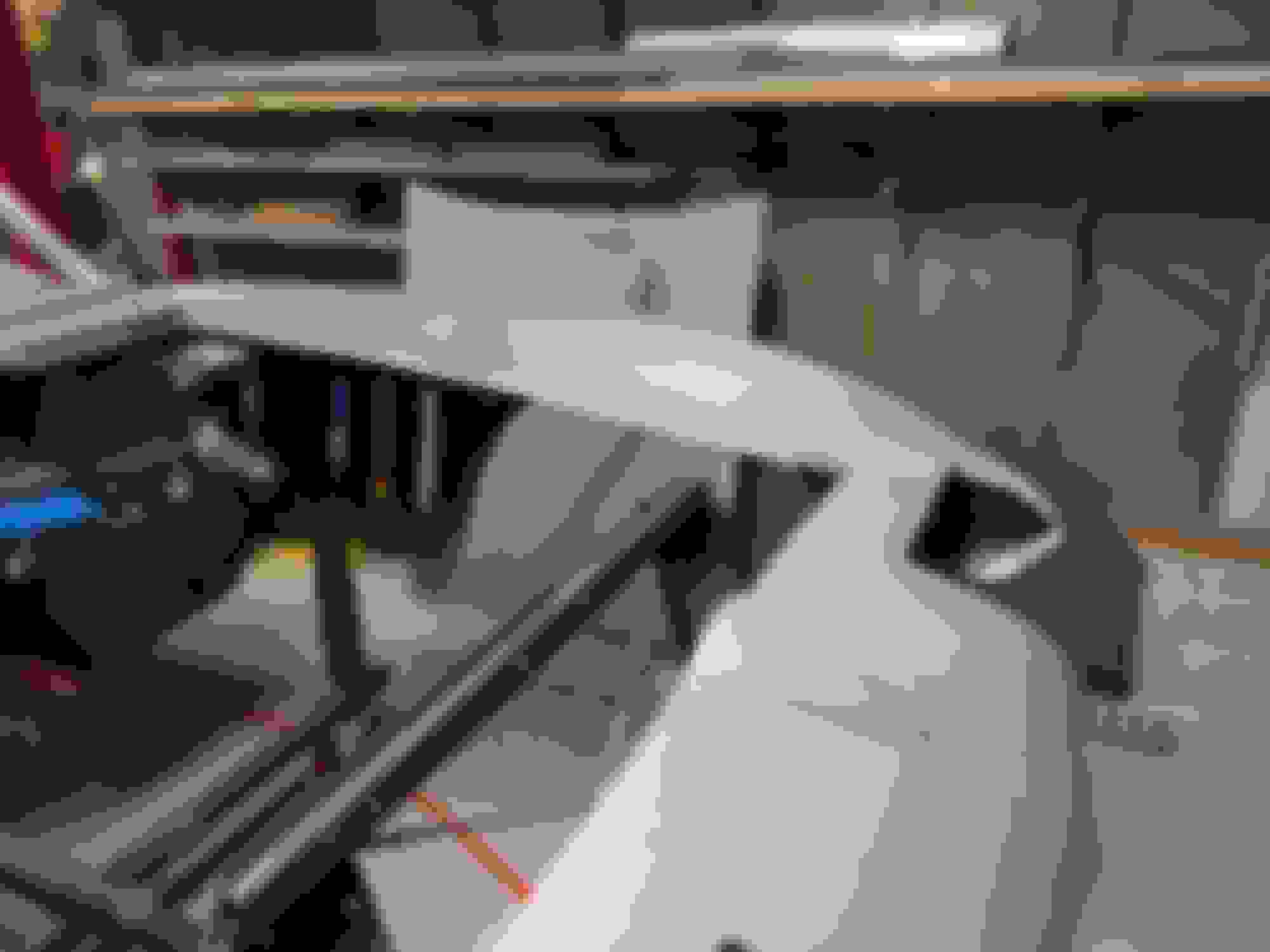
This is the area where the out fender meets the inner fender. A huge fiberglass patch. I am not sure if there is damage to the fender there, or if they were just trying to bond the inner to the outer. On the other side of this is where all the filler is. Also the hood hinge brace is to low. It is not tight against the top of the inner fender. The weld nuts are also missing from it. This will need to be replaced.
This is why I think that the inner fender is to far in board. I can stick my fingers all the way through there. You can't do that on the passenger side. If this was moved to the outside, the alignment at the hood hinge would be better.
The nose on this car was caved in. The upper and low nose panels were both broken. The bonding strip for the two panels was of coarse broken also. Again, all three pieces were pushed back into place and patched together. The header bar seems fine except there are two broken bolts and one missing weld nut. The missing weld nut is for one of the headlight motor supports. And get this, the two broken bolts are supposed to be holding the outer headlight end plates. There is something up with all four headlight end plates. They are either not square or bent.
This is the back/under side of the nose. All busted up and roughly repaired.
This is the outside end plate for the drivers side headlight. As you can see, one of the bolts that holds it in place is missing. I can feel the weld nut up there and it doesn't feel like a broken bolt inside it. The bolt just was not put in. So the question is. Is that bracket that far off with alignment or bent like crazy. Either way it certainly is a big part of the issues that I have with installing the headlight housings. I also noticed from my picture here that this bracket has three holes?????
This is the outside end plate for the passenger side headlight. This end plate is not as bad as the drivers side, but it still is not completely bolted down. This one the bolt is broken off. I can feel the weld nut with part of the bolt sticking up through in the header bar.
I am going to be out of town for a couple of weeks after today so nothing will be getting done for a while. I think I have a game plan for when I get back though. Since there are so many issues with the nose section and the headlights on this car, I have decided to redo it. I am going to remove the upper and lower nose panels along with all four headlight end plates. They will all be replaced with new parts including the bonding strip. Then I am going to try to just remove the drivers side inner fender and see if it can be re-positioned to fix the hood hinge issues.
I am going to start with this plan. If needed I will replace the drivers side fender. I don't want to go that far unless I have to. The current fender looks pretty good on the outside. And if I have to replace it that means having to get into the hood surround and fixing or redoing drivers side door gaps.
First I am going to clean up all that new fiberglass for the driveshaft tunnel on the bottom. When that is done I will remove the panels talked about above. It will be easier to remove those with the body off the car. When those are removed I will place the body back on the frame and start looking at repairs. At that time I will also place the doors back on with latches so that I can make sure everything is aligned and functioning as I go.
I have been making some progress and have ordered some parts. I removed the left side front inner fender and to my surprise it kind of popped right out. I didn't think that was a good sign. The front and rear edges that mate to the outer fender were very lightly glued in with fiberglass risen only. The top edge I did have to cut. The top edge that attaches to the bottom of the hood surround had been butchered up pretty badly. That is why there was the big fiberglass patch on the under side.
This is what I think happened. The first problem was that they did all the body work on a bent frame. The drivers side of the frame was bent up. Since the frame was up on that side, they butchered up the top of the inner fender so that it would fit in the shorter space between the frame and bottom of the hood surround. This moved the mounting point for the hood hinge up which made the hood sit to high. The second problem was that they also did all this work without ever having the hood or headlights installed.
The drivers side inner fender could not be re-used since it had been butchered up so I ordered a new one. Now two things. Since the drivers side was not bonded in very well and since there was a good chance that it would have busted lose in the future with any body flexing, I decided to take a closer look at the passenger side. I planned on ordering a press molded diver side inner fender. After looking closer, I realized that the current inner fenders were hand laid parts. That was it. I have to replace both inner fenders so that they match. And it was a good idea. The passenger side inner fender was not bonded in much better than the drivers side.
Both inner fenders have been ordered and are on there way.
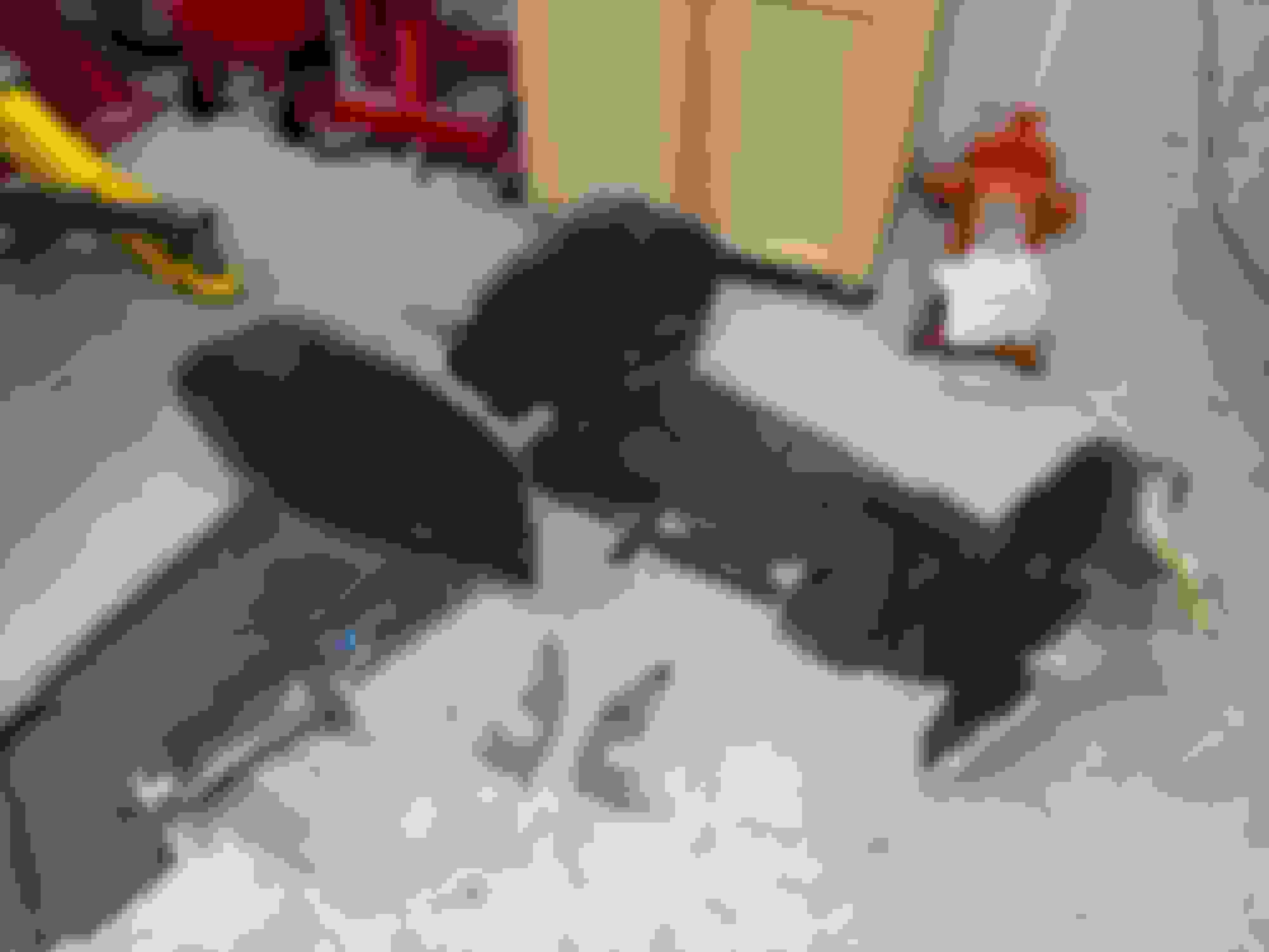
Here are both inner fenders pulled out along with both outer head light flanges. I pulled those out now while I had the extra space. Here you can see how the drivers side inner fender was cut up. The mounting flange at the top is gone. The passenger side with no inner fender and the outer headlight flange removed. The drivers side with no inner fender and the outer headlight flange removed.
I'm not 100% sure you can do everything your doing with this body not being mounted on the frame. For sure do not bond the inner wheel well to the upper surround or you will have fitment problems with the hood.
I did install the door hinges into the birdcage. The bottom two went right in. But for the life of me, I couldn't get the top two in or figure out how I even got them out. I must have forced them out when I did remove them. I know that I was the one that removed them because the doors were on the car when I bought it. There was just enough interference that I could not get them in without gouging what would be paint later. After reading a couple of threads on the forum here, it sounded like this might be a common issue. I ended up using the die grinder and clearancing the upper corner of the pocket opening. A little grinding and now I can slip them in and out. I have to be careful, and when the car is painted, I will have to have everything taped up.
I wanted to get the doors back on for the body work. Later the hinges will come back out and be painted the same color as the car.
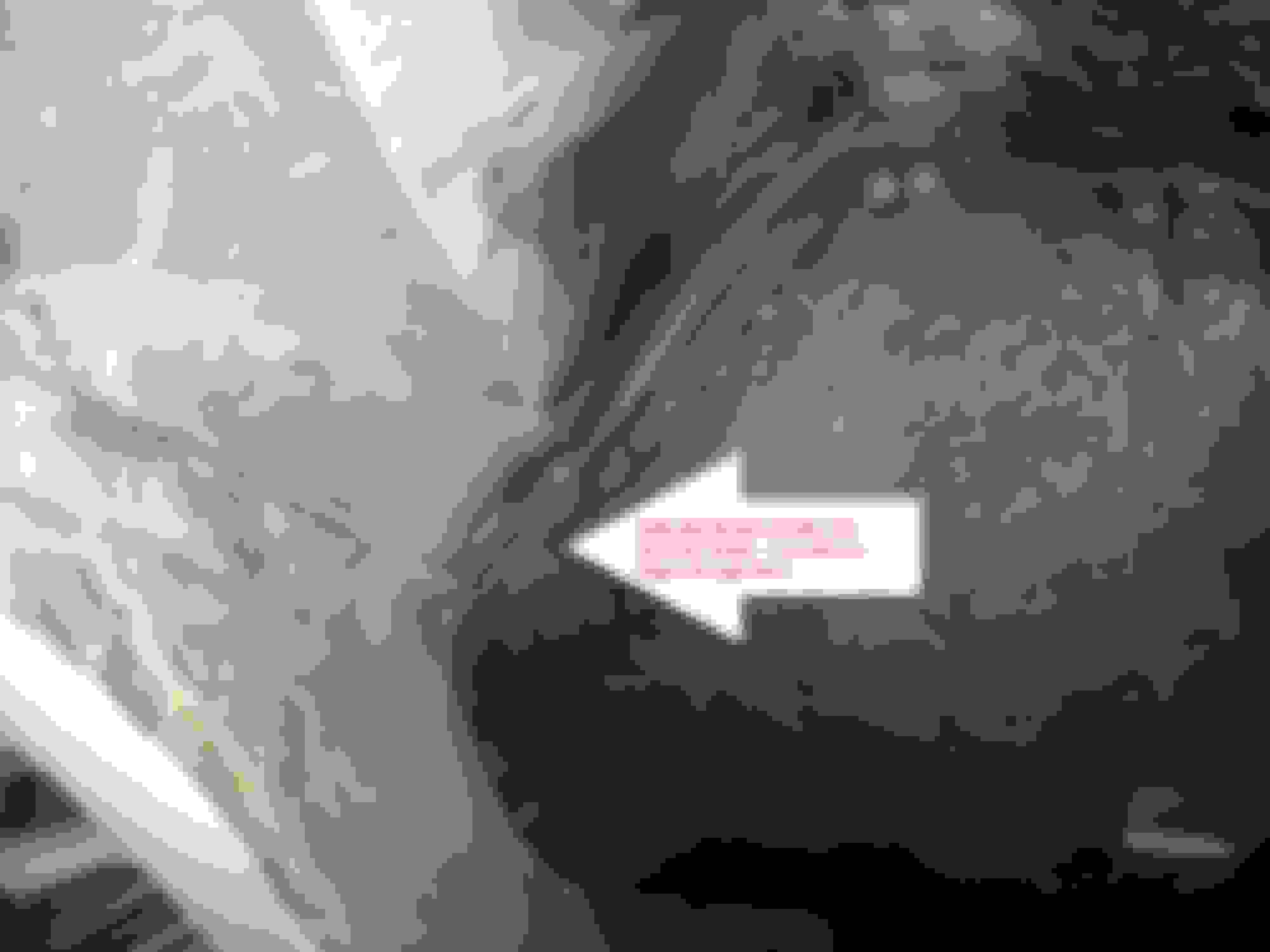
The arrow points to the corner that I modified. It was originally a 45 degree corner and I ground it out to a radius.
I'm not 100% sure you can do everything your doing with this body not being mounted on the frame. For sure do not bond the inner wheel well to the upper surround or you will have fitment problems with the hood.
I will defer to the forum body experts.
Oh no, don't worry. I only removed the inner fenders while the body was on my cart because I had more space to work. The body is getting ready to go back on the frame as we speak. Nothing will be replaced or bonded until the body is back on the frame.
So while the body is still on my cart, I wanted to grind and sand off all the large deposits of fiberglass risen that were left behind after removing the inner fenders and the outer headlight flanges. There was a rather large lump on the drivers side. When they were attempting to bond the inner fender in on that side, they created a dam with tape and poured a whole bunch of risen in.
Yuck
I also cleaned up all the other ridges left behind and in around where I removed the outer headlight flanges. A little more sanding and I think that I will be ready to set the body back on the frame. When the new inner fenders arrive I will be able to start the process of fitting them.
If you can see up in there. There is a rather large lump of fiberglass risen. I wish that I had gotten a better picture of this. Here I have ground and sanded the risen lump all out. I may have to do some more sanding when I am fitting the inner fender in. But removing the bulk of it now was much easier.
While I have been waiting for fiberglass parts to show up there were a few things that needed to be finished up on the chassis. One of which is the fuel system. I have had most of it done for a while. You have been able to see the tank in the pictures for a long time but I hadn't talked about it because I wasn't completely done. I needed to run a return line and hadn't done it because I wasn't sure where exactly to run it until I had the body back on and could look at clearances for routing. Since the body was back off, this was a good opportunity to complete that line.
First, if you don't have a tubing straightner and plan on making your own lines, then you should get one. The one I bought was about $125. Not the cheapest and not the most expensive, but in the middle. It was made in China but the quality was good and it worked awesome. It made a huge difference in making a nice line.
I bought a Tanks Inc internal pump tank and a Walbro fuel pump last year. I am using a Fuelab fuel filter and plan on using the matching regulator when it is time. The regulator will be mounted on the firewall somewhere.
I had already ran the stock 3/8" big block fuel line (stainless steel) and most of the second line follows along with it until it gets to the rear kickup on that side. Then it goes along the inside of the frame back to the tank. The second line is also stainless steel. I am using the stock line as the supply line and the new line as the return line. I used AN-6 fittings and stainless steel braided hose to tie it all together
I spent about two days bending up this line and getting it right. I had to laugh because the same day that I took this picture, FACTOID was doing the same thing with his project and posted what I can only describe as the exact same picture. The front half of the lines run along side of each other. I turned and terminated both lines just behind and below the battery tray. This was a change to the stock line as it originally went further up on the frame towards the front of the engine. The new line makes a couple of 90 degree turns at the rear kickup and goes along the inside of the frame similar to the brakeline routing on the other side. The new line runs along the outside of the frame while the stock line is still inside the frame. You can see the fuel filter mounted to the cross member and all the SS braided lines that tie it all together.
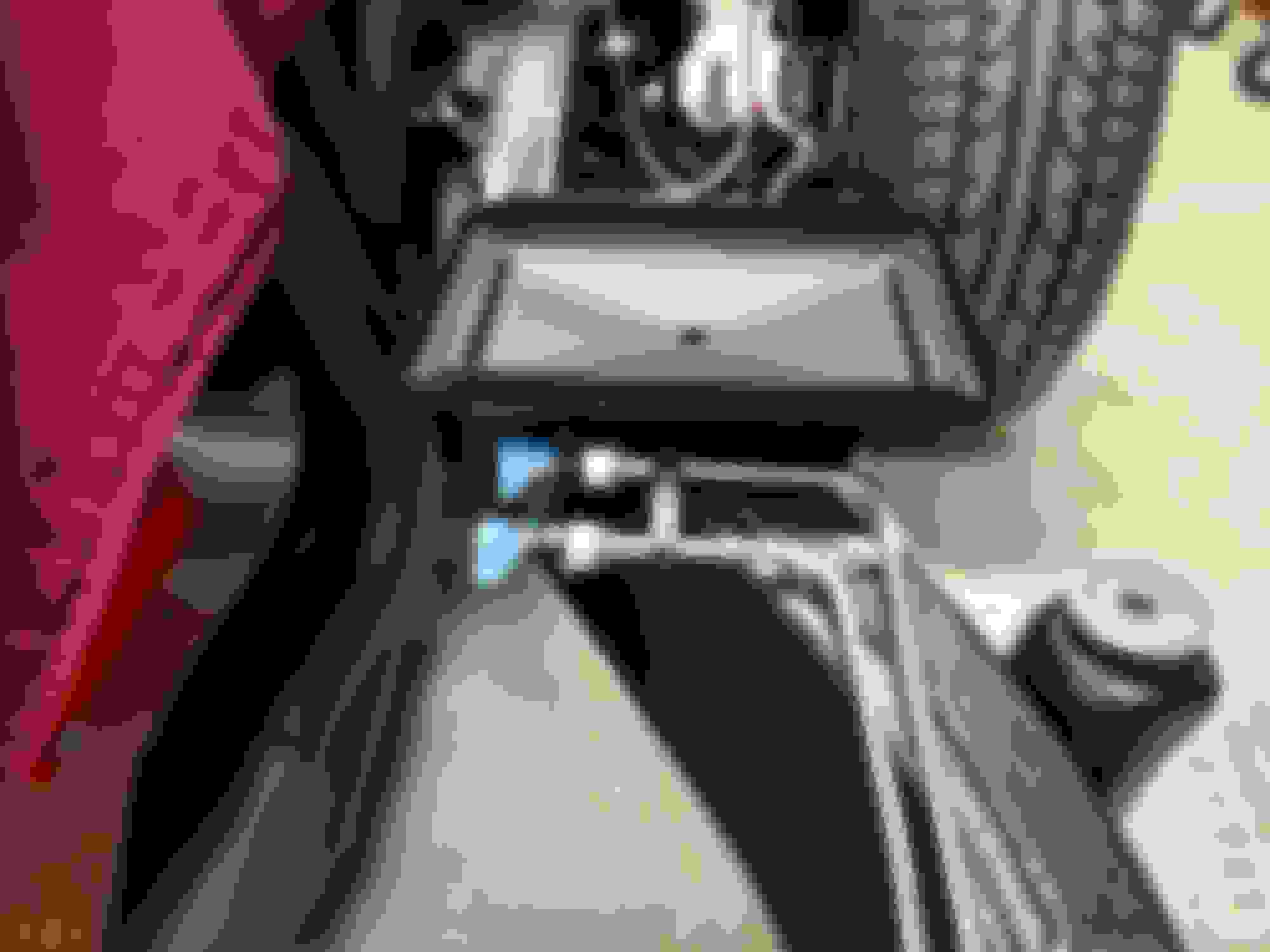
Where the original line exits the frame I have a 150 degree fitting that sends the hose back to the fuel filter. This is where I mounted my vent - rollover valve. I have read that it is a good idea to use these when running a system with a return line. If your cap is vented well that works also. I wasn't sure about these older caps so went ahead and used the vent. There is plenty of room in this location and the valve is well above the fuel level. I made a bracket that sits on the fuel pump flange. I replaced two of the flange screws with threaded studs and ran two nuts down to tighten down the flange. The bracket sits on top of those two nuts with two washers and two nuts installed next to hold the bracket. FYI, I powder coated my cap and filler neck that gloss black. This is a better look at how and where both lines end in the engine compartment.
I also have the Tanks Powdercoated tank, Walbro intank pump and rollover valve. When I ordered my tank and various components from Summit, they ended up sending me a consolidated kit with a significantly lower price and the instructions were for the Holley Sniper set up (who knew?). I epoxied a bracket I made to the body as high as I could go for the vent rollover valve. I hope to get all of that installed next weekend once I paint the driver side of the frame. My fuel filter will be in the engine compartment. Isn’t working with stainless lines fun? Do you plan on pressure testing your lines before buttoning it all up.
I got my two inner fenders. For the most part they look good. Nice press molded parts except. The left side looks like it might have been a little deformed coming out of the mold. I am talking to the manufacturer to figure out what is going on. The flange at the top that would be bonded to the bottom of the hood surround is twisted and looks like it sagged on the wheel side. I realize that I may have to do a little more grinding and sanding, but this would require some cutting and rebuilding.
The right side I haven't been able to get completely in yet. There is another large lump of old fiberglass risen that needs to be ground out before I can.
I also have the Tanks Powdercoated tank, Walbro intank pump and rollover valve. When I ordered my tank and various components from Summit, they ended up sending me a consolidated kit with a significantly lower price and the instructions were for the Holley Sniper set up (who knew?). I epoxied a bracket I made to the body as high as I could go for the vent rollover valve. I hope to get all of that installed next weekend once I paint the driver side of the frame. My fuel filter will be in the engine compartment. Isn�t working with stainless lines fun? Do you plan on pressure testing your lines before buttoning it all up.
Keep up the great work!
Mark
Funny, I was just talking to my wife about pressure testing them. I just haven't decided how to go about it yet. One of the fittings on top of the tank is a swivel and it seems a little loose. I am worried about it. I would rather test it now and not have to tear the tank out later.
And stainless steel is not as easy to bend as one might think. I need a better tubing bender! Something with longer handles and more leverage.
The easiest way to test the stainless lines, the flex lines in the engine bay and your two flex lines to the tank is to connect the two lines in the engine bay with a double male AN connector. Then use a AN fuel gauge fitting (double male with a 1/8 npt female made for a fuel gauge to screw in to) and install a 1/8 to 1/4 npt adapter and an air tool quick disconnect fitting on to that adapter (use sealant on the npt fittings). All these fittings are less than $20. Now connect your air compressor fully charged, but not running with the output regulator set to zero. Slowly increase the output pressure to 100 psi listening for leaks. If you hear none, pour some soapy water over every joint looking for bubbles. The whole thing will take you 15 minutes, but give you huge piece of mind. Oh, and the reason you can’t reliably let it sit and check for bleed down is that the quick disconnects are notoriously leaky making it difficult to assess. I’ll post mine next weekend when I get home (travel this week). Best of luck!
 01-01-2019, 10:50 AM