[C2] Overflow Hose Routing
#1
Safety Car


Thread Starter
Member Since: Apr 2013
Location: Arlington TX
Posts: 4,833
Received 929 Likes
on
531 Posts
2023 Restomod of the Year Finalist
2023 C1 of the Year Finalist - Unmodified

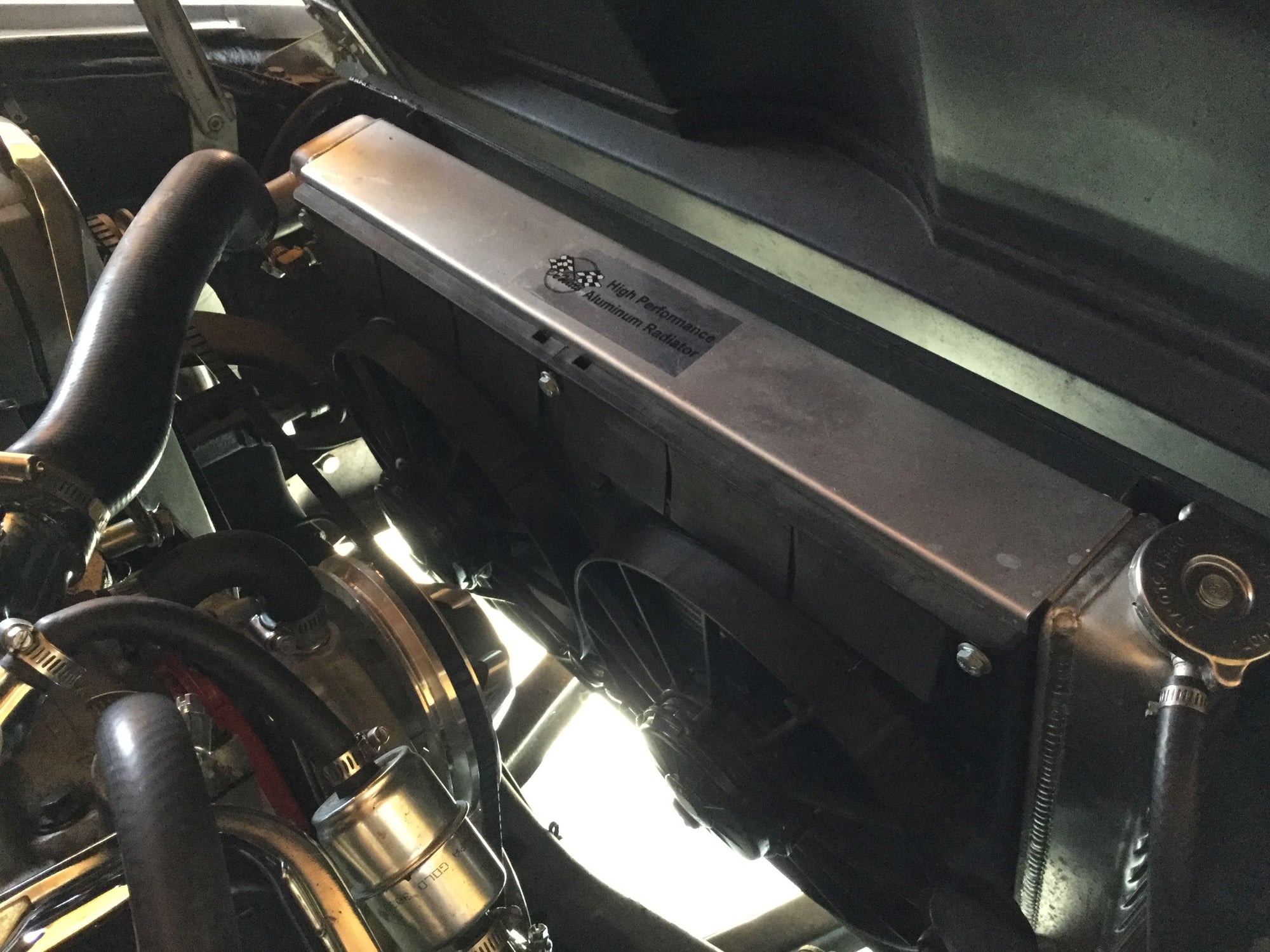
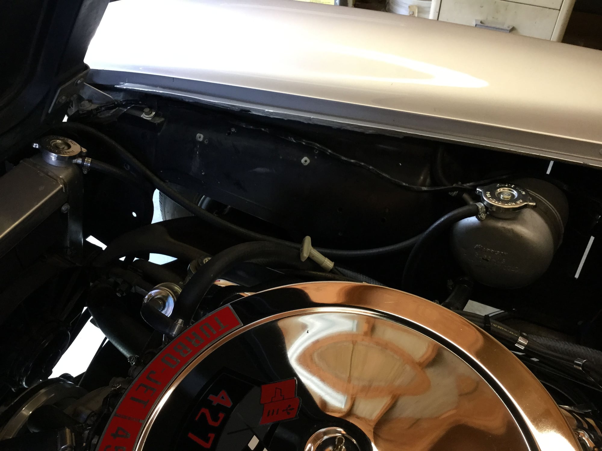
I was looking over my overflow hose routing and doesnít look right to me. Just got this 65 with a Dewitt radiator and the overflow hose runs downward and out and not to the expansion tank. I can find diagrams of heater hose routing but not tank routing. Anyone have one?
#2
Drifting


Got pictures? I'm guessing the engine is a small block, since I believe you're saying you have the tank inside the right fender. But do you have a small block radiator with no filler neck or a big block radiator with a filler neck? Where is the outlet tube on the filler neck on the tank connected, if anywhere?
#3
Le Mans Master


If this is for your '65 and it's a small block, here are a couple of pictures from my '67...same routing for your '65. Note the hose runs BEHIND the hood support and is held in place there by one of the three tie straps that secure the hose to the inner fender well. Hope this helps.
Last edited by leif.anderson93; 11-06-2017 at 03:12 PM.
The following users liked this post:
USMC 0802 (11-06-2017)
#5
Le Mans Master


You have a very unusual configuration there on your modified 65. When you are using a BB copper or aluminum radiator with side reservoir tanks like you are, you normally will not also have a remote expansion tank. The overflow hose exiting under the radiator cap to the ground acts as the relief valve. You have that, but you also have an expansion tank with another overflow hose that runs from the drivers side reservoir tank all the way around through the top of the core support. Nothing about that set up is factory-like. But, if you like it that way, that is all that matters. I don't believe it is serving any purpose except perhaps to give you an extra quart or so of coolant in your system.
#6
Safety Car


Thread Starter
Member Since: Apr 2013
Location: Arlington TX
Posts: 4,833
Received 929 Likes
on
531 Posts
2023 Restomod of the Year Finalist
2023 C1 of the Year Finalist - Unmodified

You have a very unusual configuration there on your modified 65. When you are using a BB copper or aluminum radiator with side reservoir tanks like you are, you normally will not also have a remote expansion tank. The overflow hose exiting under the radiator cap to the ground acts as the relief valve. You have that, but you also have an expansion tank with another overflow hose that runs from the drivers side reservoir tank all the way around through the top of the core support. Nothing about that set up is factory-like. But, if you like it that way, that is all that matters. I don't believe it is serving any purpose except perhaps to give you an extra quart or so of coolant in your system.
#7
Former Vendor
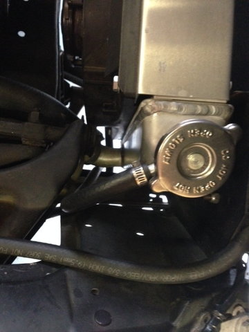
You have a radiator that we designed to eliminate the surge tank. The connection on the radiator is the pressure cap vent port. This should go directly to the ground. Since it is run to a pressurize tank, that makes that cap non-functional.
The following users liked this post:
59BlueSilver (11-06-2017)
#8
Safety Car


Thread Starter
Member Since: Apr 2013
Location: Arlington TX
Posts: 4,833
Received 929 Likes
on
531 Posts
2023 Restomod of the Year Finalist
2023 C1 of the Year Finalist - Unmodified

That does go directly to ground. Then what is the purpose of the fitting on the left side, and where should it go?
#9
Team Owner


Member Since: Feb 2003
Location: Sitting in his Nowhere land Hanover Pa
Posts: 49,002
Received 6,943 Likes
on
4,782 Posts
2015 C2 of Year Finalist

The following users liked this post:
59BlueSilver (11-06-2017)
#11
Team Owner


Member Since: Feb 2003
Location: Sitting in his Nowhere land Hanover Pa
Posts: 49,002
Received 6,943 Likes
on
4,782 Posts
2015 C2 of Year Finalist

#12
Former Vendor
#14
Former Vendor
#15
Safety Car


Thread Starter
Member Since: Apr 2013
Location: Arlington TX
Posts: 4,833
Received 929 Likes
on
531 Posts
2023 Restomod of the Year Finalist
2023 C1 of the Year Finalist - Unmodified

It seems dorky to me to have hoses running all over the place plus a non-functional tank, I like a clean engine bay. To get back to my original question, does this setup have anything to do with me having to add a cup of coolant after a drive?
#16
Drifting


If it was me, I'd turn the expansion tank, or surge tank, or whatever you want to call it, into a coolant recovery tank like what is on the modern cars. Run the overflow from the radiator into the top of the tank, and modify the rest of the tank so it works as a coolant recovery/return. Making it a closed system. Then, if it continues to lose coolant, you'll know it's disappearing inside the engine somehow or out one of the radiator or heater hoses. Not through the radiator overflow.
#17
Safety Car


Thread Starter
Member Since: Apr 2013
Location: Arlington TX
Posts: 4,833
Received 929 Likes
on
531 Posts
2023 Restomod of the Year Finalist
2023 C1 of the Year Finalist - Unmodified

If it was me, I'd turn the expansion tank, or surge tank, or whatever you want to call it, into a coolant recovery tank like what is on the modern cars. Run the overflow from the radiator into the top of the tank, and modify the rest of the tank so it works as a coolant recovery/return. Making it a closed system. Then, if it continues to lose coolant, you'll know it's disappearing inside the engine somehow or out one of the radiator or heater hoses. Not through the radiator overflow.
#18
Safety Car


Thread Starter
Member Since: Apr 2013
Location: Arlington TX
Posts: 4,833
Received 929 Likes
on
531 Posts
2023 Restomod of the Year Finalist
2023 C1 of the Year Finalist - Unmodified

If it was me, I'd turn the expansion tank, or surge tank, or whatever you want to call it, into a coolant recovery tank like what is on the modern cars. Run the overflow from the radiator into the top of the tank, and modify the rest of the tank so it works as a coolant recovery/return. Making it a closed system. Then, if it continues to lose coolant, you'll know it's disappearing inside the engine somehow or out one of the radiator or heater hoses. Not through the radiator overflow.


