When you click on links to various merchants on this site and make a purchase, this can result in this site earning a commission. Affiliate programs and affiliations include, but are not limited to, the eBay Partner Network.
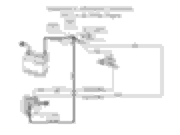
Two years ago I converted my 59 from generator to alternator, as some of you might remember. With help from you guys, I wired it per the diagram below and it runs great.
Now I need to do my 65 because the PO wired it for one wire. and I want to upgrade the amps anyway, but I don't want to get under the dash and mess with the ignition switch if at all possible, no room.
I already have an ign. wire to terminal B, so can't I just run the white field wire to it? Accomplishes the same thing, right?
Also, terminal A goes straight to the battery., so why is there a wire going from terminal A to the BAT. terminal on the ignition switch?
As no one else has stepped forward, let me ask a question or two. First, what does the wiring for your 1959 have to do with how you want to do the wiring for your 1965? If your 1965 has a one wire alternator and you'd simply like one with higher output, why not get a new one wire alternator? If you want to go with the older style alternator, do you want to go back to completely stock?
As no one else has stepped forward, let me ask a question or two. First, what does the wiring for your 1959 have to do with how you want to do the wiring for your 1965? If your 1965 has a one wire alternator and you'd simply like one with higher output, why not get a new one wire alternator? If you want to go with the older style alternator, do you want to go back to completely stock?
Thanks for your questions. I simply don�t care for one wire alternators and not stock, meaning this alternator has an internal regulator. None other wiring exists.
What follows assumes your 65 is like my 63, but that is an assumption, not a statement. ... When I replaced my stock alternator/remote voltage regulator with a one-wire altternator, all of the changes occured in the engine compartment and did not involve the ignition switch. Essentially, all the wires that used to run between the original alternator, voltage regulator and horn buss were replaced with an alternator that grounded to the engine through its mount, and a single wire to the horn buss. If you want to reverse that process you'll need to get the remote voltage regulator and wire the old style alternator and voltage regulator together per the wiring diagram in the shop manual. Then, as it shows in the manual, there will be one more wire from the voltage regulator to the horn buss.
I am confused, are you putting an internally regulated (not stock) alt on your '65 or an external (stock appearing) regulated alt?
As to one of your questions: different voltages exist at different parts of the wiring harness, due to load and line loss, so sensing voltage at say the ignition switch, or horn relay will give the alternator a better idea of how much current it needs to put out vs sensing just battery voltage.
What follows assumes your 65 is like my 63, but that is an assumption, not a statement. ... When I replaced my stock alternator/remote voltage regulator with a one-wire altternator, all of the changes occured in the engine compartment and did not involve the ignition switch. Essentially, all the wires that used to run between the original alternator, voltage regulator and horn buss were replaced with an alternator that grounded to the engine through its mount, and a single wire to the horn buss. If you want to reverse that process you'll need to get the remote voltage regulator and wire the old style alternator and voltage regulator together per the wiring diagram in the shop manual. Then, as it shows in the manual, there will be one more wire from the voltage regulator to the horn buss.
I agree, I don�t think I have to mess with the ignition switch. Thanks!
I am confused, are you putting an internally regulated (not stock) alt on your '65 or an external (stock appearing) regulated alt?
As to one of your questions: different voltages exist at different parts of the wiring harness, due to load and line loss, so sensing voltage at say the ignition switch, or horn relay will give the alternator a better idea of how much current it needs to put out vs sensing just battery voltage.
Doug
Yes, it�s internally regulated. So you�re saying it�s better to send the sensing wire to the horn relay?
I used a Powermaster externally regulated 100 amp alternator that is a direct bolt in for the original alt. It works great and still looks like the OEM setup for not a lot of money.
 01-21-2018, 11:00 AM