When you click on links to various merchants on this site and make a purchase, this can result in this site earning a commission. Affiliate programs and affiliations include, but are not limited to, the eBay Partner Network.
Doing some work on the 61 frame off today. I installed the clutch linkage and the angle between the rod going to the pressure plate and the clutch pedal arm looks incorrect. I expect the arm going to the clutch arm to be pointing down at the ground rather than than forward. Just for reference I adjusted the rod to have the clutch arm so that the throwout bearing is just starting to touch the pressure plate. I know these arms press on with serrations is it possible one is installed incorrectly?
but, if you look at the angle between the 2 arms they appear to reflect the AIM; the outside arm is rotated too far back and the pushrod to the throwout fork is way too long to let the inner arm rotate back to where it should be.
but, if you look at the angle between the 2 arms they appear to reflect the AIM; the outside arm is rotated too far back and the pushrod to the throwout fork is way too long to let the inner arm rotate back to where it should be.
Bill
I adjusted the length and shortened the rod but it still seems wrong and the amount of tension on the gorilla spring is pretty significant.
The aim suggests to me the arms are approx 160 degrees apart from center to center. Mine are at 90 degrees. I really need to know what the separation angle is supposed to be.
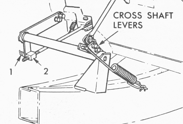
90* is close but its prob a bit more -- like 100*-120*...here is a new 1961 that the British did an analysis of in their famous MIRA document...look at the angles...
Last edited by Frankie the Fink; 02-19-2018 at 04:50 PM.
Even in this photo the inner arm is not pointed down (90 Degree) to ground as shown in the aim. maybe image in aim is not correct. In this image Gorilla spring is not attached so It's hard to tell if this is an "as adjusted" position or one that would change if gorilla spring were attached. On my Z bar the two arms appear to be 90 degrees separation. In this image and aim images it appears, just eyeballing, that they should be more like 160 degrees separation.
Last edited by jerry gollnick; 02-19-2018 at 04:48 PM.
Even in this photo the inner arm is not pointed down (90 Degree) to ground as shown in the aim. maybe image in aim is not correct. In this image Gorilla spring is not attached so It's hard to tell if this is an "as adjusted" position or one that would change if gorilla spring were attached. On my Z bar the two arms appear to be 90 degrees separation. In this image and aim images it appears, just eyeballing, that they should be more like 160 degrees separation.
Mine is as Frankie described above, probably 100-110 degrees . Your rod is about three inches too long.
Mine is as Frankie described above, probably 100-110 degrees . Your rod is about three inches too long.
I will adjust rod length and reposition inner arm to 110 degrees separation and take another photo. should the Gorilla spring be under tension at rest?
OK I adjusted the clutch rod lenght to appear as in the English photo. I'm going to have to stretch the gorilla spring at least an inch to get it to go on in this position. lots of tension. I'm confused as to the function of the gorilla spring. is it a return spring or assist spring. From the geometry it appears more of an assist. which would suggest the center of the attaching arm to the gorilla spring should be roughly in line. Is there a trick to install the Gorilla spring?
by the way the total light of the clutch rod is 9 1/2 inches. don't know if thats correct.
Last edited by jerry gollnick; 02-19-2018 at 05:33 PM.
makes it a lighter pedal for the brake over. Really you do not need to use it if you installed a diaphragm style pressure plate.
Also, ditch the repro rubber grommet on the repro shoulder bolt. Its too sloppy and really not ideal. You will eat them up with in a few presses on the clutch. Better off going with a brass bushing or poly bushing.
Use the method Frankie describes using a crescent wrench
The gorilla spring is a "bistable" device. Its purpose is to smooth out the 'force over distance' curve as the user engages/disengages the clutch. It actually creates a more uniform, even operation of the clutch in both directions. It is NOT a return spring.
Think of bistable as it applies to old fashioned house light switches. The switch is pushed from a certain position in either direction when it then 'flips' to the opposite stable position with minimal force.
As described in the ST-12 manual a crescent wrench placed as shown in red that is used to 'rock' the Z-bar forward will find the 'sweet spot' where the spring almost jumps into place. The ST-12 also has the adjustment procedure but there really isn't that much "adjustability"...
People that remove the spring must not have done well in geometry class...its not a difficult concept..
Last edited by Frankie the Fink; 02-19-2018 at 05:51 PM.
Yep. i played with the adjustment and can find a neutral point and a point where it pulls back or slightly pulls down. interesting geometry. there is also an adjustment on the arm that the spring attaches to. It acts like a fine tuning adjustment. However, all that being said there is no return spring. only a small anti rattle spring. With no return spring how is returned accomplished? When the gorilla spring is adjusted to neutral it is not stable. So my guess is it's adjusted to be slightly pulling back and acting as a return. ST12 is not very helpful here. The second photo shows the spring in a neutral position.
Last edited by jerry gollnick; 02-19-2018 at 06:14 PM.
makes it a lighter pedal for the brake over. Really you do not need to use it if you installed a diaphragm style pressure plate.
Also, ditch the repro rubber grommet on the repro shoulder bolt. Its too sloppy and really not ideal. You will eat them up with in a few presses on the clutch. Better off going with a brass bushing or poly bushing.
Use the method Frankie describes using a crescent wrench
Do you have a supplier or part number for a brass busing?
 02-19-2018, 03:53 PM