When you click on links to various merchants on this site and make a purchase, this can result in this site earning a commission. Affiliate programs and affiliations include, but are not limited to, the eBay Partner Network.
Seeing as I have the motor out of my 67, I am thinking about upgrading the headlight wiring as they are pretty dim.
i have read through darn near all of the threads that cover the subject and have read the articles on MAD enterprises website as well as Daniel Stern's site.
Wondering if anyone has experience with the Headlight Power Upgrade Harness from Ecklers?
I don't know why you would want more than one fuse...
Haven't looked at the kits but if they use the dimmer switch as the 'trigger' for the relays you only need a fuse at the main power feed to the two (hi/lo beam) relays...
Last edited by Frankie the Fink; 02-21-2018 at 07:48 AM.
I can get harness for $50. So I was just wondering if it was better to do that or get the parts from MAD. For some reason I have not been able to get a hold of them.
But after researching.
Looks like I need (2) relays. I need to take 12v from the horn relay to provide power to the new headlight relays. Ground both of the new relays. Make a new connector that will plug into the existing headlight wires, closest to the radiator support. From there I will grab the new "trigger wires" for the relay. And finally run the power out out from each relay to each of the existing extension harnesses for the headlight buckets.
I think that should be it.
Do I need to run a 12v from the BAT on the alternator to the horn relay it just use the horn relays 12v?
I generally just make headlight relay harnesses for the cars I equip with them. Of course, I've got the right tools and supplies (really good crimpers, high quality connectors, etc.) to do the job right.
As for the one fuse/two fuse argument. A single fuse means, if there's a fault that blows the fuse, you lose all your headlights until you replace the fuse. That's not the safest option, although it is basically what was stock in many American cars up through 1997.
Implementing two fuses with two relays, one for low beams and one for high beams means you can switch beams and drive with some lights, maybe, if the fuse blows. I'm not a fan of limping home with high beams only and annoying everyone on the road in the case of an issue.
My preferred method is the one that meets 1998+ safety standards. Separate fuses for the left headlamps and the right headlamps. Implementing that takes a total of 4 relays, but any failure or damage takes out only one side of your headlights, not both. I generally accept the added cost of 2 more relays, and the increased likelihood of a failure from the increased component count. Trading that for one fully functional headlamp when a failure occurs seems to be a good trade off in my opinion.
Last edited by C6_Racer_X; 02-21-2018 at 08:17 AM.
As I see it, the main advantage of a relay system is to provide higher voltage to the lights. That is done by using larger wires running shorter distances to carry the main power to the lights. Power at the horn relay is shared with other systems and is not as direct as a heavy gauge wire direct from the alternator. So, a relay system from the horn relay will be brighter than stock, but maybe not as bright as one directly from the alternator. Will you be able to see the difference? I don't know.
As I see it, the main advantage of a relay system is to provide higher voltage to the lights. That is done by using larger wires running shorter distances to carry the main power to the lights. Power at the horn relay is shared with other systems and is not as direct as a heavy gauge wire direct from the alternator. So, a relay system from the horn relay will be brighter than stock, but maybe not as bright as one directly from the alternator. Will you be able to see the difference? I don't know.
The horn relay is absolutely where you want the main power feed for ANY aftermarket electrical accessory...
The relays are more than that...they take the load off the headlight switch so it just becomes a low-amp 'trigger' for the relays. Original switches are showing their age and the repros are worse and the thermal relay inside the often trips unnecessarily causing headlights to 'strobe' as if there was an overcurrent condition. Relays eliminate all of this.
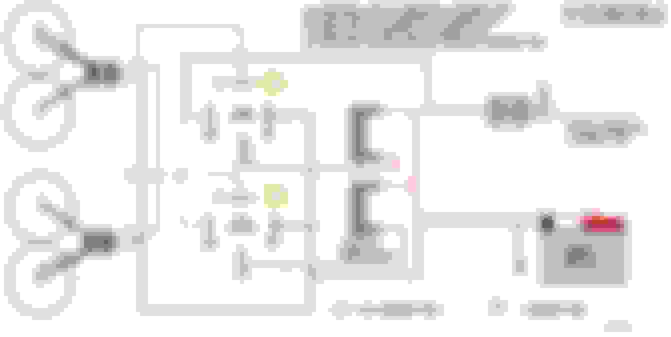
There are several circuit diagrams available and I can provide one if needed.
The horn relay is absolutely where you want the main power feed for ANY aftermarket electrical accessory...
I've heard that from a lot of C2 and C3 guys. I haven't had one in my shop in so long, I'm not sure I'd agree with going there for power to a headlight relay harness.
It would take a large (AWG 8 or 10), short (12 inches, maybe 16 inches, but preferrably shorter) unfused wire from the horn relay post to the alternator or battery to convince me.
My preference is to go to the "bat" post on the alternator, or directly to the battery. Whichever is closer to the headlights. On my S10 pickup, I went to the positive battery post because the battery lives behind one of the headlights. On the Mercedes (W126, 560SEL), I went to the alternator post because the battery is back in the cowl area, below the windshield.
The way the C2 voltage sensing works, if you take major accessory power leads straight off the battery you guarantee your voltage regulator's remote sensing method of providing charge will work incorrectly and the dashboard BATTERY gauge will read strangely.
Details are on the Mad Electric tech portion of their web site and I've gone through the whole drill with my 63's aftermarket air conditioning install...as have others
I will see if I can get ahold of MAD to order the kit. If I cannot get a hold of them, I will source my own 85 86 87 30 relays and wire it myself. Looks like I will need to gather up (2) delphi 56 connectors and some ends as well as a crimper.
The way the C2 voltage sensing works, if you take major accessory power leads straight off the battery you guarantee your voltage regulator's remote sensing method of providing charge will work incorrectly and the dashboard BATTERY gauge will read strangely.
Details are on the Mad Electric tech portion of their web site and I've gone through the whole drill with my 63's aftermarket air conditioning install...as have others
OK. So these have the external voltage regulator. That's different from the applications I've usually done.
I understand the need to have the voltage regulator sense wire on the same terminal that serves as power distribution point. Is that wire normally attached to the horn relay post on the C2/C3? Or do You add that MAD CN-1 part and attach everything to that?
Originally Posted by johngandersonjr
I appreciate all the responses.
I will see if I can get ahold of MAD to order the kit. If I cannot get a hold of them, I will source my own 85 86 87 30 relays and wire it myself. Looks like I will need to gather up (2) delphi 56 connectors and some ends as well as a crimper.
For relays, I generally use the skirted, "Weatherproof" relays and sockets. http://amzn.com/B003TEO9GU is a Hella weatherproof relay with mounting tab.
For the sockets, I use something like http://amzn.com/B000VU9D0C, but I generally pull out the wires and crimp terminals on my own wires to avoid any splices. You can get "kits" of cheaper (Chinese) relays with sockets.
For the headlight connection, http://amzn.com/B01N533URZ and I throw out the wires and crimp my own female spade connectors on my own wires and push them in. Again, I like to avoid splices or butt connectors. I don't have a link for the spade lugs, I keep several styles here, and I always have a match for what I find in those headlight connectors (although headlight connectors ordered at different times seem to come with different styles of female spade connectors).
This is exactly what I was looking for. I had started to draw it up on my computer, but this saves me a lot of time.
Could you tell me where you sourced the box as well as what gauge wire you used?
Originally Posted by buns
johngandersonjr, I built a headlight relay kit for my '66 recently. I was able to source the Packard 56 connectors, so there is no need to hack into the original harness.
I used 14 gauge for the black and red wires, 16 gauge for the brown and green. It's such a short run, I didn't feel the need to go larger. This chart shows what gauge you need.
 02-20-2018, 06:51 PM