When you click on links to various merchants on this site and make a purchase, this can result in this site earning a commission. Affiliate programs and affiliations include, but are not limited to, the eBay Partner Network.
"Full" conversion of voltage regulator to solid state
I got talked into doing another one of these for a pal that is heading for judging quite soon (his original crapped the bed last week)...The goal is to invisibly convert an old mechanical, “vibrating points” Delco Remy 12V DC voltage regulator to a solid state equivalent. Pictured is a lightly used Wells VR-715 solid state regulator and a used (dead), but original, "512", "2J"-dated,1963 regulator. The cost was $20 for the Wells and $50 for the original V/R.
Most conversion are done by just putting the original top Delco-Remy case on the VR-715’s solid state unit’s base. This is easily detectable under some light scrutiny. So an invisible conversion will require housing the VR-715’s circuit board completely inside the Delco-Remy case (both top and dated and numbered base section)…
Here is what I'm working with:
Last edited by Frankie the Fink; 02-01-2020 at 08:36 AM.
You may want to check out your insulation job with an ohmmeter ensuring the external spade connectors are connected to the circuit board and that the brass screws do not short to the metal base.
If that is good you can mount the V/R to the car with the original harness and original ground and the radio suppression capacitor if one exists. At a fast idle a multimeter reading across the battery should be between 13.8V and 14.2V….as shown in the test of this converted unit attached to my car.
This setup can handle up to 135 amps if your alternator has been upgraded for accessories.
When mounted and operating the new V/R is undetectable from an original…even for NCRS judging. Judges can’t peer far enough to the back of the converted unit to see any differences and with the Delco-Remy lid and dated and numbered base it appears as factory.
The gauge on the dash will not show "snappy" or overly quick fluctuations of the needle as seems to be the myth. My conversion passed regional judging including ops checks. I’ve never done a PV but there is absolutely no reason why this conversion wouldn't pass that testing also.
Converted unit temporarily installed on my split window for testing.
The first step is to remove the covers on both units which require taking the screws out of the original Delco-Remy unit and drilling out the rivets holding the VR-715 top case onto the base…
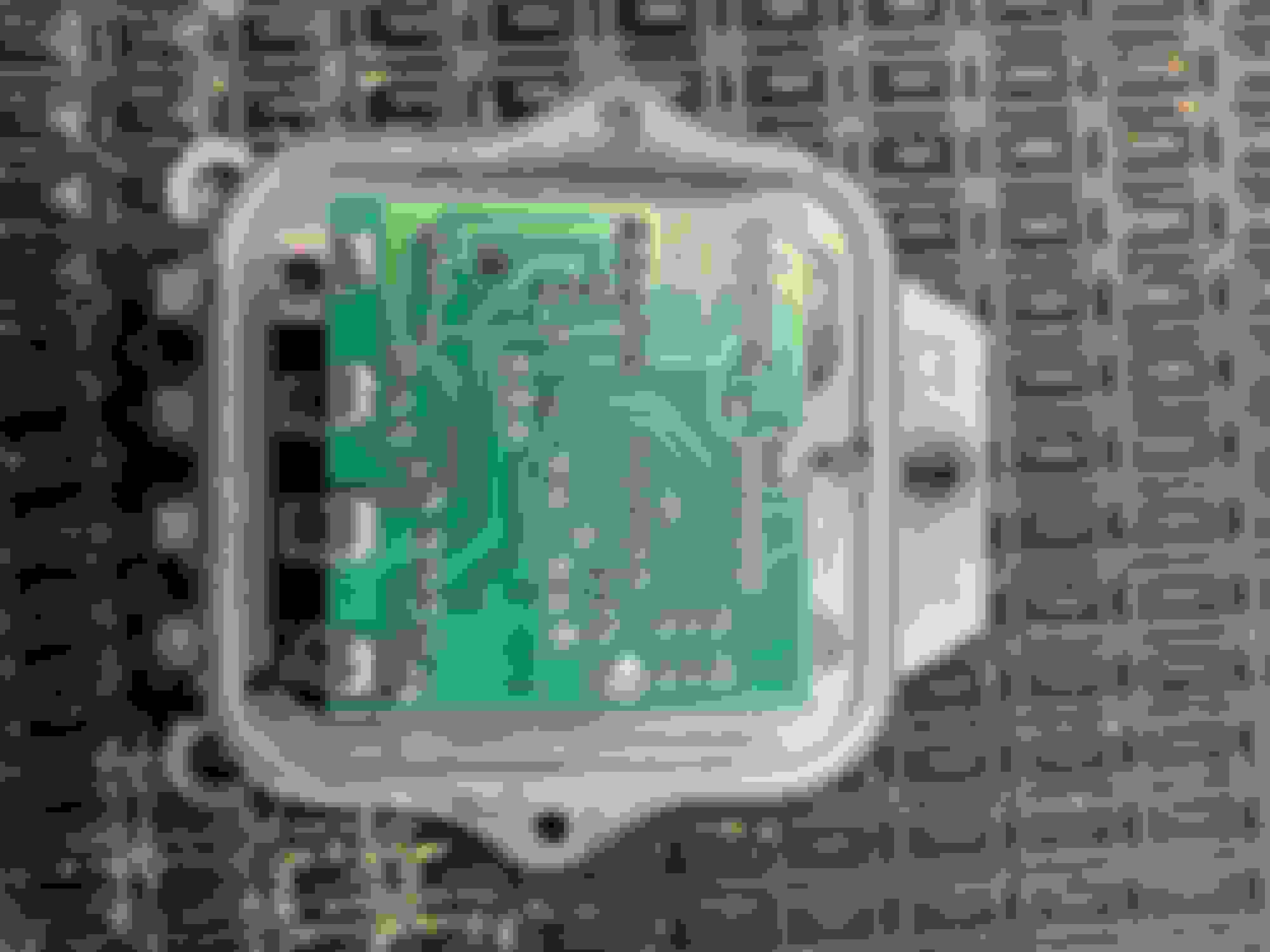
With the covers removed its time to remove the circuit board from the VR-715 SS regulator; using an appropriate sized drill bit, drill out the 5 rivets holding the solid state circuit board.
Next, and the worst part of the conversion, is “prepping” the base of the original Delco-Remy unit. The goal is to convert this base to support the solid state circuit board while preserving the back face where possible to make it appear original. To wit, try to keep the two wire round approx. 1” long resistors on the rear.
So, the prep requires first snipping all of the small leads off the base rivets.
Then the adjustment arm must be removed by cutting it off the post and removing the plastic adjustment thumb screw.
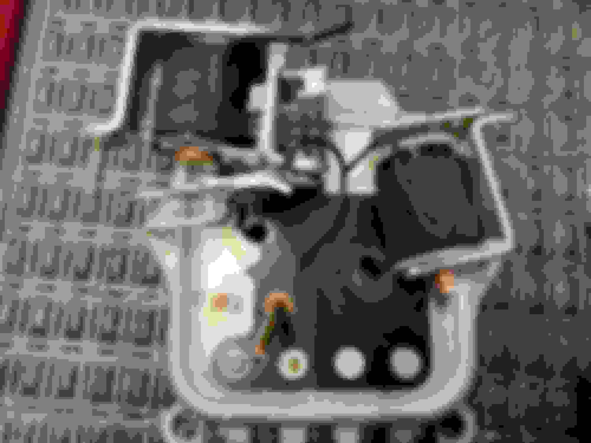
Next remove the two armatures by drilling out the copper rivets from the rear of the base…be patient, drill a little with an appropriately sized drill bit then lever the base of the armatures from the other side with a screwdriver to see when they’ll come loose.
After that’s done then the copper stud must be removed by the same process. It’s OK if the plastic insulator is nicked in a few places as going to be removed anyway. At this point the base should be clear of the old electrical components…
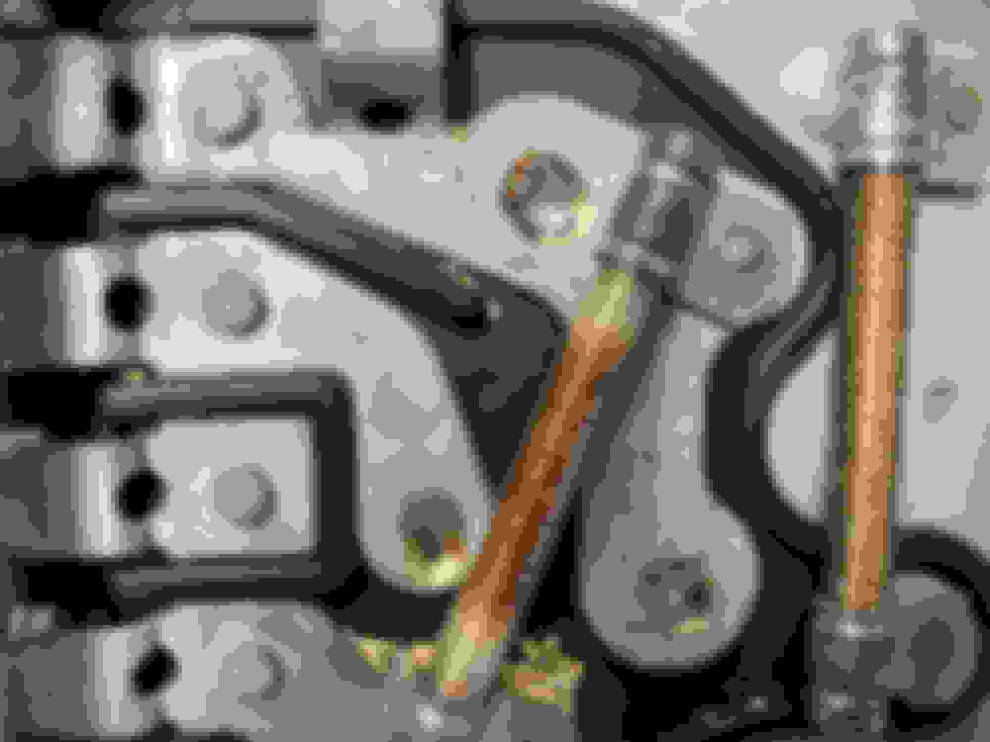
Now drill out (or grind off with a Dremel) the rivets holding the four original electrical spade terminals….mark the hole with a Sharpee (as shown) for the 5th hole needed in the base for the upper circuit board terminal. A new screw will go there.
Remove any remnants of the black plastic insulator on the inside of the base and you should have a bare, original base with 5 holes drilled in it and the separate original terminals loose and separate (I “break” the one wire round resistor as shown on the rear– unlike the other one it may affect the operation of the circuit board).
Original base is now prepped for the solid state circuit board install.
NOTE: VR-715 solid state circuit boards may differ in size, appearance and components, but the conversion process is the same...
Last edited by Frankie the Fink; 02-01-2020 at 08:14 AM.
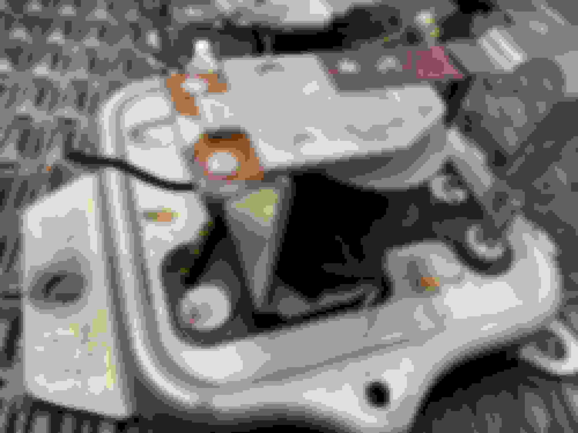
Now insulation of the circuit board and spade terminals is critical – I used a piece of an orange kitchen plastic, thin cutting board to insulate the circuit board connectors from the internal base’s metal (as shown - do NOT insulate under the top screw!). Brass #4-40 hardware (screws – as short as possible, washers, lock washers and nuts -- all from Ace Hardware) is used to make the electrical connections in place of the original rivets. Before you put the screws in decide now if your plastic electrical connector retainer strap is too old and brittle to keep on the converted unit (yellow rectangle in picture below), if so, then migrate the one off the solid state unit to the converted unit (this make take some trimming and creativity).
I used carefully selected, properly sized shrink wrap around the screw threads to isolate the metal base from the circuit board terminals (as shown). It’s a bit of a struggle to get the insulated screw through the original spade connector, original metal base, the plastic insulator and the new circuit board terminal but it ensures a solid, insulated electrical connection.
Note that the direction of the screw is reversed in the top 5th screw hole in the picture above to allow the original, Delco-Remy cover to seat completely onto the converted base.
Last edited by Frankie the Fink; 02-01-2020 at 08:22 AM.
You may want to check out your insulation job with an ohmmeter ensuring the external spade connectors are connected to the circuit board and that the brass screws do not short to the metal base.
If that is good you can mount the V/R to the car with the original harness and original ground and the radio suppression capacitor if one exists. At a fast idle a multimeter reading across the battery should be between 13.8V and 14.2V….as shown in the test of this converted unit attached to my car.
This setup can handle up to 135 amps if your alternator has been upgraded for accessories.
When mounted and operating the new V/R is undetectable from an original…even for NCRS judging. Judges can’t peer far enough to the back of the converted unit to see any differences and with the Delco-Remy lid and dated and numbered base it appears as factory.
The gauge on the dash will not show "snappy" or overly quick fluctuations of the needle as seems to be the myth. My conversion passed regional judging including ops checks. I’ve never done a PV but there is absolutely no reason why this conversion wouldn't pass that testing also.
Converted unit temporarily installed on my split window for testing.
Converted units output at about 1000 RPM.
Last edited by Frankie the Fink; 01-31-2020 at 04:41 PM.
Ha! Hardly - but with the paucity of original, working mechanical V/Rs for certain cars, and the latest non-adjustable repros, I think this will be a common mod (sorta like those modern AGM batteries hidden inside OEM-appearing Delco tar-top cases) and its a "once and done" conversion. I've been running mine for 5 years now with Vintage Air A/C and an original alternator upgraded to produce 100 amps full out...and haven't touched it (or even thought about it) in all that time.
For $70 and a couple of hours of my time this gent has a factory appearing V/R he'll prob never have to mess with again...
In the unlikely event this V/R should fail; its a 40 minute job to replace the circuit board with a new VR-715 unit since everything is now held together with screws...
Maybe Dave Zuberer will pull all of this into a single PDF to make it less unwieldy...
Last edited by Frankie the Fink; 02-01-2020 at 09:08 AM.
Very nice Frank. You've got a real knack for explaining things!
Pretty interesting, I did something like it back around '92. I think it was before aftermarket had the solid state units. I took the regulator from an internal reg GM alternator and put it in a gutted unit. Not plug and play as your conversion is however. I had to rewire the brushes and add the triple diode from the internal alt. Worked pretty good.
Very nice Frank. You've got a real knack for explaining things!
Thanks - it cones from many tedious hours of meetings and presentations about very technical topics to non-techie customers and clients...
Pretty interesting, I did something like it back around '92. I think it was before aftermarket had the solid state units. I took the regulator from an internal reg GM alternator and put it in a gutted unit. Not plug and play as your conversion is however. I had to rewire the brushes and add the triple diode from the internal alt. Worked pretty good.
Pretty clever considering what you had available to work with at the time!
Last edited by Frankie the Fink; 02-01-2020 at 05:17 PM.
With Frank's approval, here is the PDF version of the VR conversion thread.
Thanks Frankie!
Dave Z
P.S. I have fixed the lower figure on pg 6. The circled area for drilling was improperly located. Please download the corrected file attached. Thanks. Dave Z
Last edited by DZVette; 02-02-2020 at 10:32 AM.
Reason: Correction on pg 6 bottom figure - screw hole location
Thanks, this is amazing. Thanks so much for documenting it so nicely.
I just noticed the other day that my original voltage regulator (restored by John Pirkle around 2005) is now charging the battery at 15+ volts, which I think may be a bit hard on the AGM battery from Restoration Battery. I have added this voltage regulator conversion to my "to-do" list.
Nice sharp drill bits and securing the base somehow to enable drilling out the rivets is key...after that its a walk in the park!
An assortment of shrinkable tubing is needed for the screw insulation, Harbor Freight has those assortments in plastic boxes for cheap.
I noticed the circuit board you used (Wells) looked older, with discrete components rather than the surface mounted chips on the newer ones I've seen. The one you used would seem more robust. Are these still made that way?
Greetings all. Please see post #12 for a corrected version of the PDF. Download the corrected version there.
In particular, check the bottom figure on page 6 for a relocation of the circled area for drilling.
Happy Super Bowl watching!
Thanks.
Dave Z
I noticed the circuit board you used (Wells) looked older, with discrete components rather than the surface mounted chips on the newer ones I've seen. The one you used would seem more robust. Are these still made that way?
Dan
The one in this thread is indeed an older VR-715 that I just happened to have around....
On my car, I used a newer VR-715 as pictured below and yes, you can see some differences:
I doubt it matters much as any of the solid state versions are ultra-reliable...
As I've said earlier the one pictured here has been going strong for 5 years now.
Last edited by Frankie the Fink; 02-02-2020 at 03:35 PM.
Greetings all. Please see post #12 for a corrected version of the PDF. Download the corrected version there.
In particular, check the bottom figure on page 6 for a relocation of the circled area for drilling.
Happy Super Bowl watching!
Thanks.
Dave Z
Thanks Dave - I should have caught the minor glitch on my initial review, what can I say ?
 01-31-2020, 03:36 PM