When you click on links to various merchants on this site and make a purchase, this can result in this site earning a commission. Affiliate programs and affiliations include, but are not limited to, the eBay Partner Network.
Moving forward!
I removed the flywheel locating pin, went to my buddy's shop and we dialed the pressure plate right in the center, drilled the 3 hole that were too small (BBC pressure plate with metric bolts) and drilled the pressure plate for the new location of the locating pin (sorry forget to take pic of the PP installed.
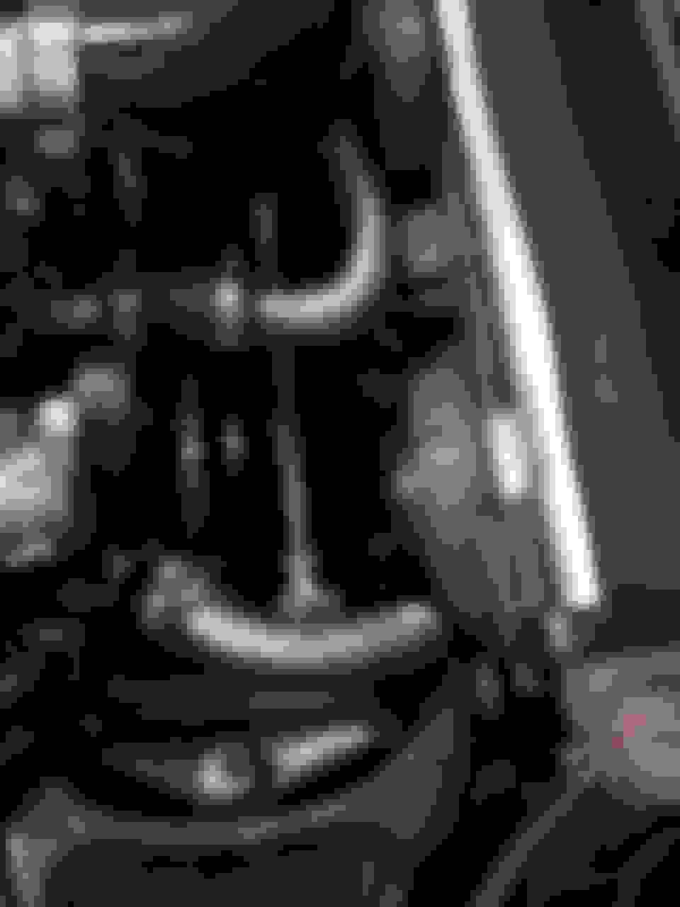
I made a bracket for the slave cylinder.
All seems fine, except that the slave cylinder has a spring in it, that makes it push all the time. So whatever position I set the adjustable fork pivot, it's always there to provide enough push for the throwout bearing to ride the pressure place.
Throw out bearing are not supposed to ride the PP all the time, aren't they?
Maybe the spring in the master cylinder, that actual act as a return spring will conteract this always pushing slave, once the circuit is devoid of air?
Tomorrow I got pick a clutch custom line as well as a -6AN adapter for the steering pump. I'm gonna test my theory.
Throw out bearing are not supposed to ride the PP all the time, aren't they?
When my machinist buddy pinned my pressure plate to the flywheel- instead of stamping them "A.B.C" or "1,2,3" to make sure I could relocate it correctly- he decided "ATM" was more appropriate !!!
Ok, here's some updates, I'm moving ahead at good speed.
While I had the transmission out I though it would be a good time to take more picture of my Chevy WC trans mount.
Here you can see it's made form the original trans mount (it was for a TH350, not sure manual one are the same).
Here's how it fit with the other bracket, note how offset the holes are.
And that's the rear view of the bracket.
Then it was time for insertion. Boy that was a tense time, especially without helping hand.
You'll not there how optimistic I was, with the exhaust manifold still on. I had to remove then eventually, but, hey at least I tried.
I expected the batwing oil pan to give me headaches, turned out pretty good.
All went well until I realize I had the wrong body mount. The one that reuse one of the LS body mount hole as the bottom SBC mount.
So My engine had to stay up in the air for a week until I get those.
They put the engine 1" back, putting it in the orignal SBC position, back-of-the-engine-wise.
Annnnd now it's in. phew.
I was time then to focus on the clutch master cylinder.
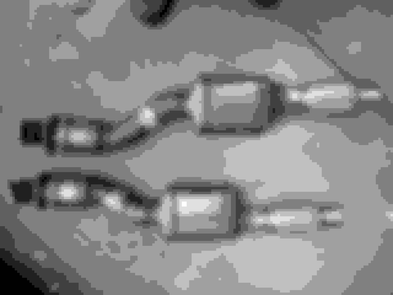
I made this adaptor, shamelessly inspired by post on the forum.
Turned out this was just the lenth I needed to not have to tweak the length of the push rod. Except for the hole diameter, some fill welding, a good grind and some drilling and now we have the correct hole size.
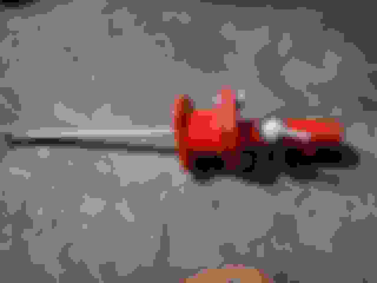
Here's the slave installed
And the master.
And the reservoir sits nicely on top of the hydroboost.
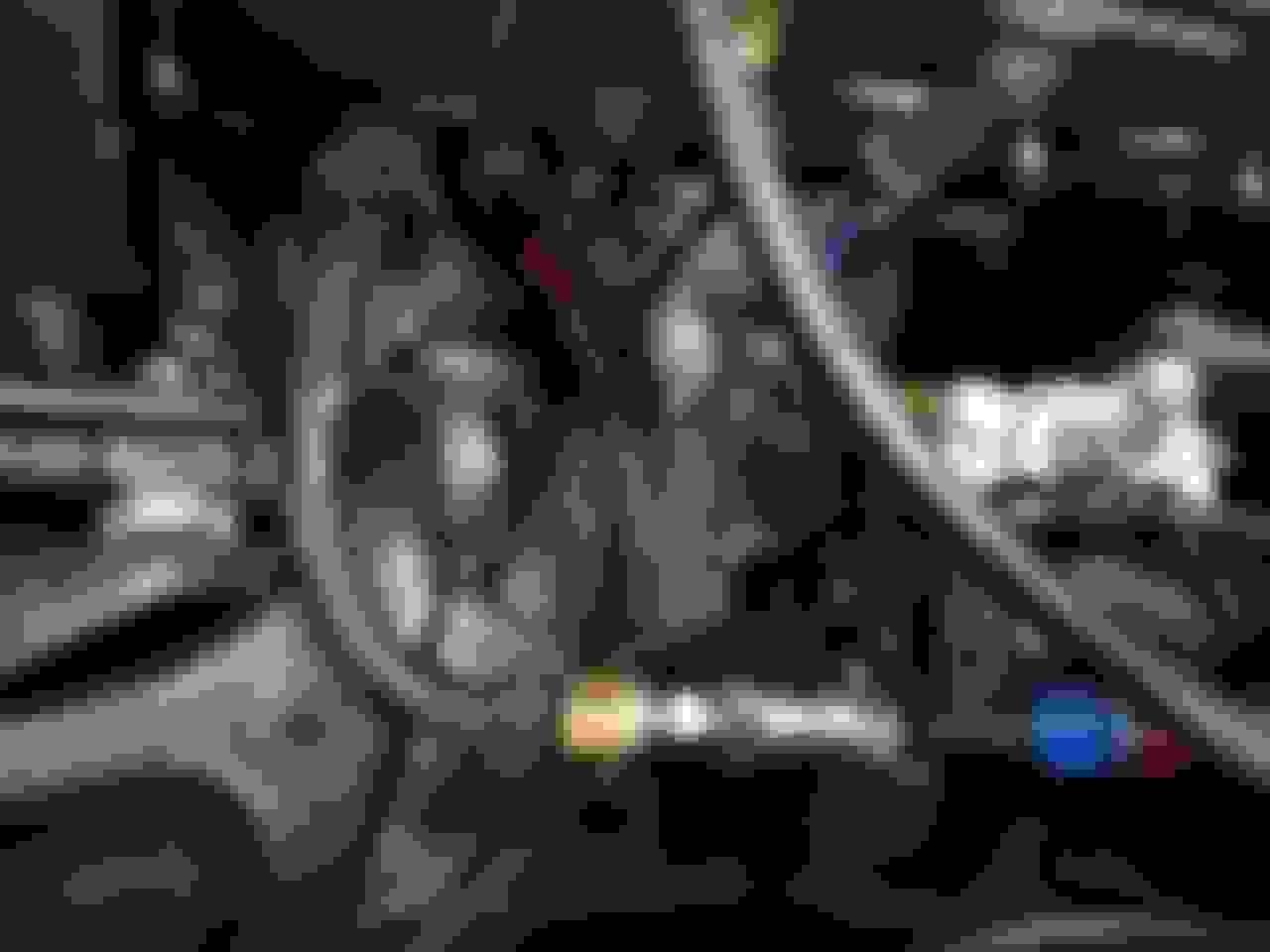
Also done routing the power steering pump.
The line is against the head, I'm considering putting a fiberglass sleeve of the time.
Yeah, the return side is quiet a collection of different fittings. I'll probably order a female -AN6 to nipple fitting to replace this.
Now I hit a major bump, the scrapyard fan just don't fit. they hit the control arm axes in not way I can cut them to fit. That's a bummer. I'm gonna have to find something else. Advises welcome.
Thanks for watching.
An AN barb would be the ticket!!!
Major bump? Really? After all you've done? I'm thinking it's not really even a speed bump!!!
That what I meant with "-6AN female to nipple fitting", but you're right, it's barb, not nipple.
ordering right now.
Originally Posted by Richard454
Major bump? Really? After all you've done? I'm thinking it's not really even a speed bump!!!
You're right, not a bump, because everything is a bump, just only tonight I fought tears and sweat to get the driver side exhaust manifold, had to remove the plugs, the clutch slave cylinder and the U shaped plate that holds the steering column to the firewall. And afterward I had to make a cutoff from this plate to not interfere with the exhaust heat shield.
It's just I thought I had this section squared up. Next weekend I go to the scrapyard get a Taurus fan, as I know several people used them on Vettes.
Originally Posted by Richard454
Nice work...
Carry on!!!
I will, I will.
Originally Posted by doorgunner
Take a break and think about the fan(s) fitment ...�...you will solve the problem!
I swear I tried everything. Even if the dimension are correct the fan extend way too far and their shroud is way to high, and that's the shroud that holds the motor.
Big thanks to both of you for the advice and the kind word.
Just trying to be politically correct...I don't think as a male I can say nipple and female in the same sentence...as it might offend somebody!!!!
Given the M/F ratio over there we're pretty safe.
Originally Posted by Richard454
BTW- I have two sets of sparkplug wires- brand new take offs.. Shoot me an email richard454 at comcast dot net if you want them.
Wow, that's kind of you. While I already have a set I have to admit it's an ugly mix of junkyard picks. So given I'm not taking it off hands of more needy than me, I'll gladly take a set. email on the way. Big thanks.
Wow, that's kind of you. While I already have a set I have to admit it's an ugly mix of junkyard picks. So given I'm not taking it off hands of more needy than me, I'll gladly take a set. email on the way. Big thanks.
You are welcome...They were just sitting around and I'm not gonna use them...Now get back to work!!!
Look who's mate on replying to thread followers. My apologies, I was stuck on a build detail, and when I do, I procrastinate, on everything.
I encountered another bump on the cooling side, the straight water neck just too close to my spreader bar.
So I ordered a 45� swivel one, and we now have the cooling sorted. Still have to make the fan mounting tab a bit more sturdy, and little paint wouldn't hurt.
The fan frame is from a Ford Focus but I swapped out the motor for those of the Sebring.
Now the fuel.
First I decided to put the fuel rail back into it's original orientation, cut the support tab on the inlet port in otder to bend it enough to clear the coils. The unconnected AN line on the passenger side is the return line (now obsolete).
Then the intake. It's a temporary setup as the air filter lie just under the hood vents (not to be driven in the rain).
I said temporary because I have plan for the future.....
While I was at it I took some time to rework the engine bay harness. I had this junction box I picked in a GM truck at the scrapyard. It helped the sort out all the 12v wires.
And now the bug : The ECU location.
Where was I going to put this brick?
With the help of the example of some fellow CF member, I came up with this:
It the frame of the ECU support you find in GM trucks.
I trimmed it down to what you see:
It straps to the coolant overflow tank.
The connector is stuck all the way back into the fender, but it's ok because the retainer mechanism still work on the support. So I can unclip it, pull it out and then disconnect it.
Stilll have the fusebox to locate, much easier job.
Took one more bit off the monster's butt.
Made this weird piece:
So I can tuck the fusebox right beside the ECU.
No planning in that, just some dumb luck. Most of the wires on the top go back into the ecu, I'm out of wrapping tube for now. Bottom one goes directly to my fancy red box.
I'm really glad I decided to start using this Mig welder I bought myself for last Xmass. Before I would rely on other people to get my stuff welded, now for non critical part I consider doing them by myself, and that opens a lot of new horizons.
I'm really glad I decided to start using this Mig welder I bought myself for last Xmass. Before I would rely on other people to get my stuff welded, now for non critical part I consider doing them by myself, and that opens a lot of new horizons.

 08-23-2018, 08:20 PM