When you click on links to various merchants on this site and make a purchase, this can result in this site earning a commission. Affiliate programs and affiliations include, but are not limited to, the eBay Partner Network.
Yeah another looooong post with tooooo many pictures
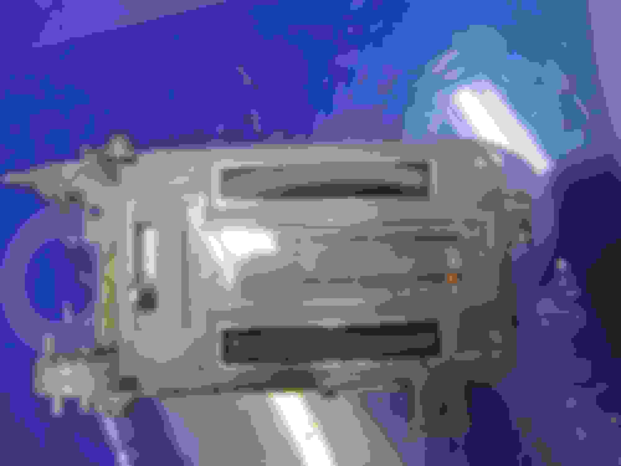
The original lens was pretty scratched up and I’d already polished it once years ago so I figured while I’m in limbo for a few days I’d might as well open it up and give it the once over.
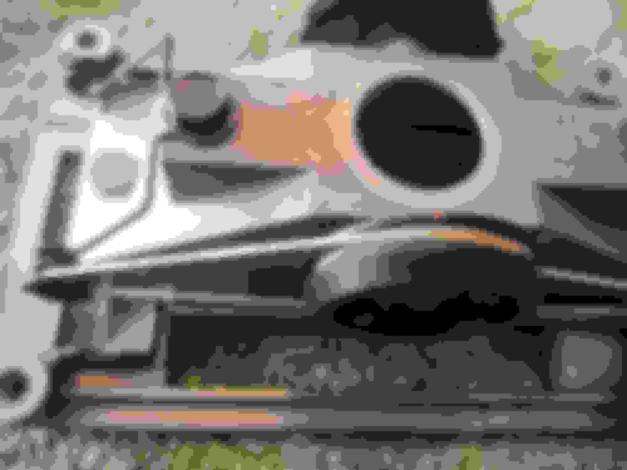
Tore everything apart, the lens is the farthest thing in there so might as well take it all apart
The metal is bent over to hold the lens and backing plates in place, there should be a little bit of a tab (one at the bottom and one at either end of the “T”) but looks like mine were pretty rough from last time (was that really that many years ago…) Use a pair of needle nose pliers to gently straighten out the bent areas and release the pieces.
Diagonal (side) cutters or two small flat screw drivers are handy for removing the spring clips on the outsides of the two thumb wheels. Do not lose the spring washers
Clean and degrease everything, tooth brushes work great. I did a little painting and general tidy work. Added reflective silver paint to the inside of the light cup in hopes of making it slightly brighter (will also be installing LEDs so …)
Gather all the parts back up and make sure I still have most of them
There are three different screws used for the main assembly,
4 large long screws and 4 thinner screws of the same length
10 short screws
4 larger pointed screws
Here’s the comparison of the smaller screws. You can see the ones with the slightly thinner thread
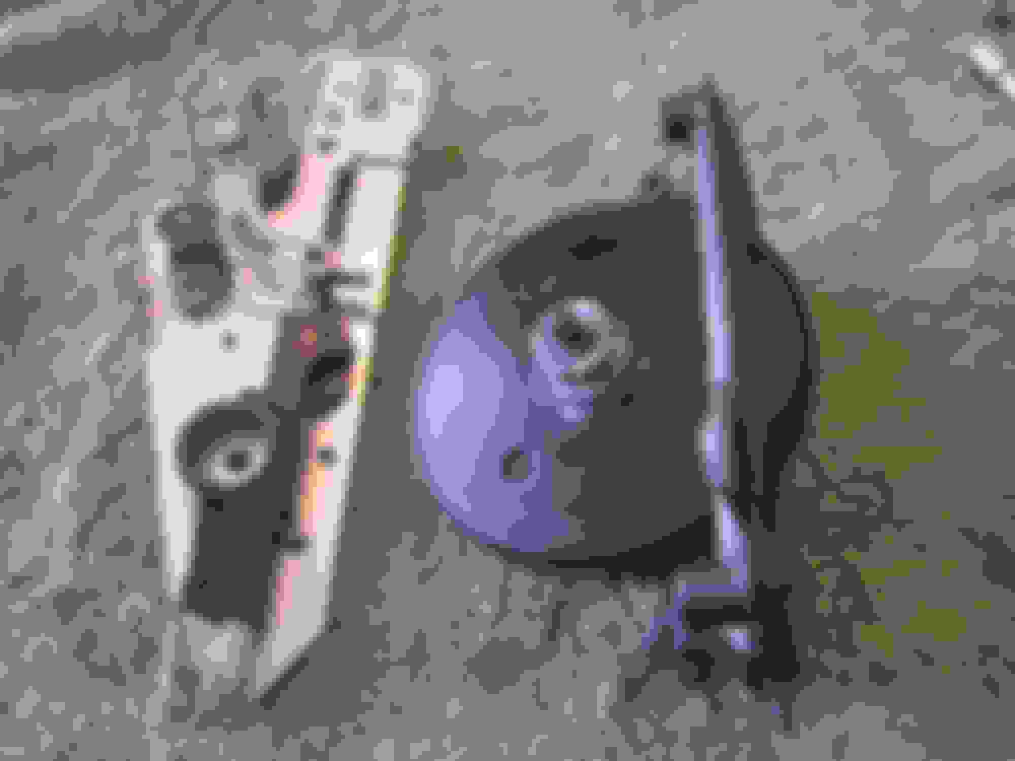
I didn't take the drive wheels off the light pot since the retainer looked like something I don’t have any way of replacing if it broke, and it looks like something that will easily break
The first piece that goes in is the U-channel shaped reflector, it will really only fit on way but just make sure the larger bent tap is towards the top of the “T” in the light pot. It may need a little push to fully seat but it will sit all the way down into the pocket.
The plastic indicators were in good shape so I cleaned them a little and didn't bother with any additional painting or anything. They attach to the string by having it wind around the three little tabs here. The string came off easily but these look pretty fragile.
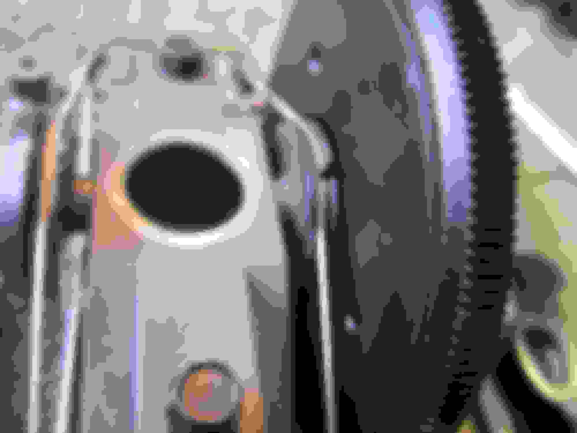
They just slide along the side of the light pot so make sure that lip is smooth and free of any nicks/paint/etc.
The flat metal plate goes on next.
Looking at the flat plate I notice there are 6 little tiny nibs sticking up, the old lens actually had some tiny dimples in it, the new one doesn’t.
Either the dimples were caused by being pressed against this plate or were in the lens but they did locate the lens and plate together. I installed the new lens hoping those nibs will stick in a little and lock to two together.
The main cover can go on now. I stripped mine and gave it a fresh coat of paint (JD blitz black in this case) and carefully cleaned off the chrome lips using a cloth and lacquer thinner
Here’s where those tabs need to be staked back in to hold everything. As I said, mine were in pretty poor shape so I just used an automatic center punch and folded the edges left beside where the tabs were to lock everything firmly in place. Make sure it’s tight but don’t over do it.
I installed the 4 plastic wheels on the tension bars and then used 2 short screws to bolt them to the center light pot.
The string need to have the part where they are tied into the loops passed into the drive wheels and then tuck the knot into the recessed area, this will let the thumb wheels sit flat.
If you don’t tuck these in, they could get under the edge of the wheel and make it sit on an angle, just enough to make it look bad as you rotate them. (trust me on this one)
Loop the string once around the wheel and then out to each of the tension pulleys. I put it around each tensioner and then passed the loop over the center wheel, worked easier than trying to get the last loop over the little pulley while pressing the tensioner in etc etc etc.
Then move the wheel so the know is facing the indicator (which puts it approximately in the middle of its total travel) and slide the indicator to the middle and using a set of tweezers wind the string around the clips on the indicator. This can be fine tuned later
The sliding bars are unique left and right, and I've seen they are different on the AC cars. There is a series of notches cut on the one edge of each bar
On each side plate there are these little hair-pin springs.
These install (short bolt) through the larger loop (doesn't seem to work the other way) and the smaller loop sticks through the slot in the plates.
As the control bars slide in and out, those hair pins will fall into the notches and that’s the detents you feel which should indicate what position the controls are in.
In this case the 4 notches are the 4 positions on the left of my non-AC car (off, air, mix, defrost) on the right side there are only two, full cold and full hot
Smear some white grease into the plastic control rod guides and install the rods (gear rack towards the center hole in the plastic guides.
Remember which side matters so double check. Use the thinner long screws to attach these to the side plates. If your like me, you're working on these upside down so.....
Now is a good time as any to attach the vacuum valves. These use the 4 longer screw, make sure you install the ground clip at this time.
Now is the tricky part (not really) Slide the control rod all the way back, and turn the indicator wheel so the indicator is all the way to the front (towards the top of the “T”)
Place the thumb wheel into the slot in the face plate and turn it so it engages the two pins in the string wheel.
Carefully bring the side plate and the control together while engaging the gear on the thumbwheel with the teeth on the control rod. You may need to wiggle it a little to align the teeth but not very much
Attach the side plate to the face plate with two short screws.
Check the movement of the thumbwheel / control rod (detents) and indicator.
You can bring the indicator all the way forward or backwards and fine tune the location by sliding it along the string a little using a small screw driver or something. Careful that you don't accidentally knock the string off the tension pulleys
Wipe a little white grease on the side plate and re-install the spring washer and retaining washer, do not over tighten but make sure it’s securely on the thumbwheel shaft
Install the cross brace using two long screws
Make sure the switch is clean and working properly, not a bad time to give it a quick polish since it’s out.
Adjust the control rods to allow the switch to be slid into place and install with 2 of the pointed screws
The two remaining pointed screws are to hole the vacuum plugs on once the unit is re-installed.
There are 2 remaining clips to hold the control cables onto the control rods
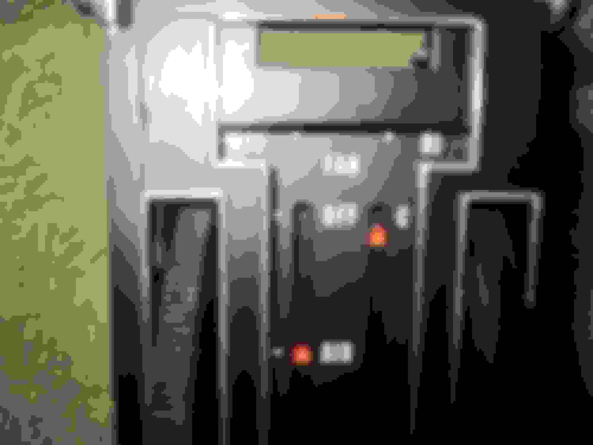
Completed unit
Yet another small job made too complicated. Hopefully the reference images will help someone at some point
M
Last edited by Mooser; 12-01-2017 at 09:20 PM.
Reason: fix photobucket mess
Nice job Mooser!, thanks for all the details.
Using this write up makes this is a made easier future project .
This is the type of write up that makes this forum a great place to do research.
Thanks again,
Derrick
Your write-up on the panel rebuilding is very well done, extremely detailed, and highly informative. I've often wondered what it'd take to re-do my panel: now I know, as do others.
Great write up...thanks. Did you reuse the string or replace it?
The only thing I replaced was the lens, mine was just too far gone to bother with.
The string seems to be some type of woven nylon or something along those lines. I pulled on it somewhat and it's solid so I soaked it in some cleaner and it took away a lot of the black marks.
I don't think it could really get weak or rot (like cotton)
If you had to replace it, some of the braided fishing lines would probably work, zero stretch and all. The ends are tied but there is actually a tiny metal piece crimped around the knot.
A drop of crazy glue would likely work
M
Last edited by Mooser; 12-01-2017 at 09:23 PM.
Reason: fix photobucket mess
I didn't notice whether you just cleaned existing faceplate up or if you repainted it. For the sake of general discussion on these kinds of interior component projects, I highly recommend using a chemical stripper to remove ALL old paint, then repaint with satin or semi-flat black paint (John Deere 'Blitz' black is my preference) for factory-new appearance.
I didn't notice whether you just cleaned existing faceplate up or if you repainted it. ...
I stripped the original plate, lightly sanded the chrome areas and re-sprayed.
For the interior dash parts I've been using the blitz-black, sprays nice, lays down well and has a good sheen (can't get that semi-flat industrial krylon around here it seems)
I do find that letting it sit for at least 2 days before handling and cleaning the chrome edges seems to help, 24 hrs just doesn't seem fully cured or something.
M
Cure was a poor choice of words. What I was trying to get at was wait a couple of days to wipe the paint off the chrome edges, but don't wait too long or you either have to use a really wet rag or rub a lot harder.
M
Ahhh... I always do that within a 1/2 hour of painting, then use a sharp X-Acto knife to shave off the soft paint. Lots easier (and less messy) then trying to dissolve cured paint later, IMO. When shaving off the soft paint, don't try to remove the loose shavings. You could try to blow them off....but don't wipe them off, as it will mar the paint underneath. If you just leave them and let the paint cure a bit (2-3 hours), you can easily brush them off with a soft, clean brush (artist's paint brush, etc).
When painting recessed lettering (center hub caps on ralley wheels), the use of lacquer thinner to wipe the surface clean after painting is a very useful technique.
Either method will work on the heater control and gauge cluster parts. It's up to the owner's preference as to work works best for him/her.
Question Mooser.....I have gotten after my assembly and upon dis-assembly have found that all my Bowden cables were either not anchored ( vent cables ) and the heat/temperature cable was broken.
I know the two vent cable housings are secured to the console ( underneath) but where do you secure the cable housing for the heat/temp cable? Do you have a picture of that to help me?
I have looked in the AIM but the pics are vague. I am stumped. Maybe I am missing a part?
Thanks in advance for any assistance with this.
Fred
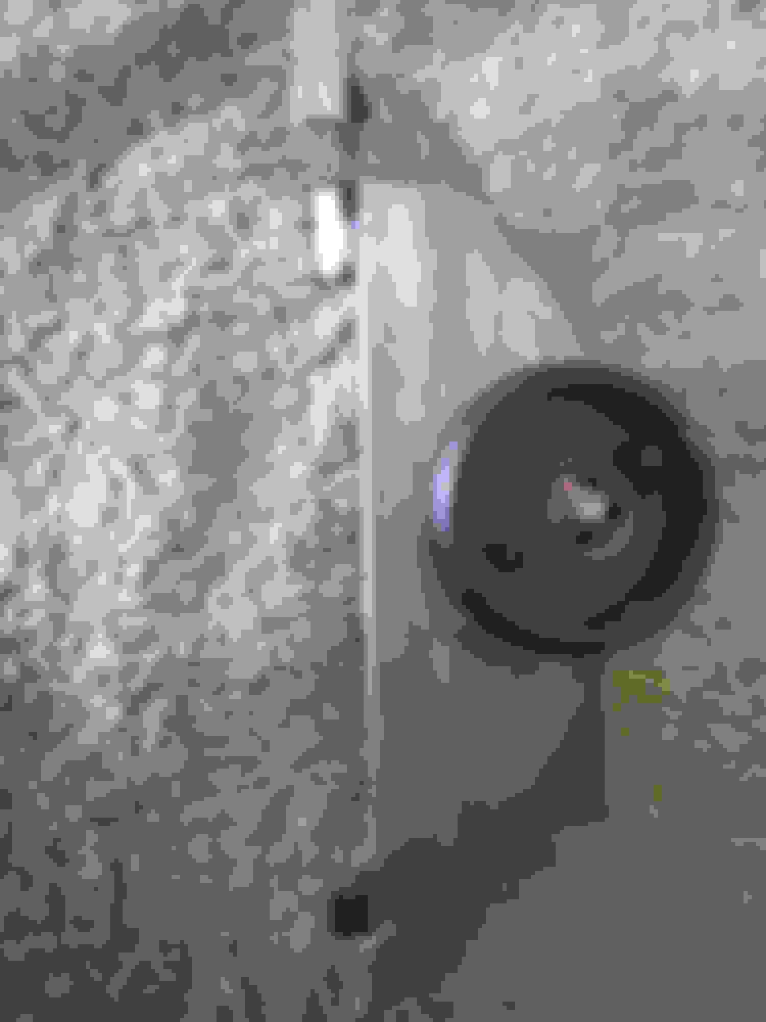
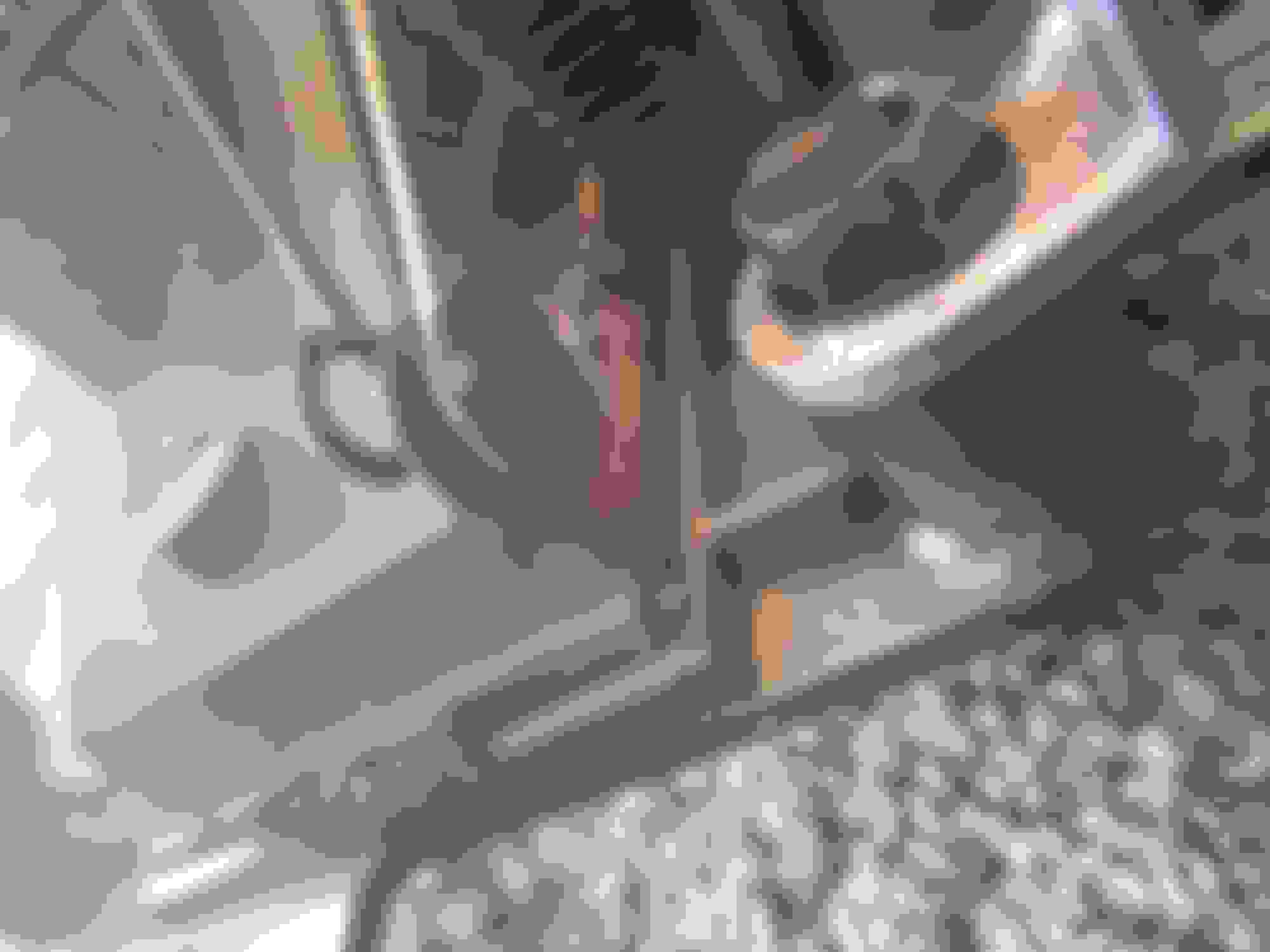
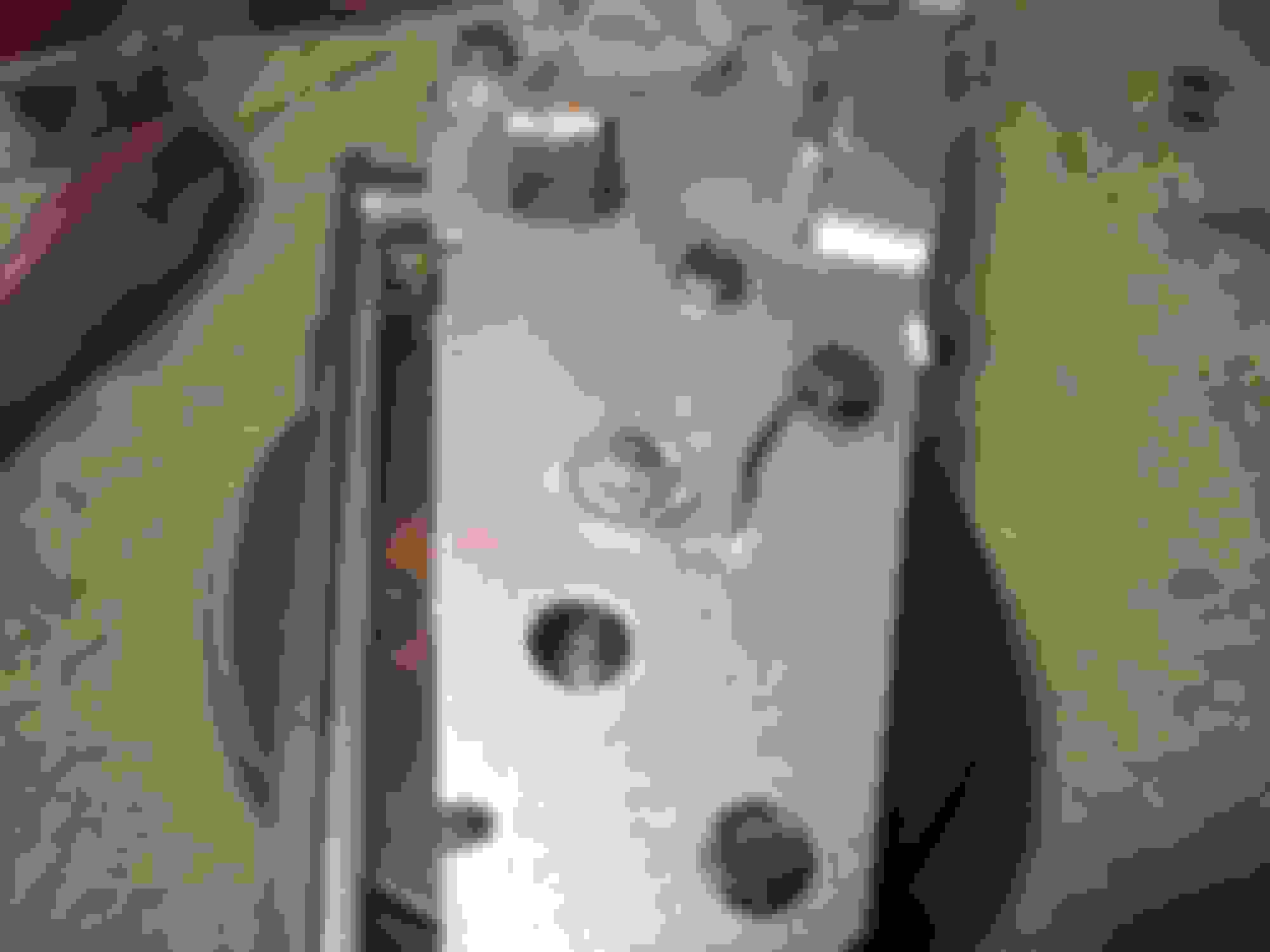
The cable sleeve gets fed through the side of the frame and a single bolt holds it in place
Is this what your after or do you mean where the actual cable (inner) connects to the control?
M
Last edited by Mooser; 04-19-2020 at 01:57 PM.
Reason: fix photobucket mess
The cable sleeve gets fed through the side of the frame and a single bolt holds it in place
Is this what your after or do you mean where the actual cable (inner) connects to the control?
M
Man Moose....you saved my bacon with those pictures. After looking them over I finally got to work on my Vette today and everything is connected and working.
I appreciate you taking the time to post those pics.

 04-24-2015, 05:19 PM