
Plastic Fantastic tew
 03-23-2018, 09:06 PM
#141
Nam Labrat


Member Since: Sep 2013
Location: New Orleans Loo-z-anna
Posts: 33,893
Received 4,173 Likes
on
2,735 Posts

That hood will be intake manifold/carb friendly! 
 03-26-2018, 12:09 AM
#142
Melting Slicks

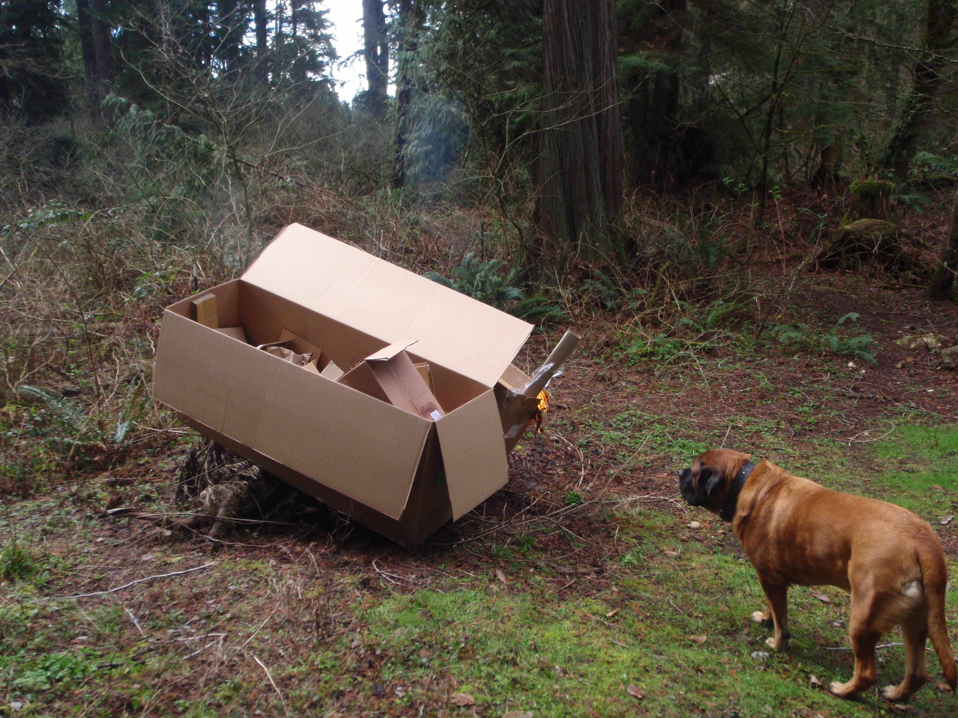
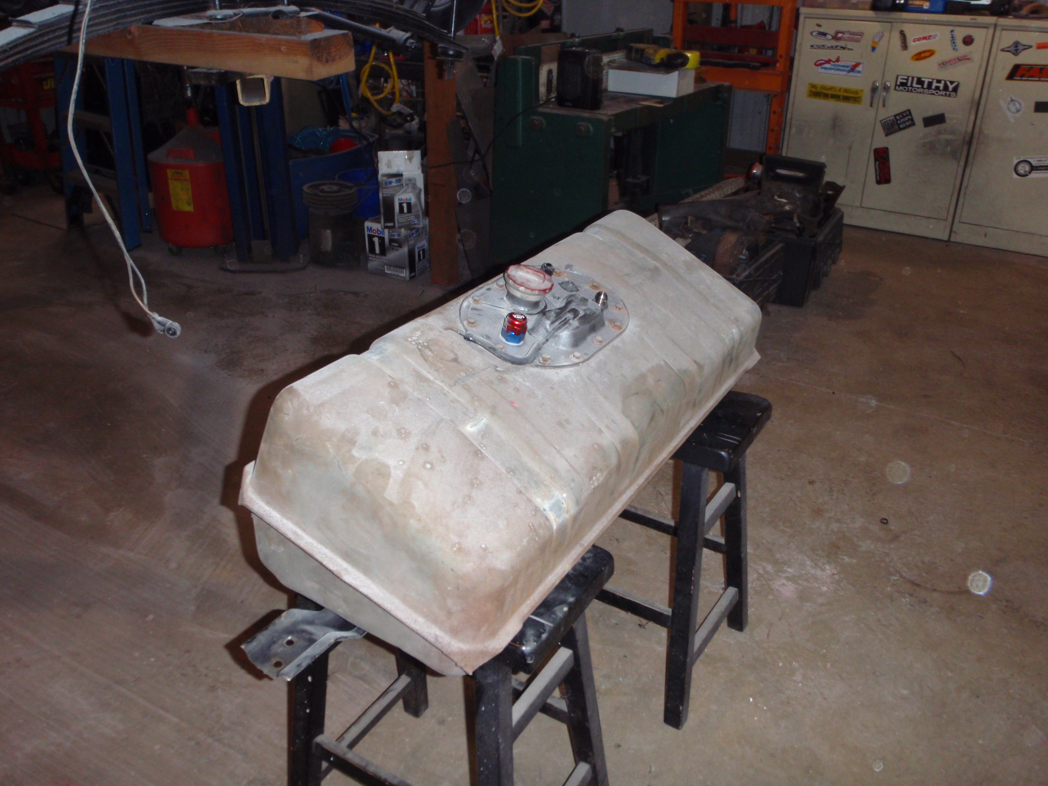
As much as I'd love to keep boxes like this around - there just isn't the room.... Buick seems okay with it
remove bolts
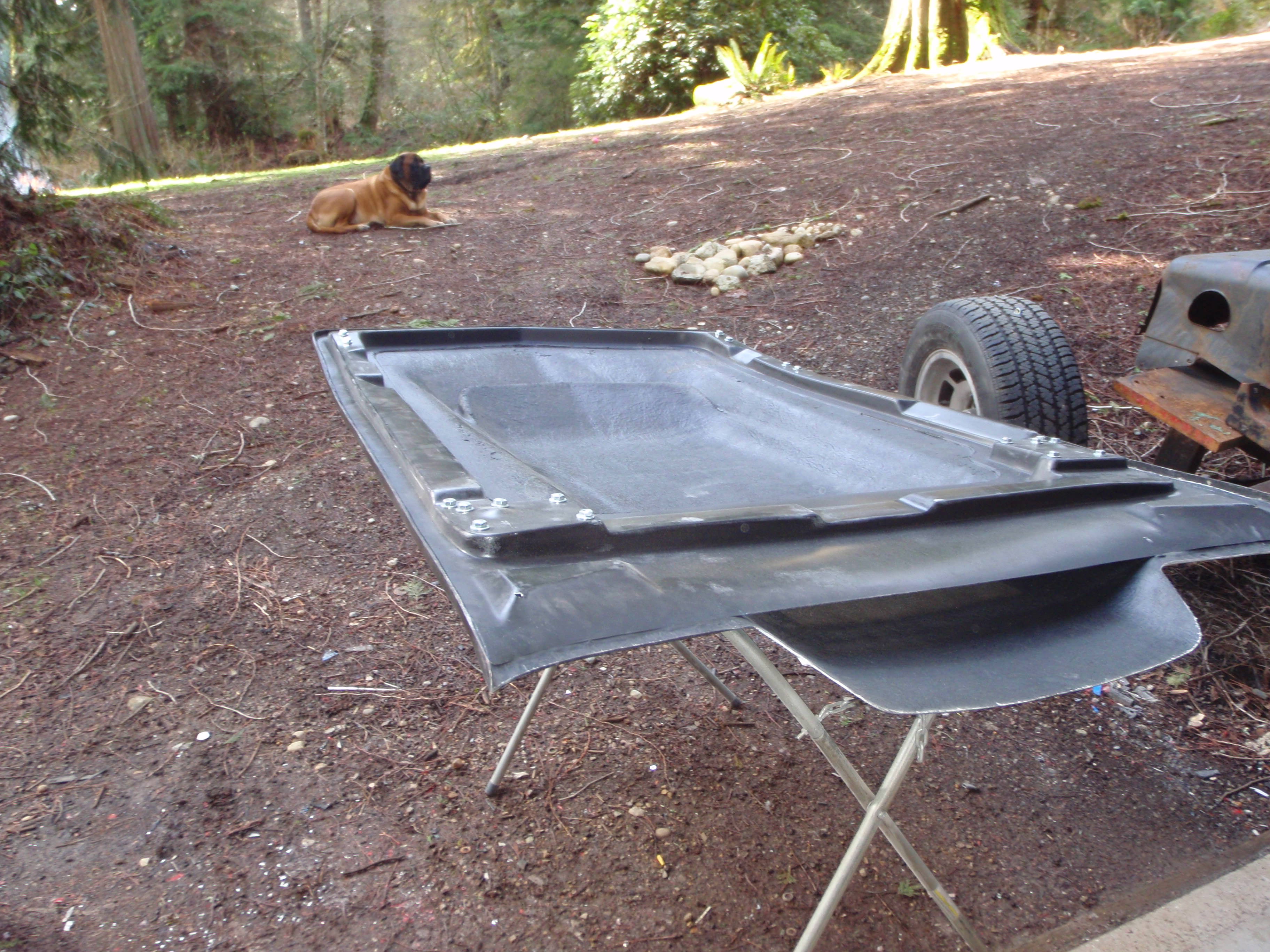
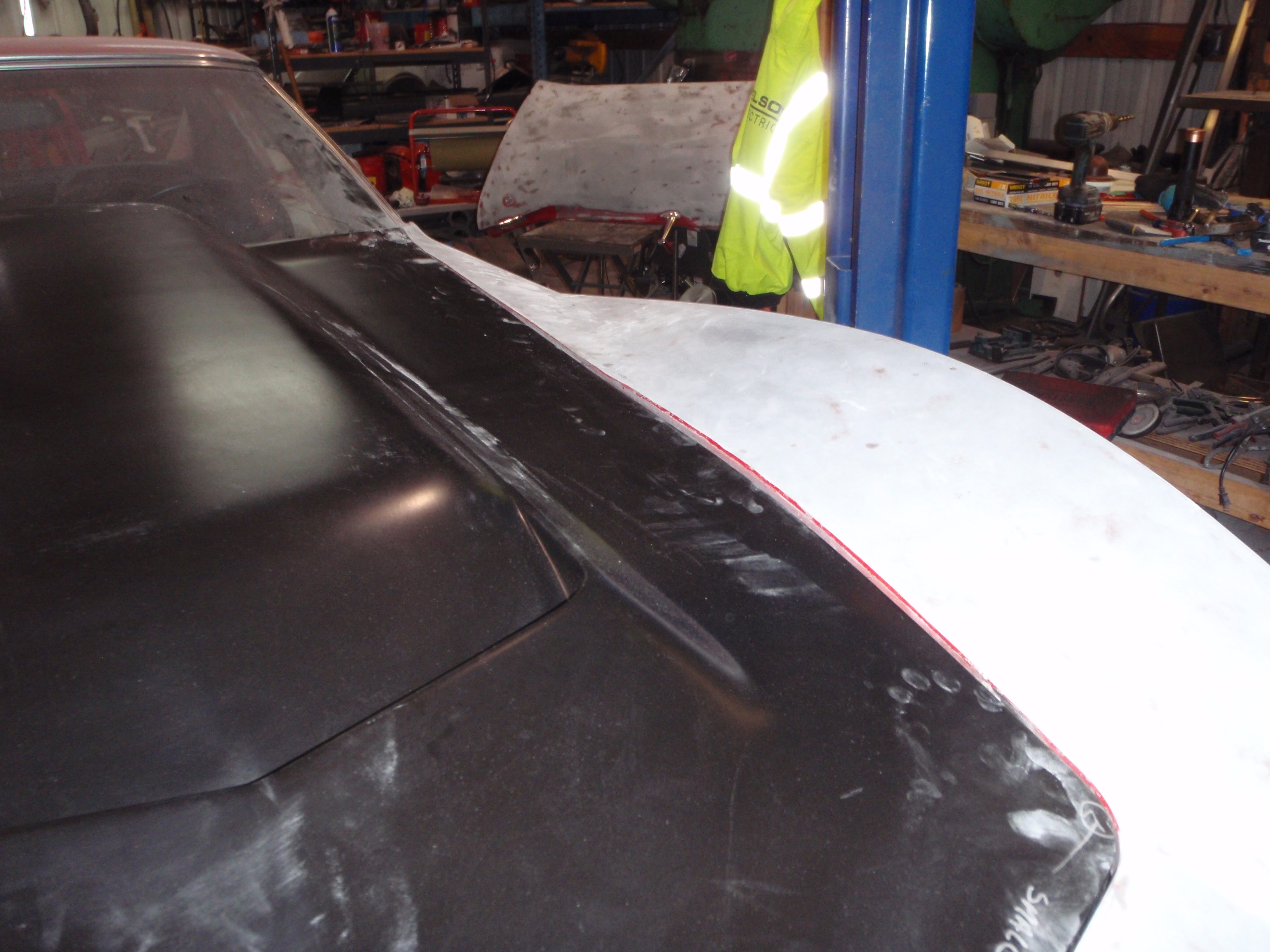
try fitting for real... ugh
better
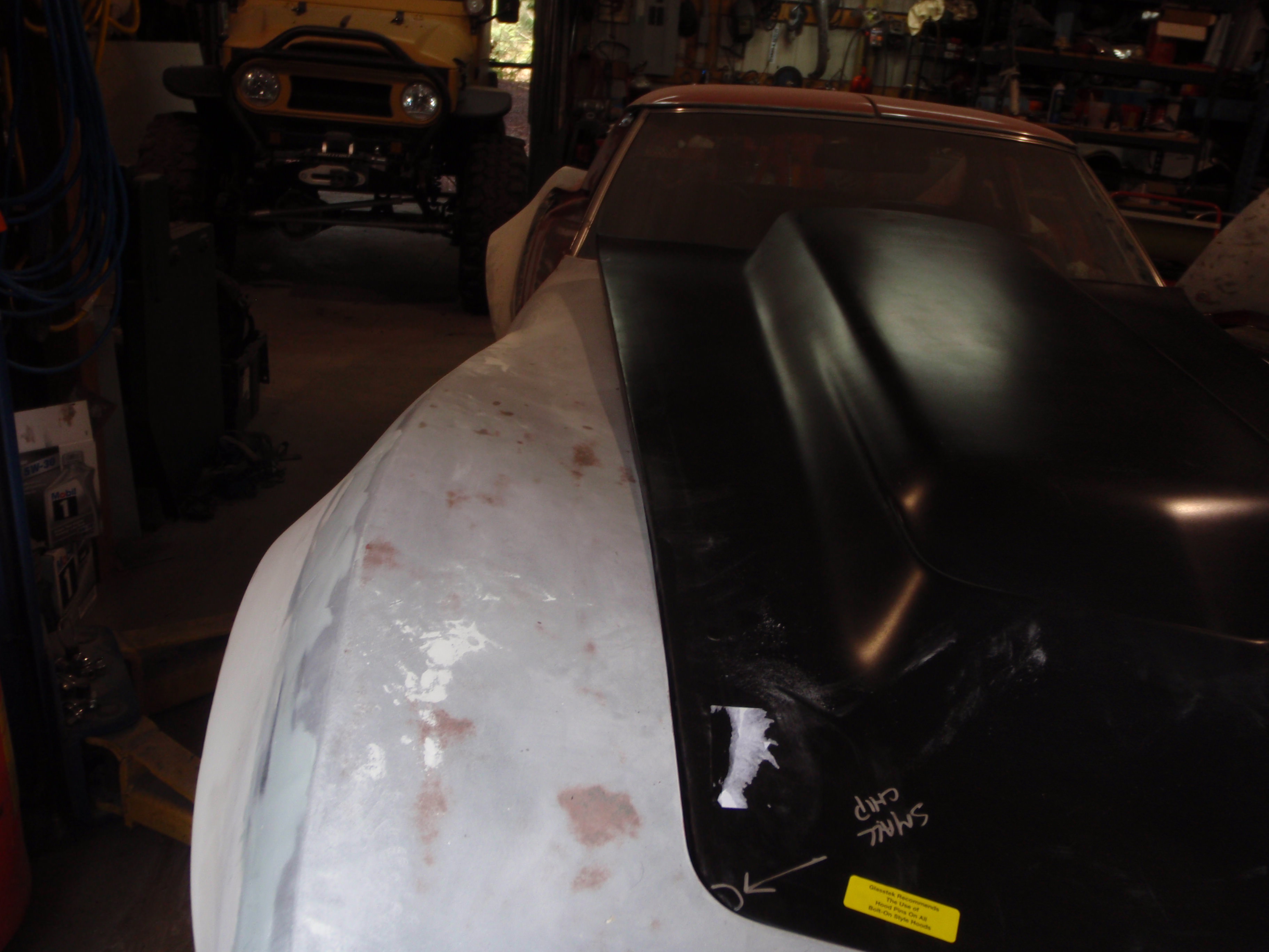
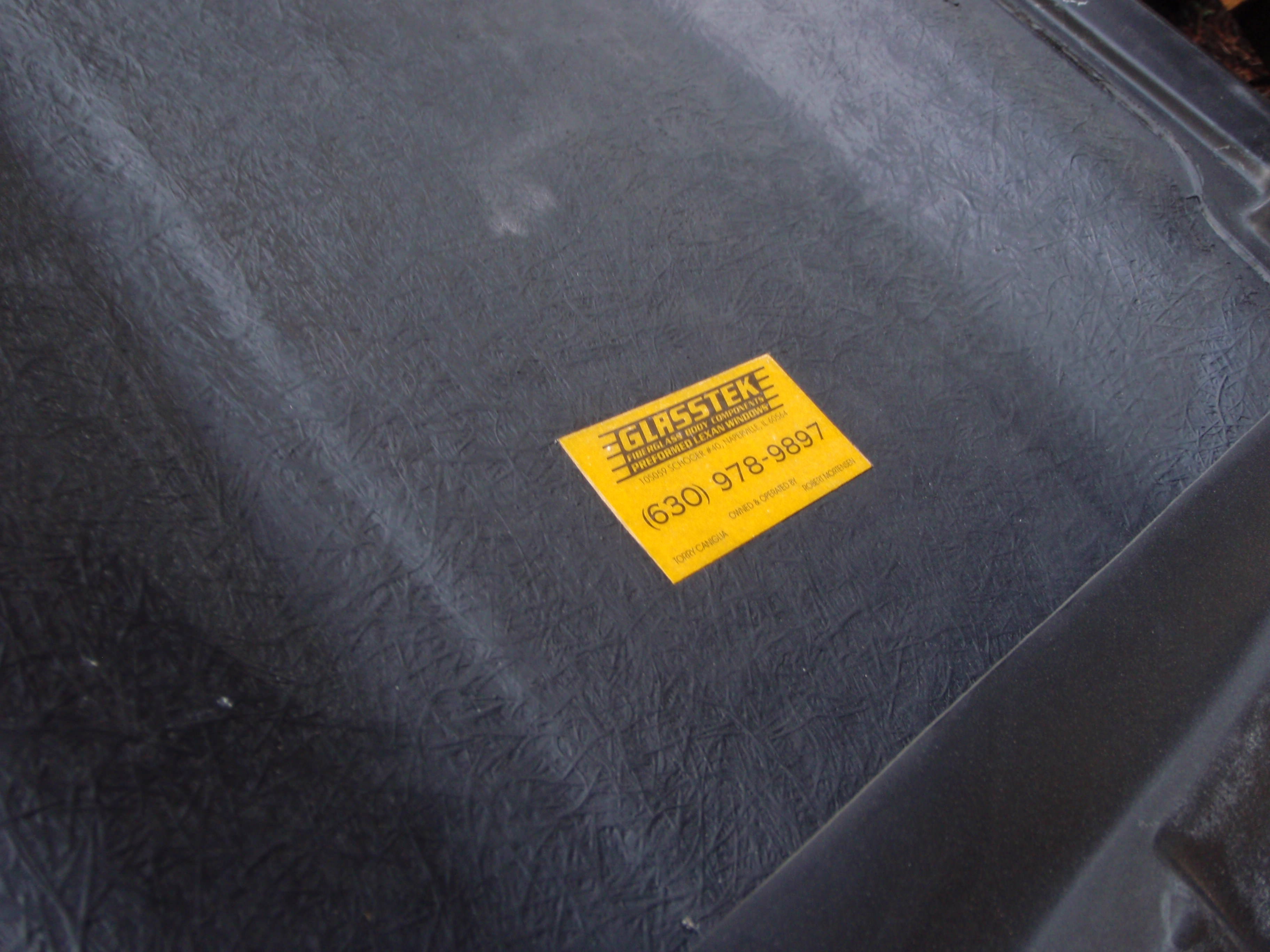
if anyone is curious who made it
notsobetter - I solved this with heat.... pictures tomorrow.
oh you must be kidding me - need to drill out the support to 5/16
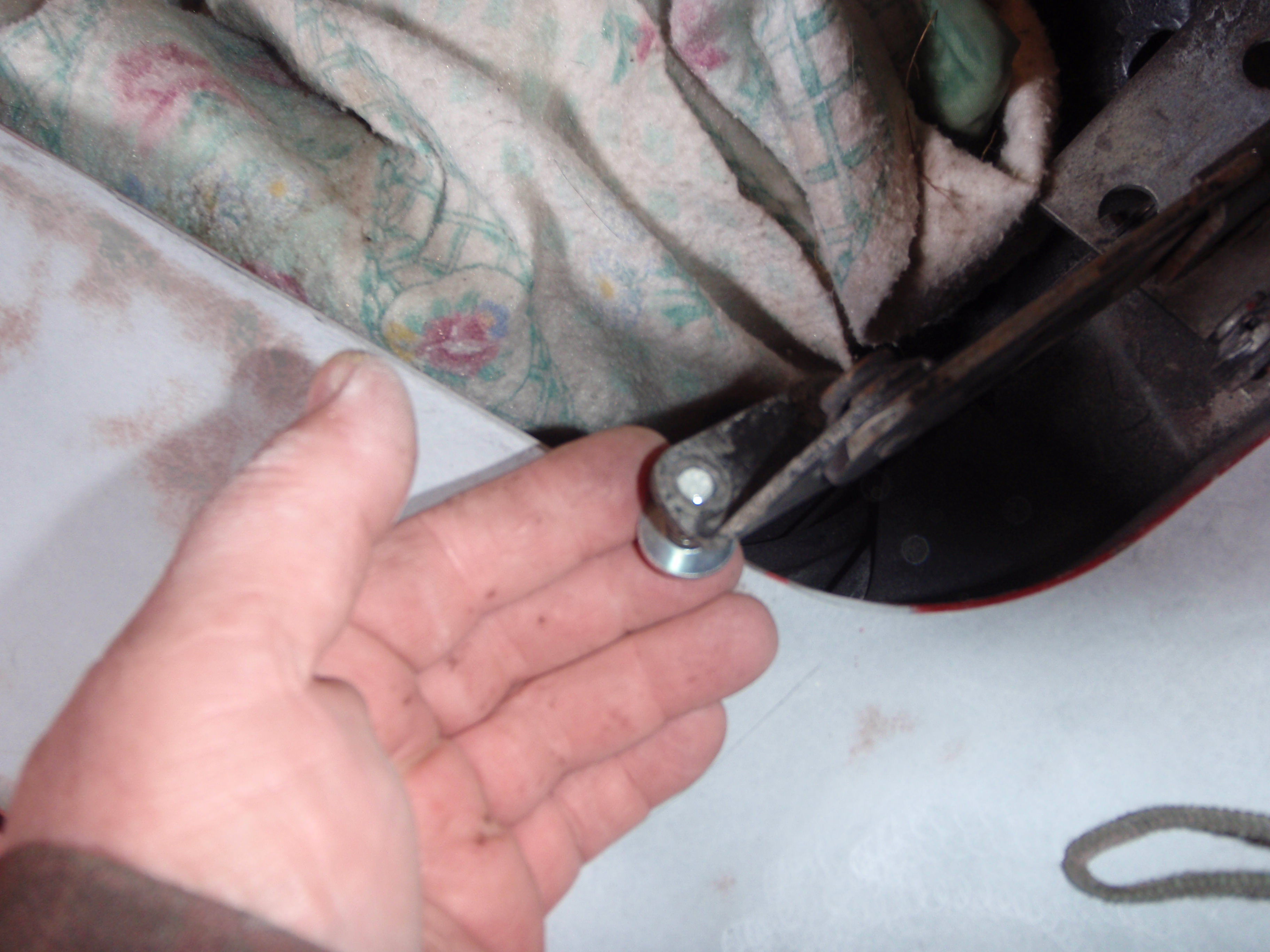
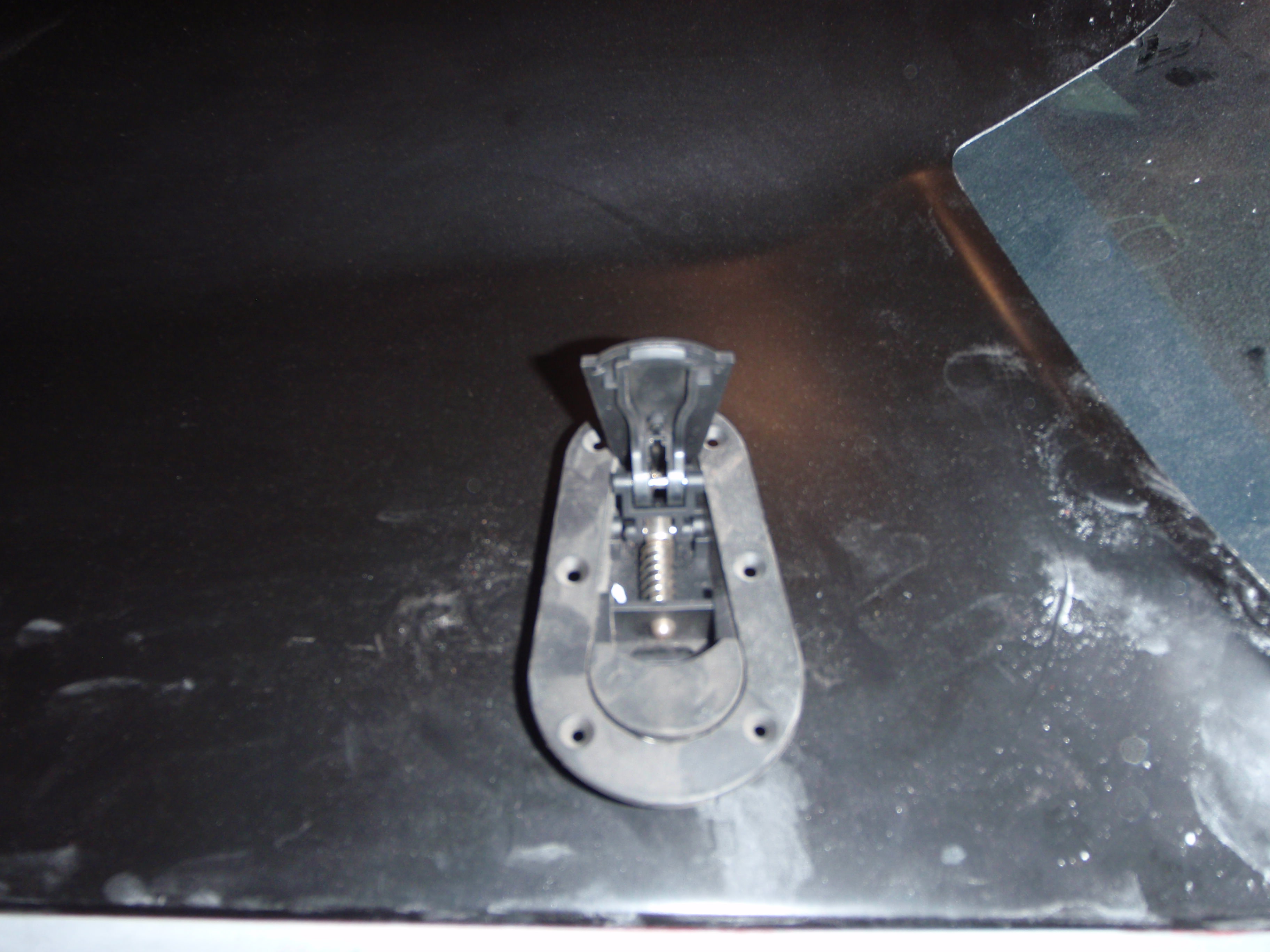
they suggest hood pins.... I have hood pins
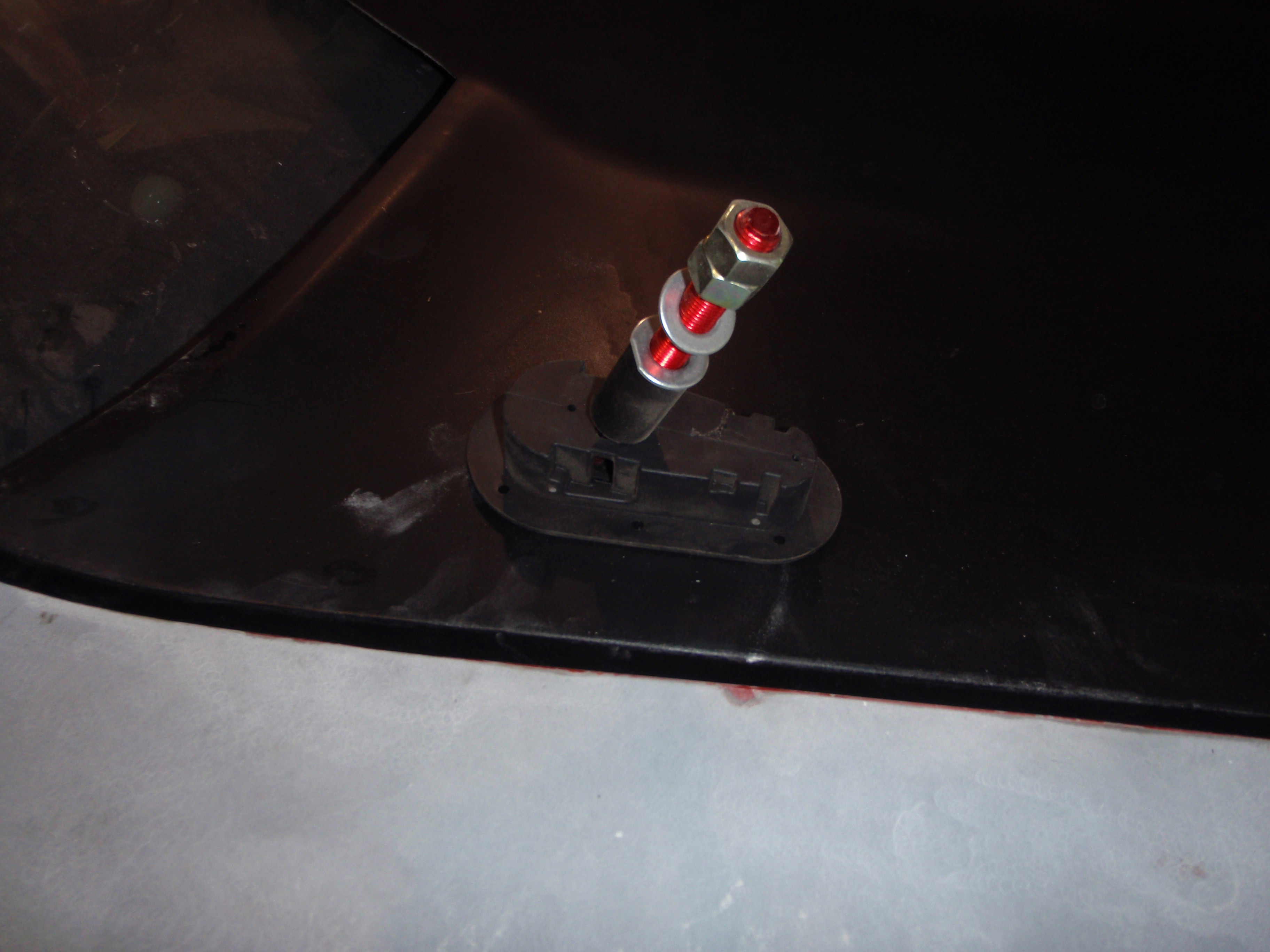
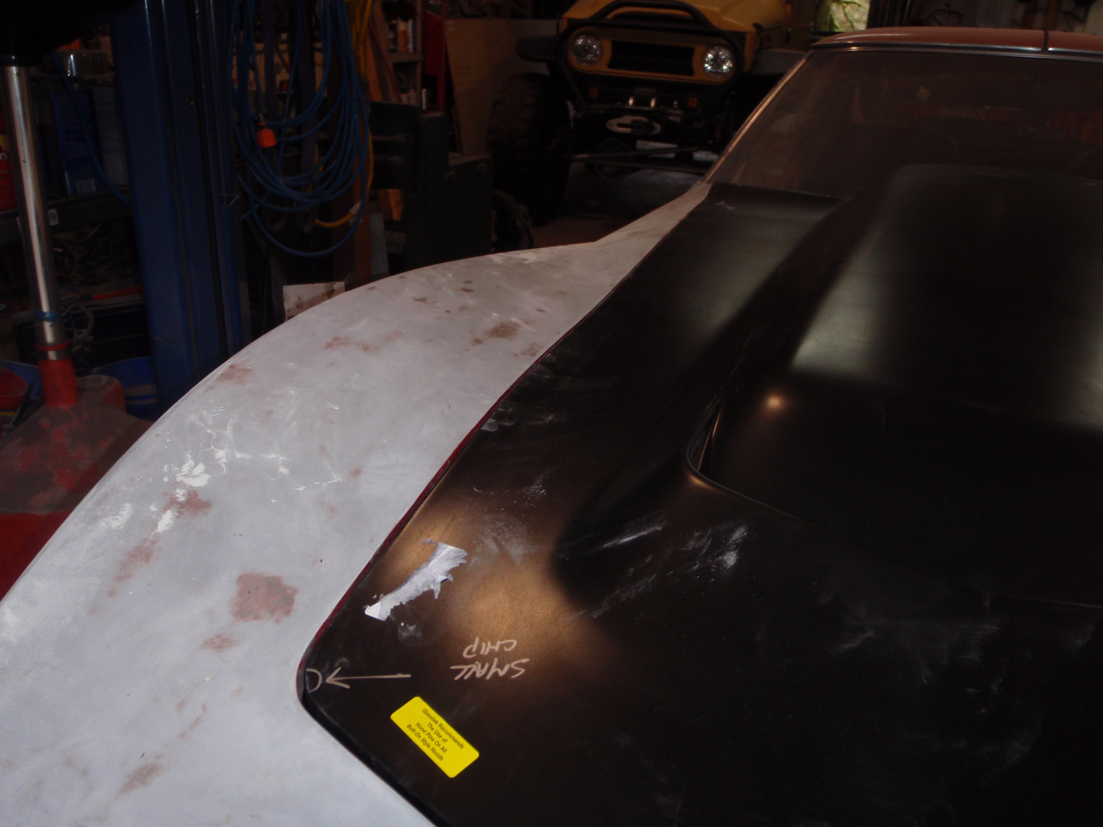
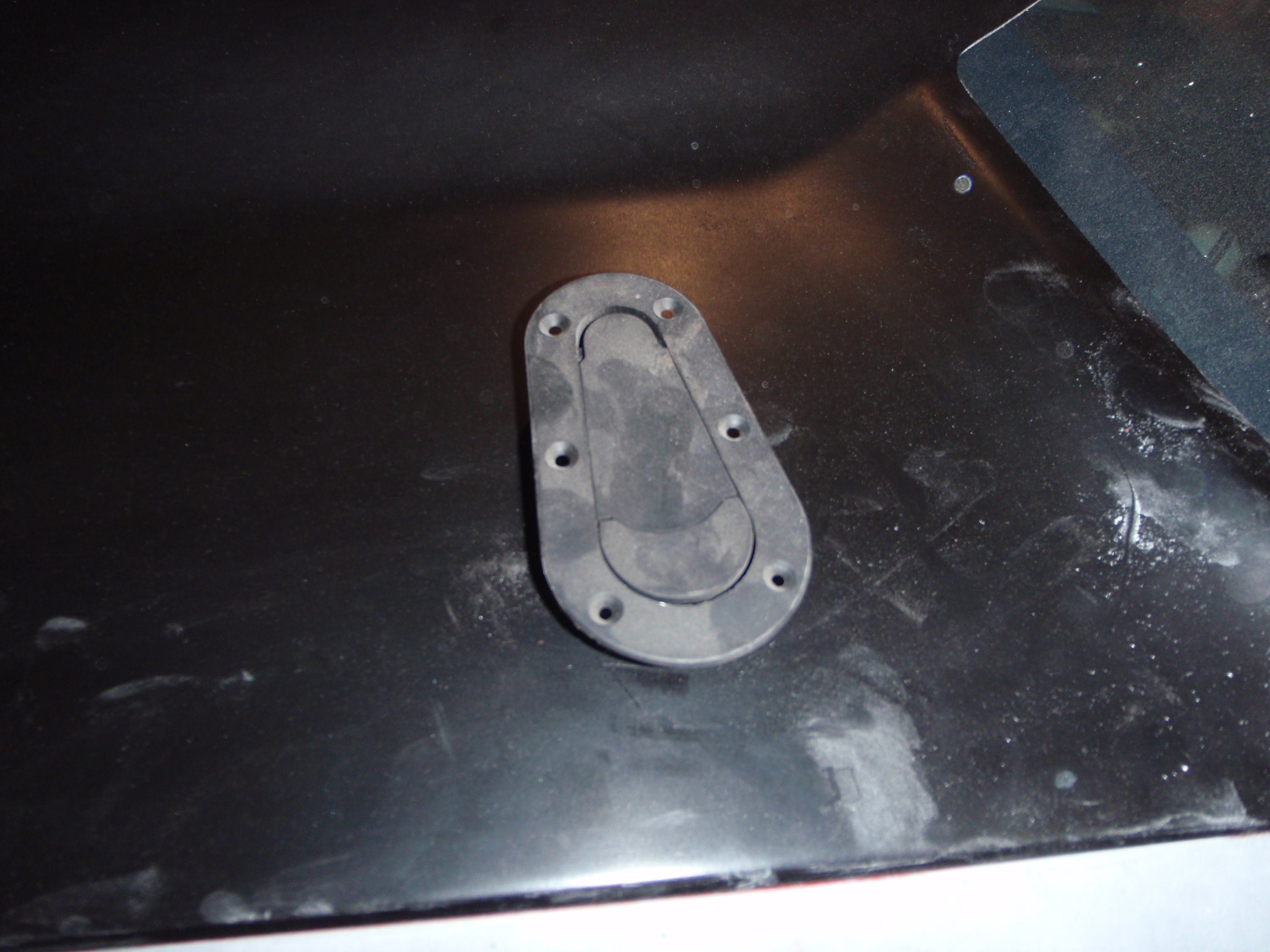
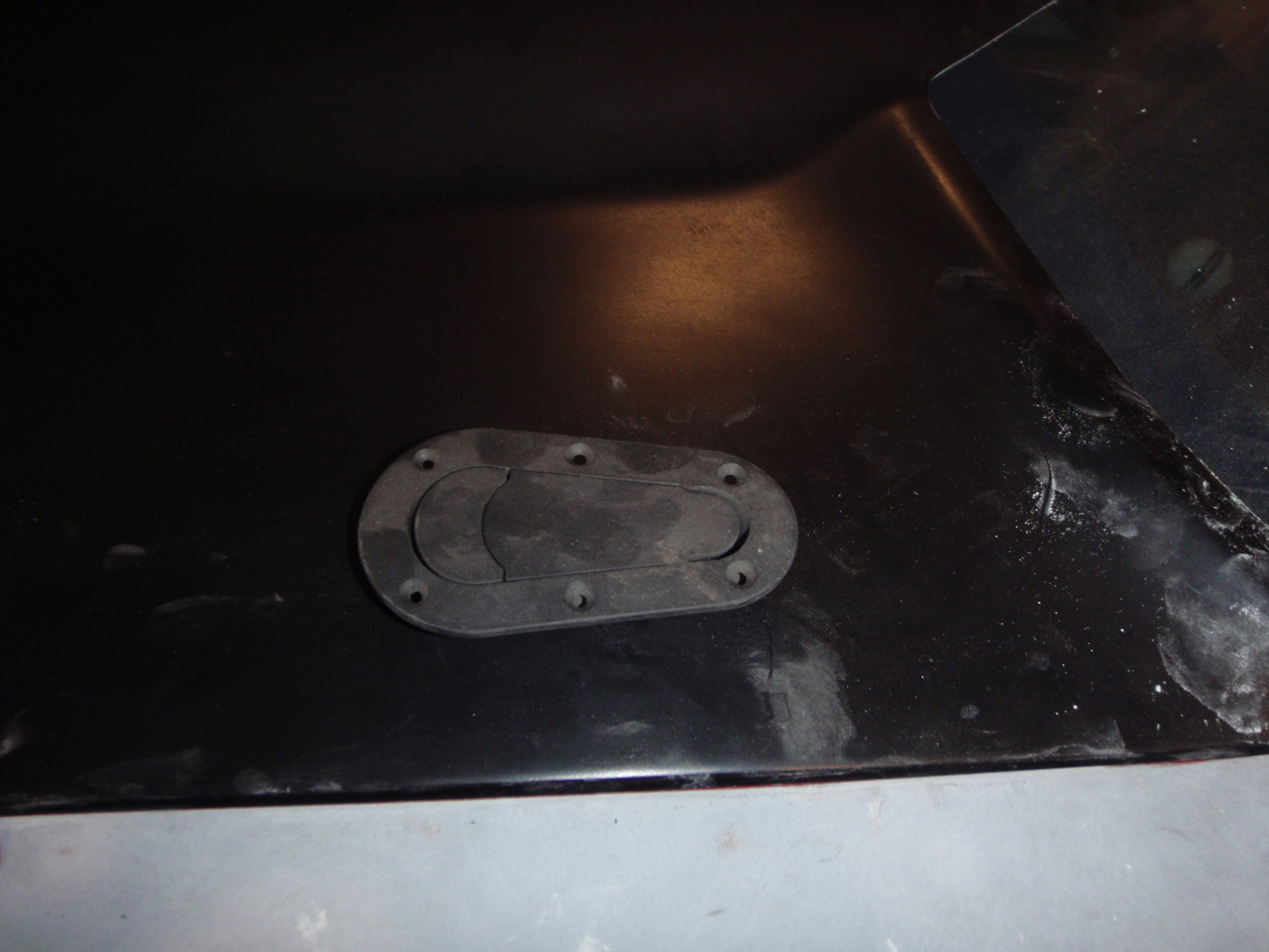
schnazzy, no?
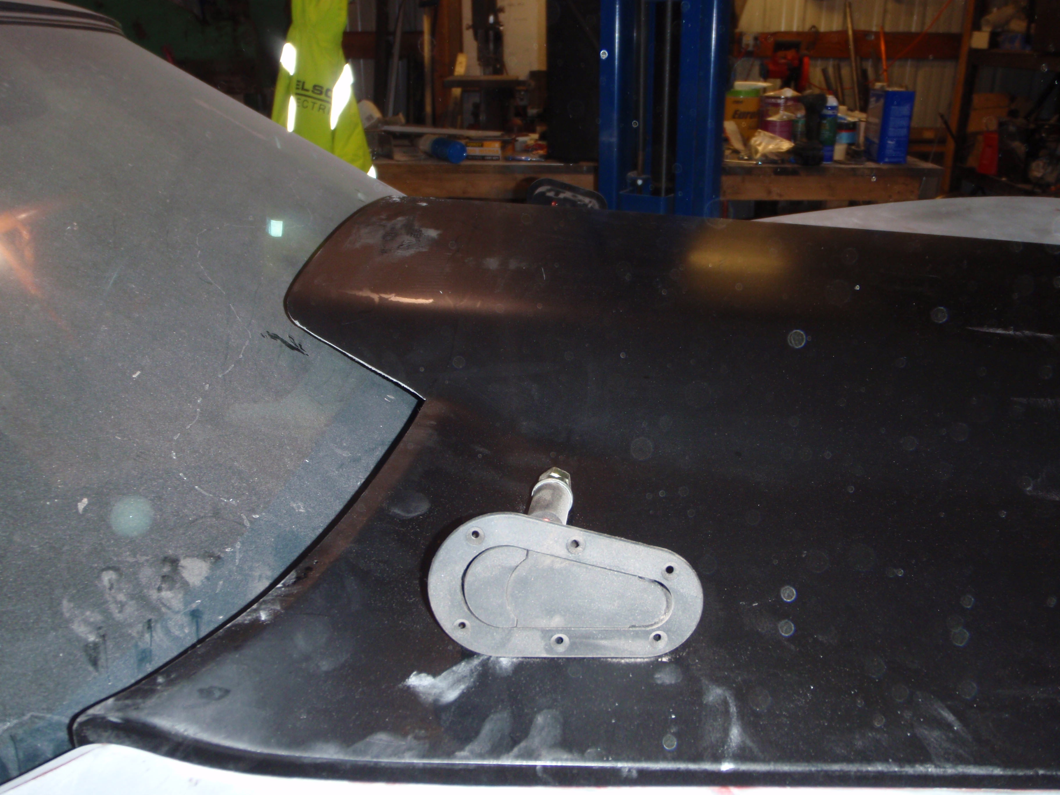
I'd love to move it closer to the windshield but the pins would go straight through the wiper pivot
wonder how much faster it would be if I turned them to flow with the wind?
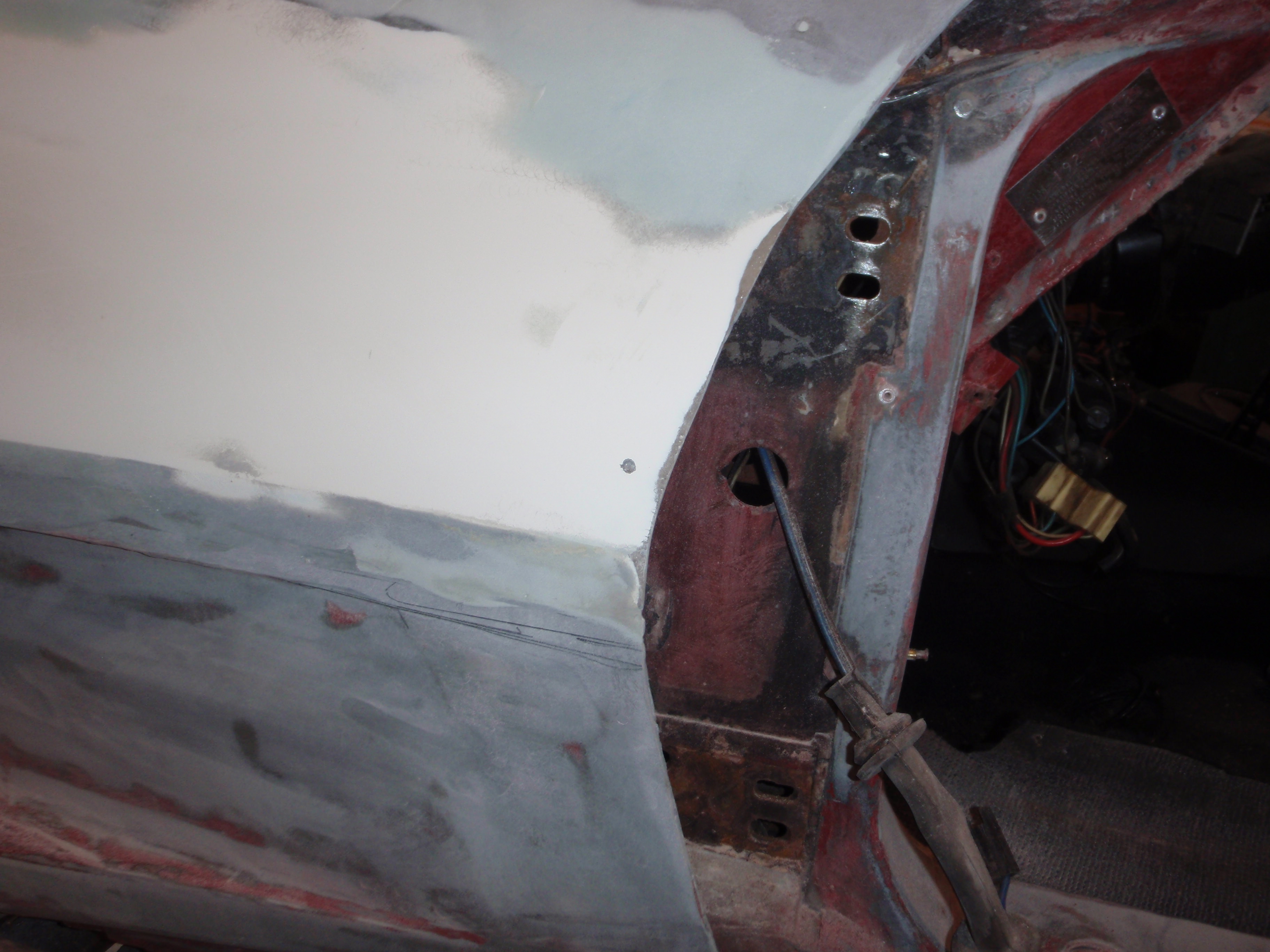
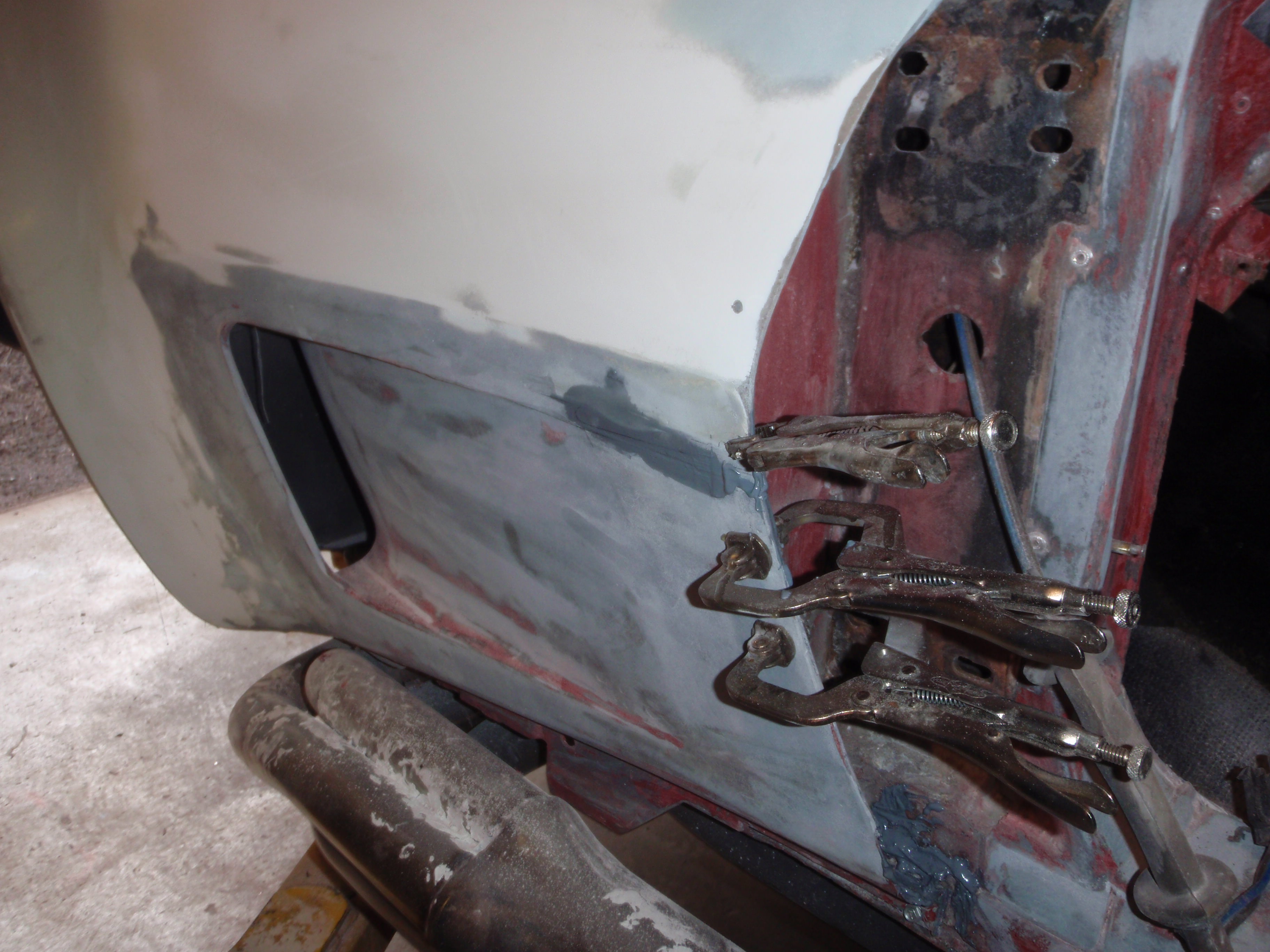
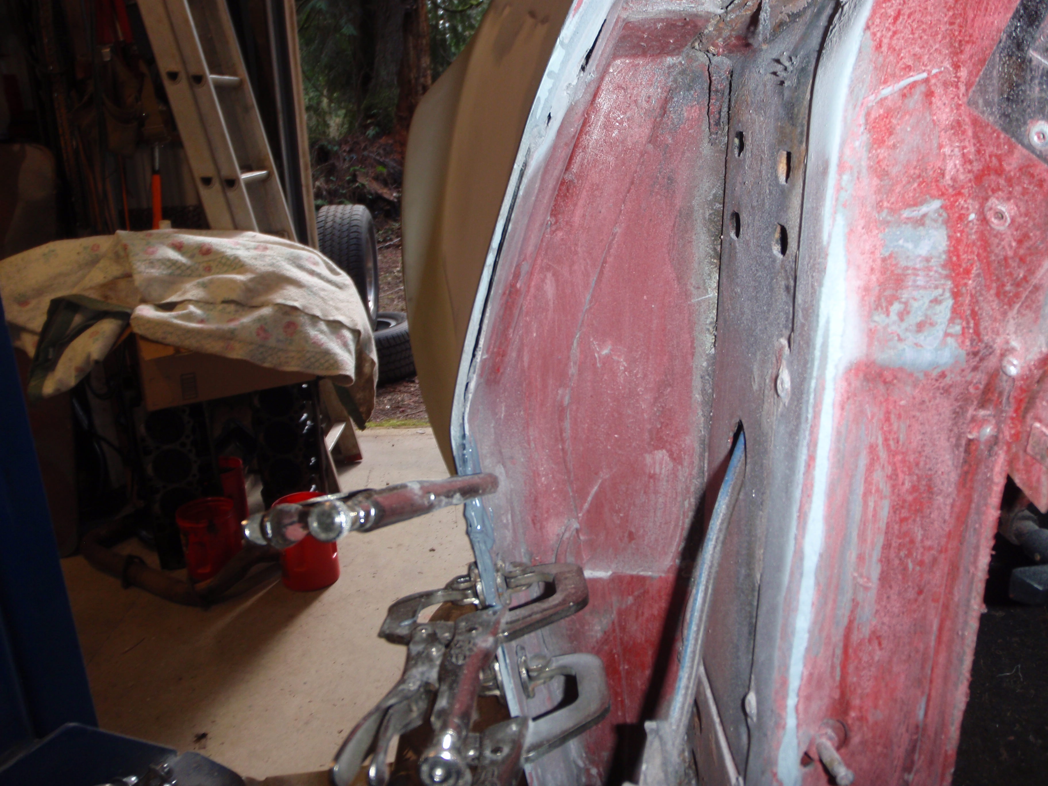
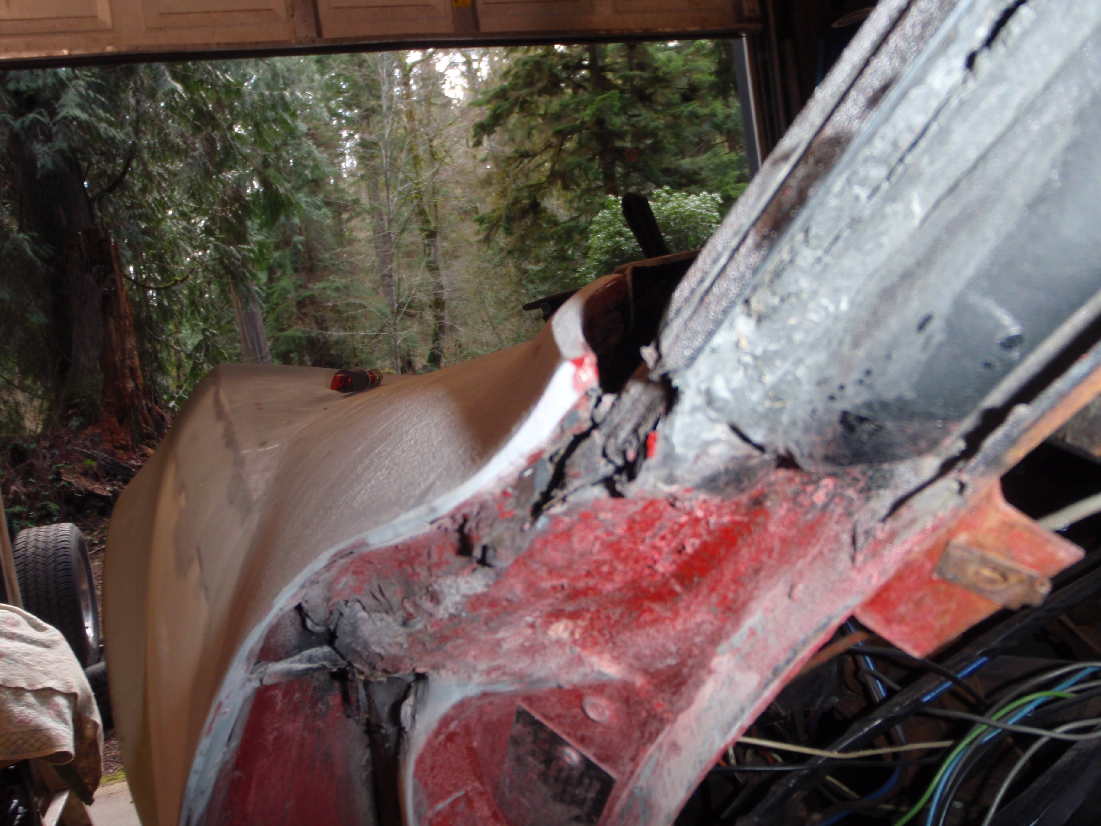
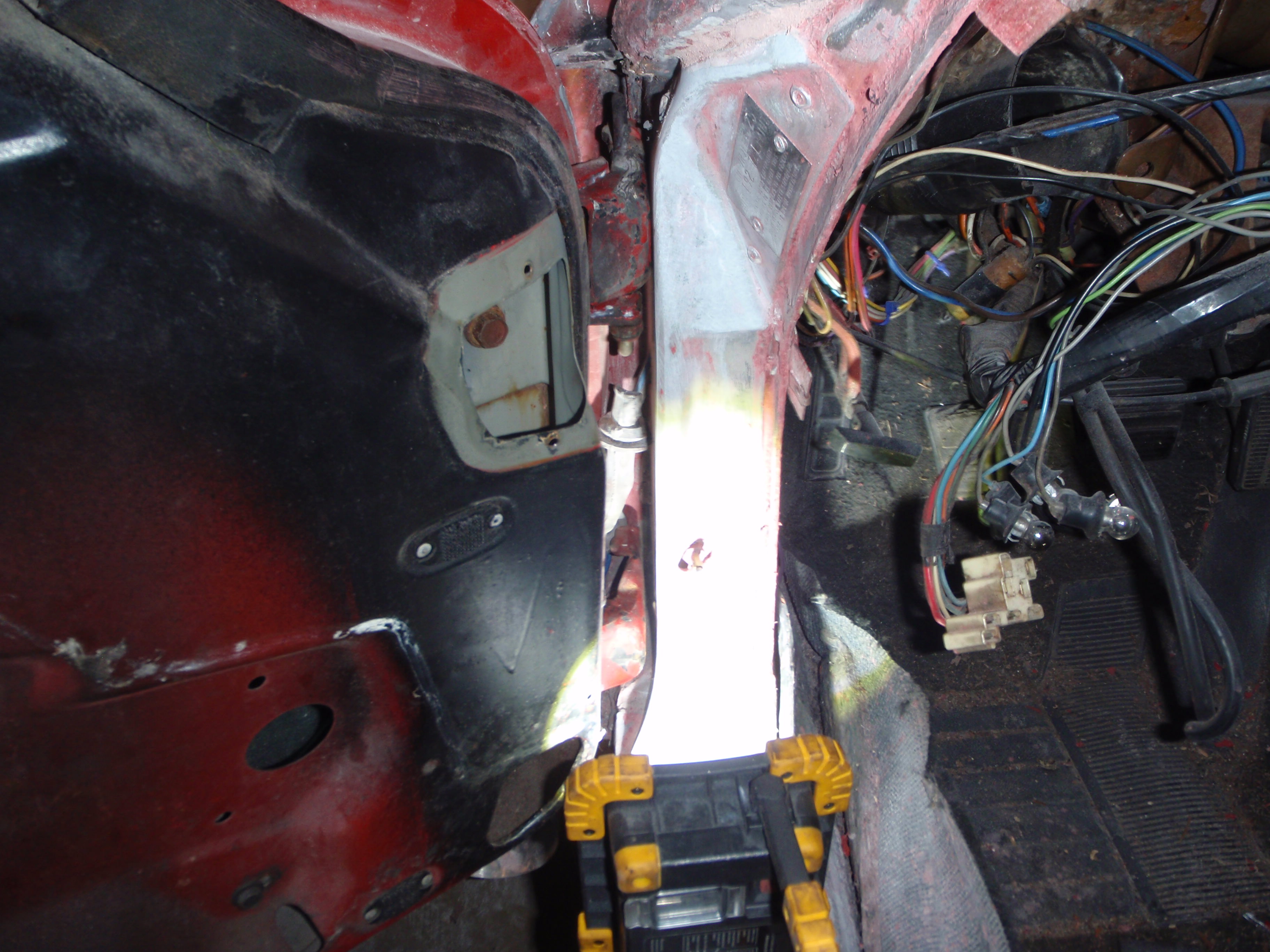
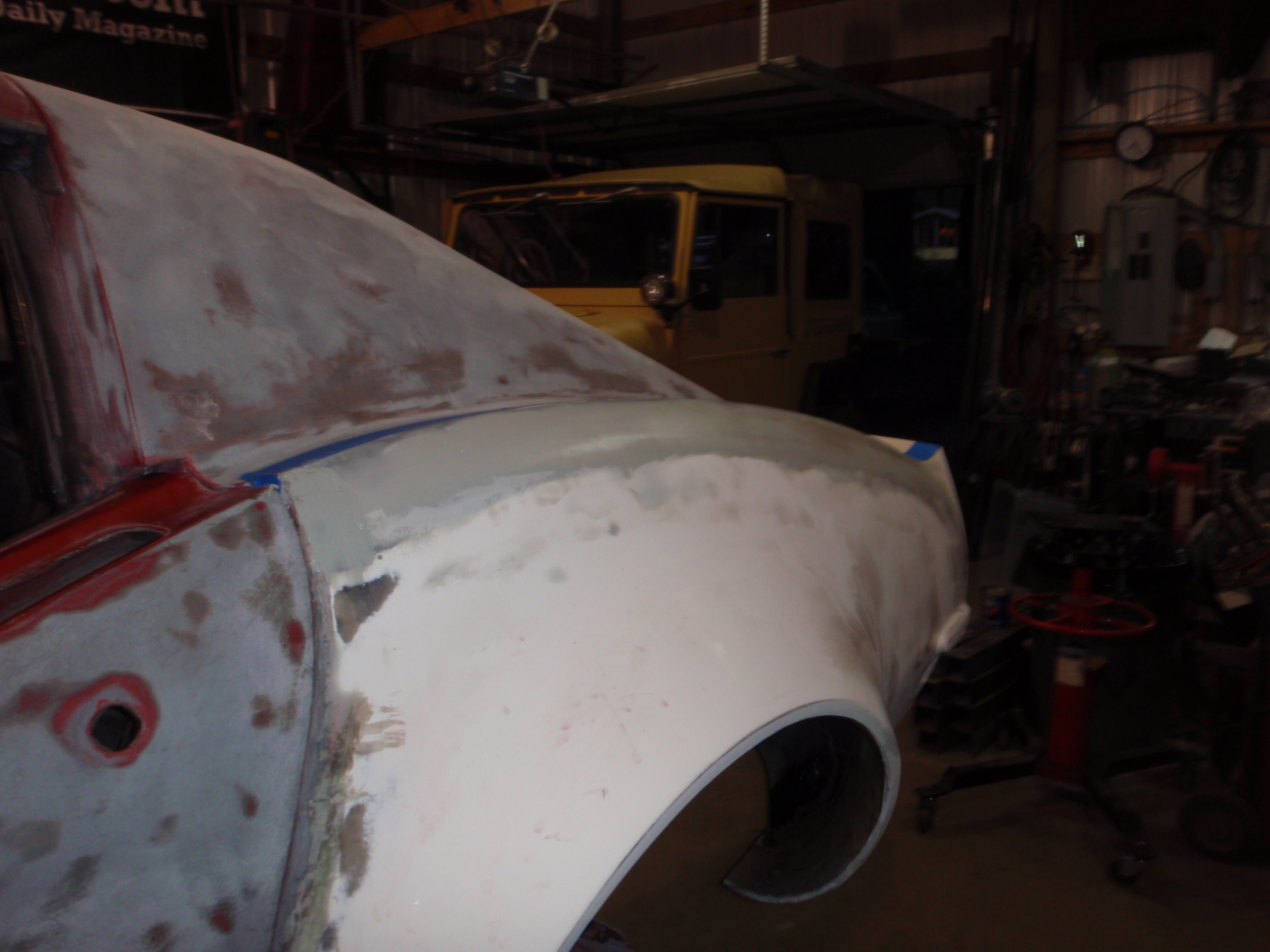
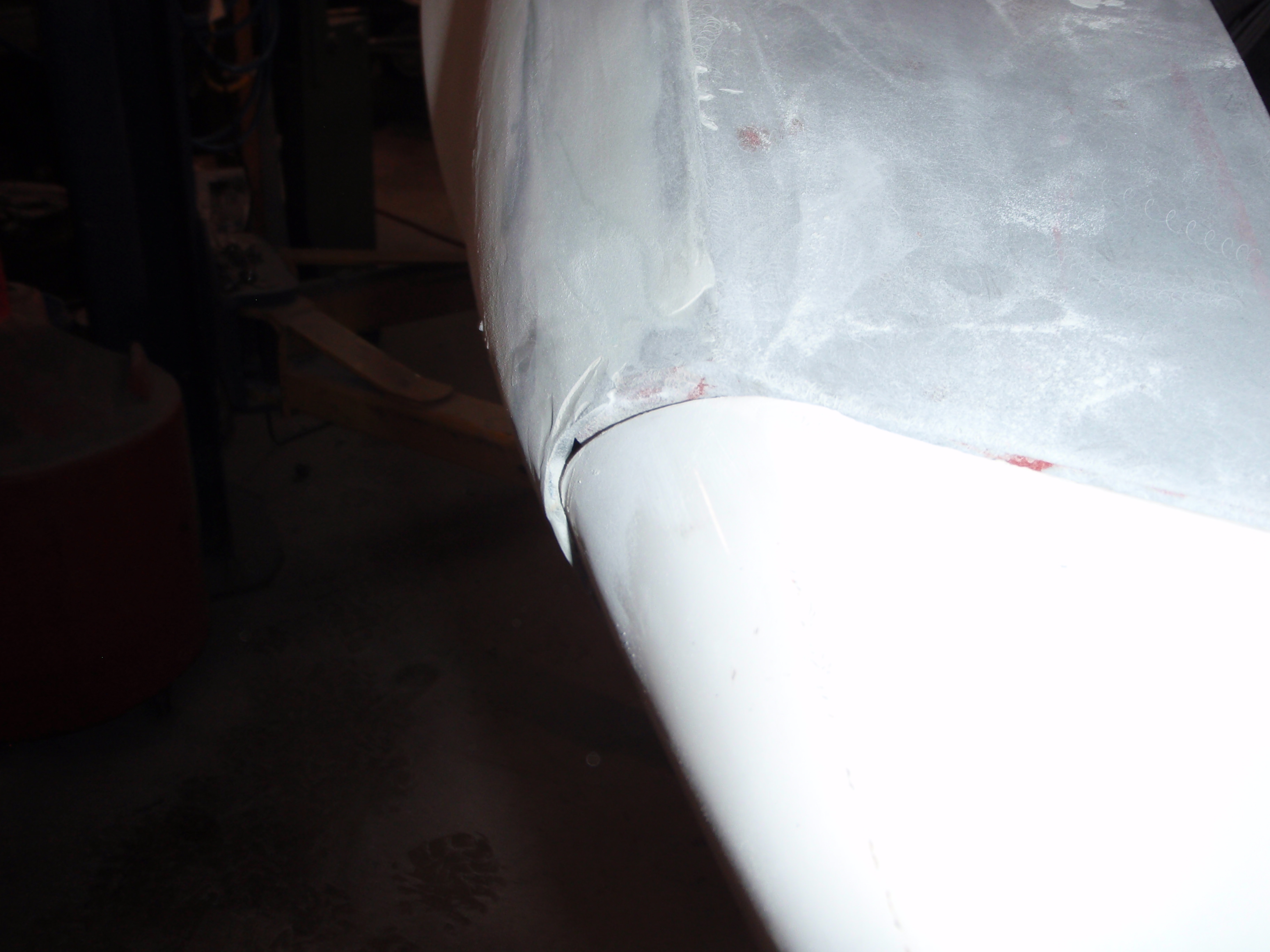
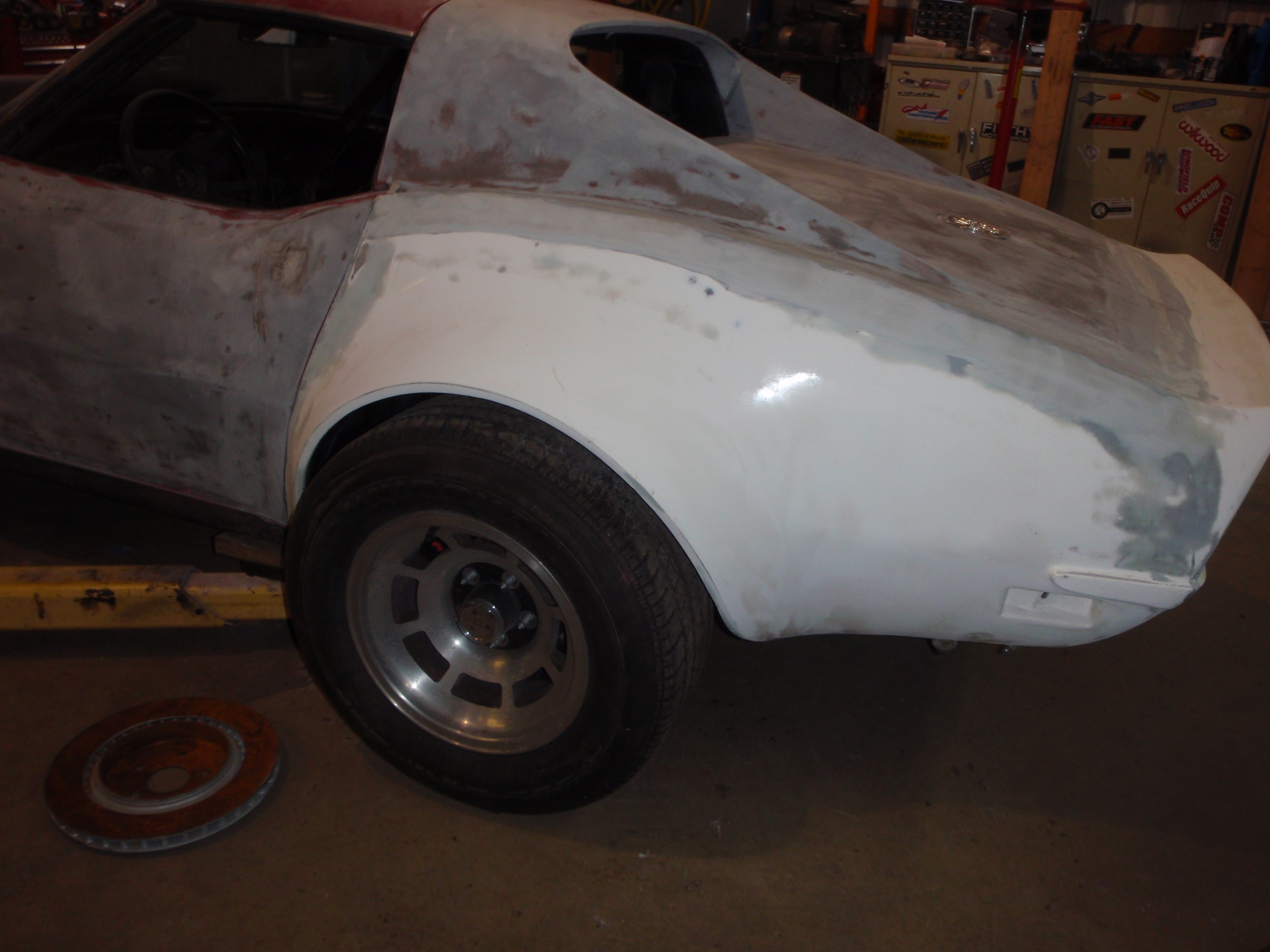
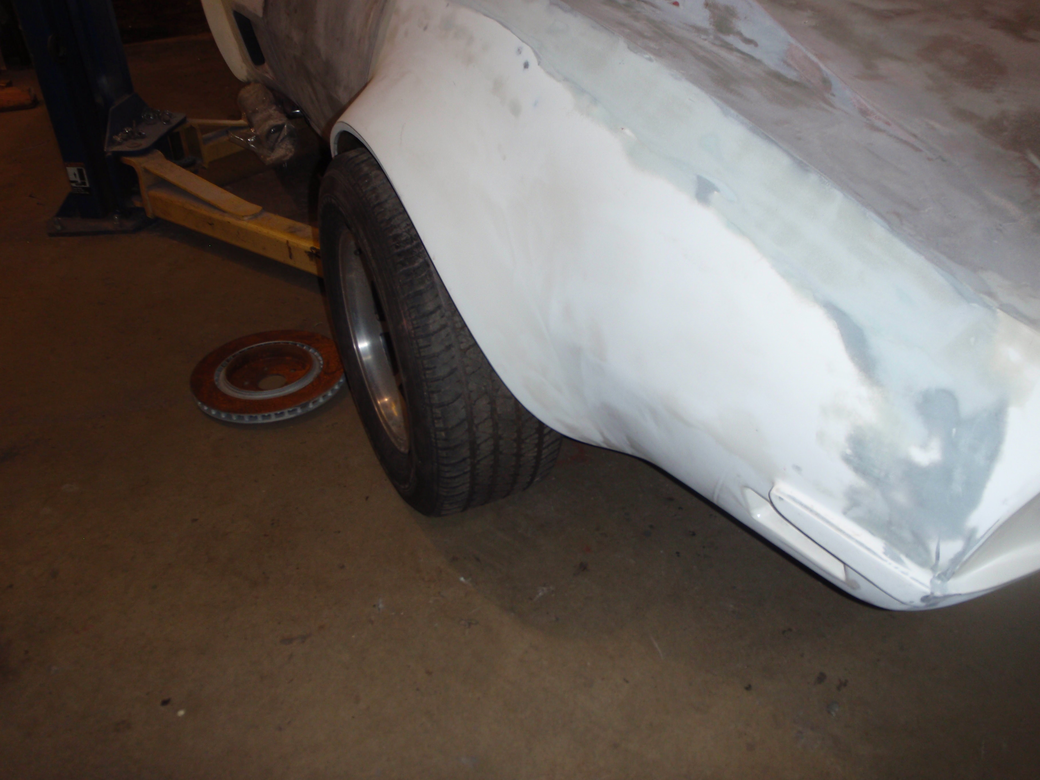
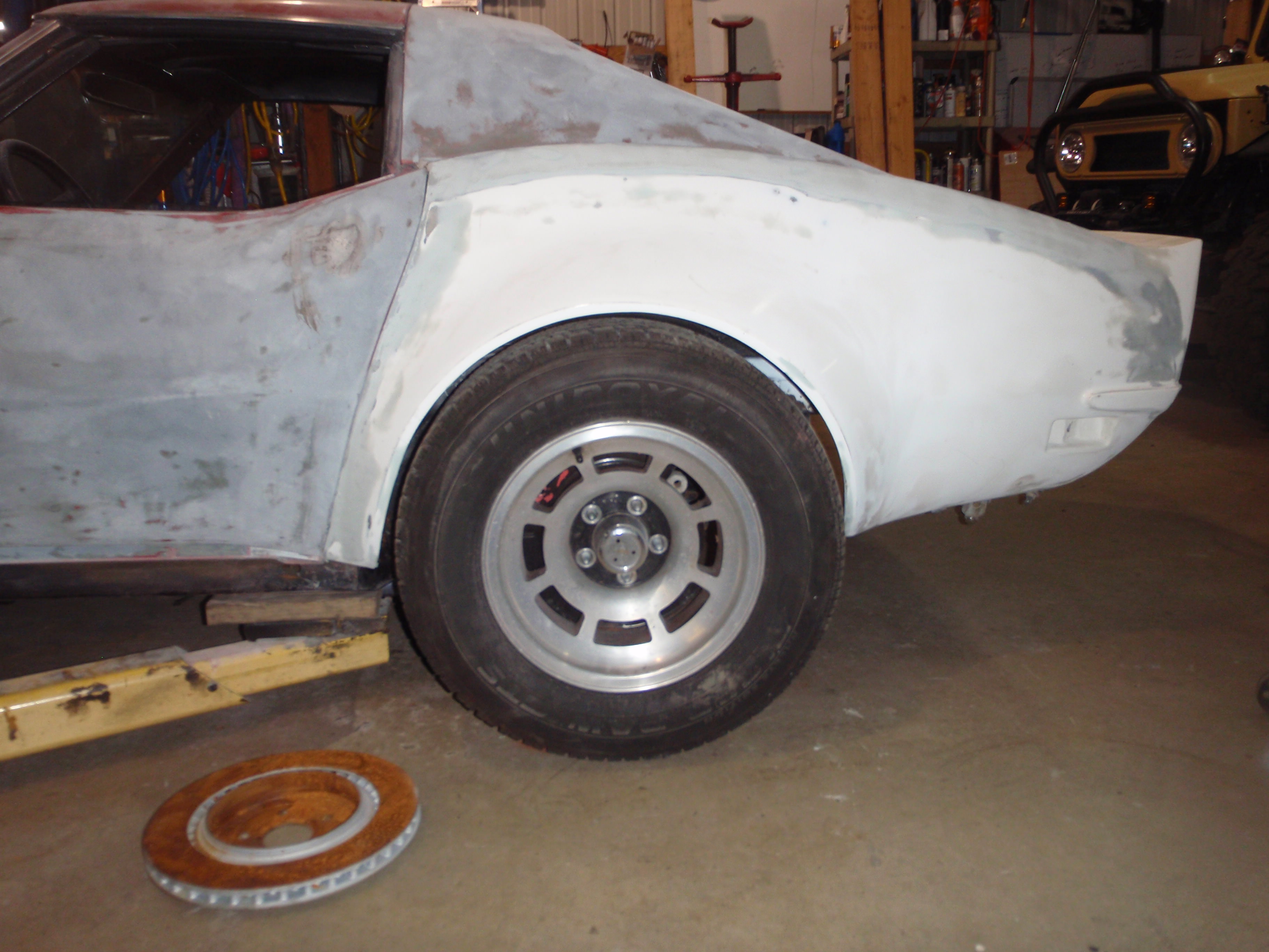
onto other issues.... non-adherence of the fender
cut, glue, clamp fixeded
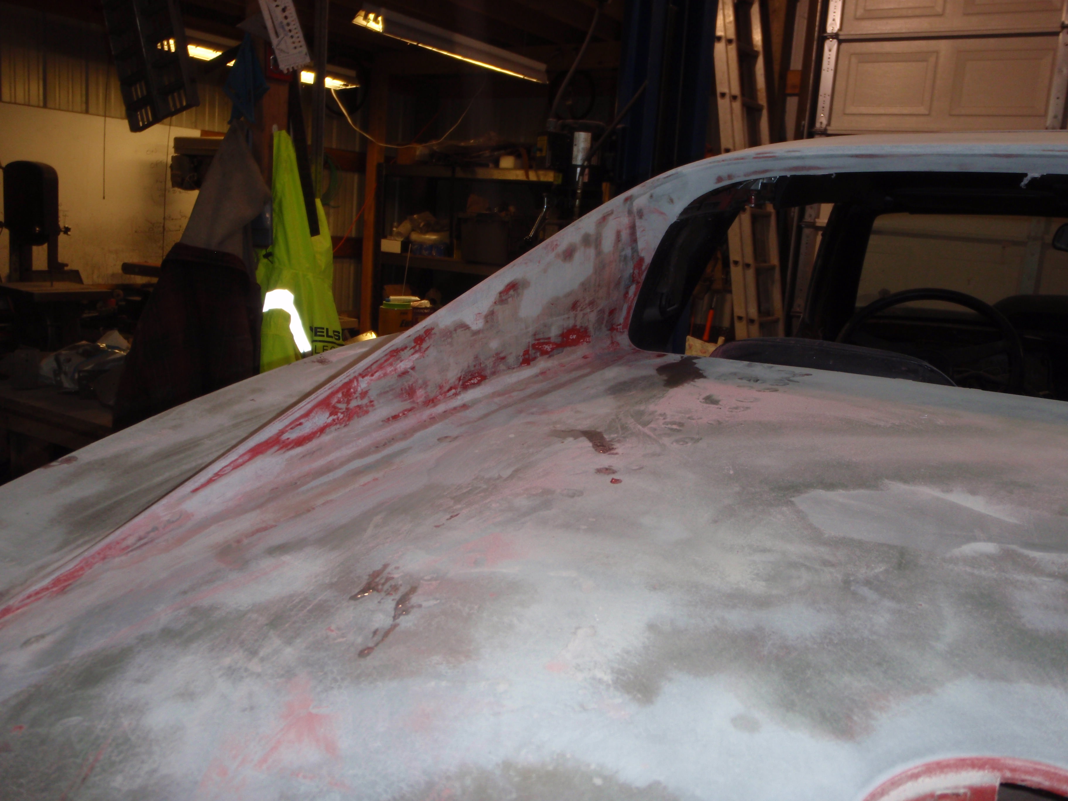
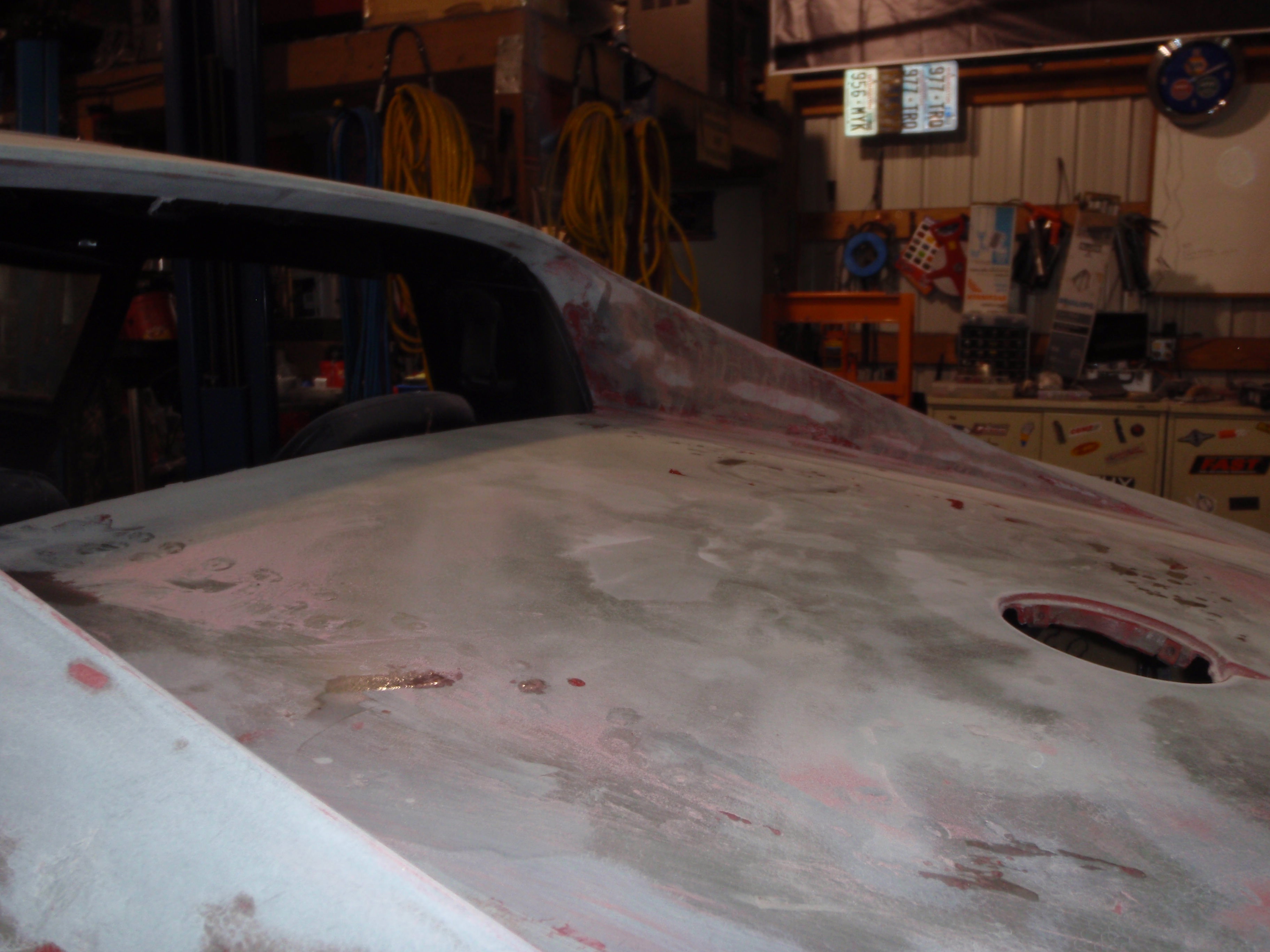
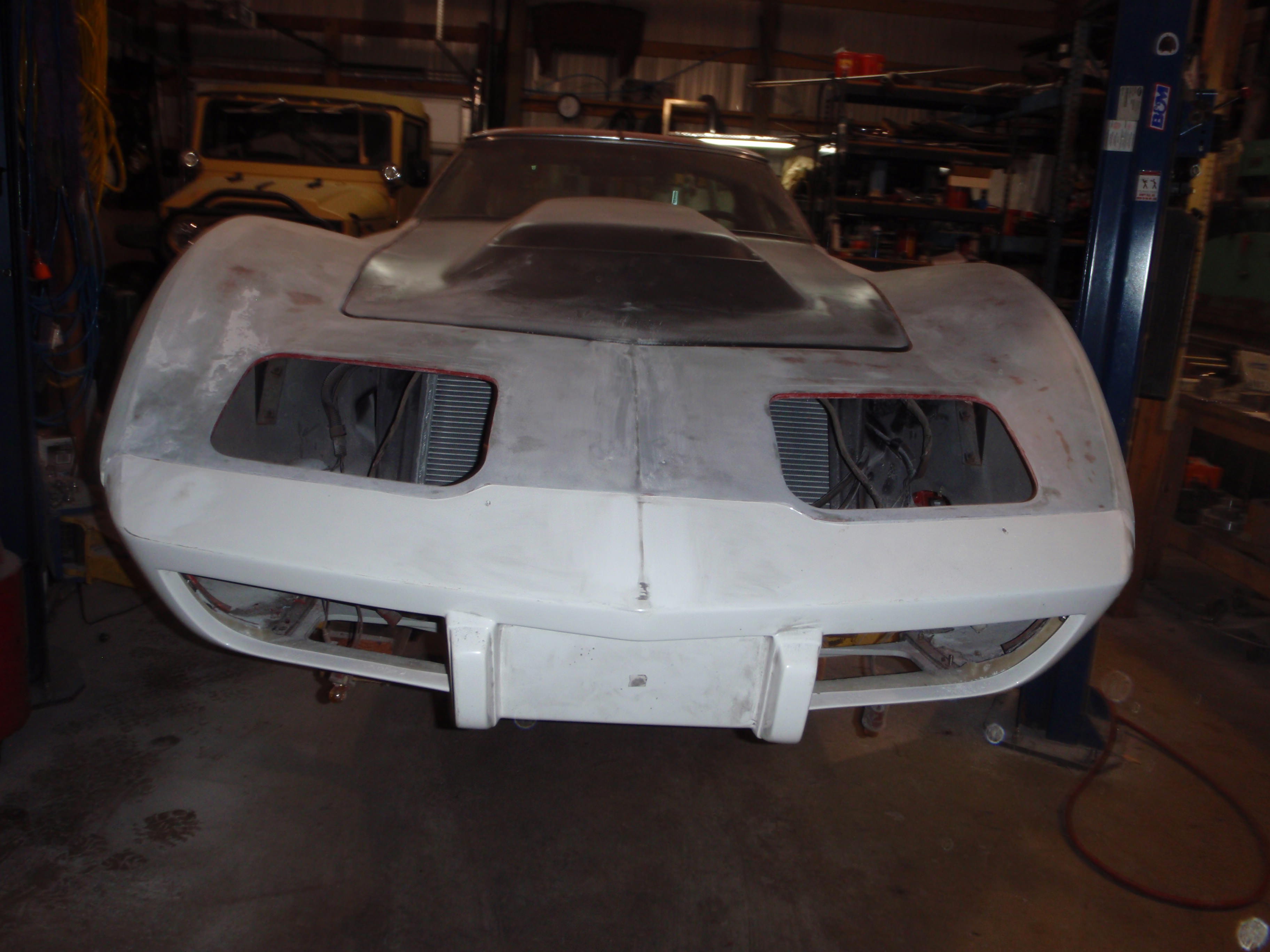
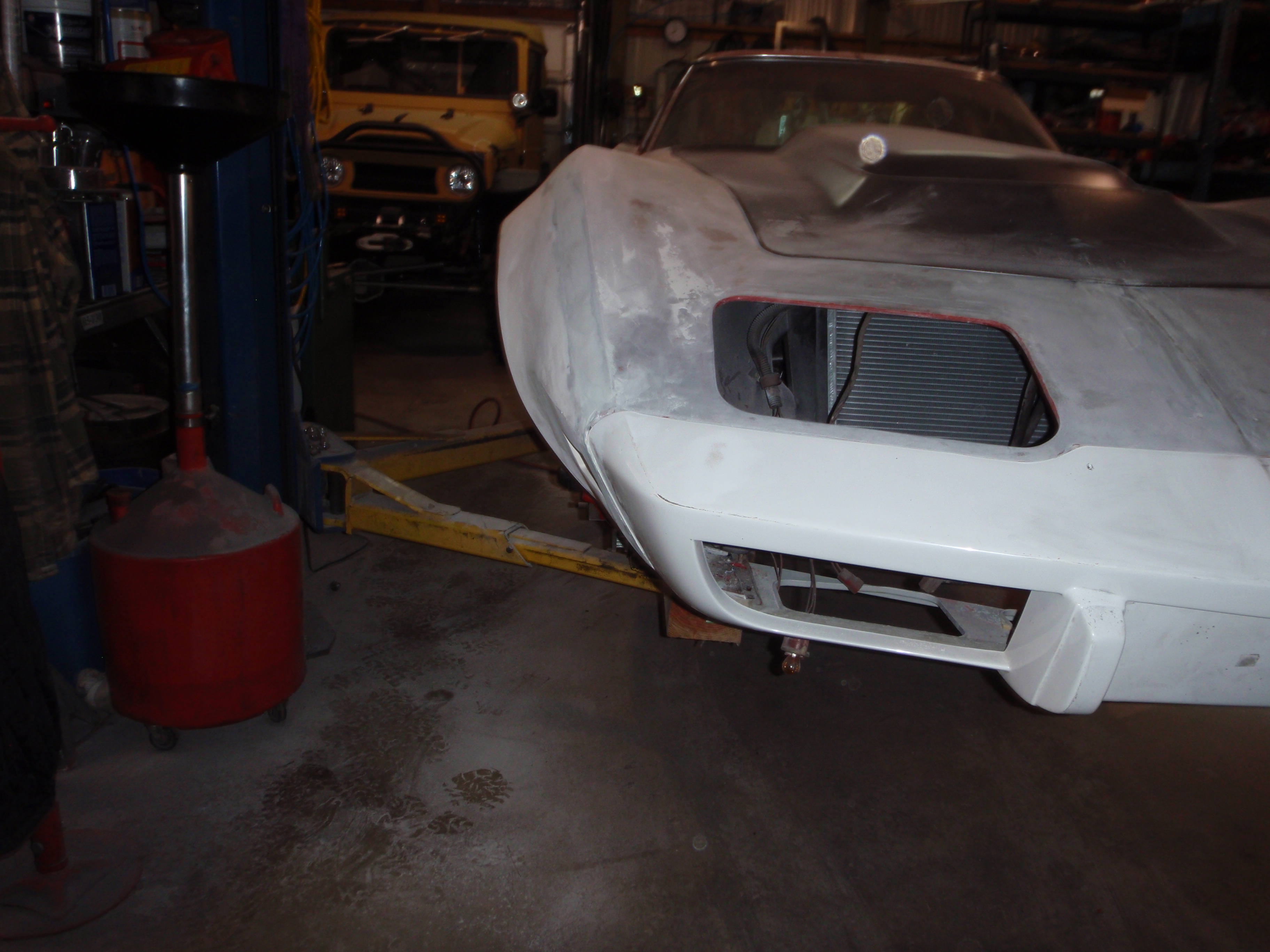
time to work on the nose - now that I have the hood, I can make all of this solid
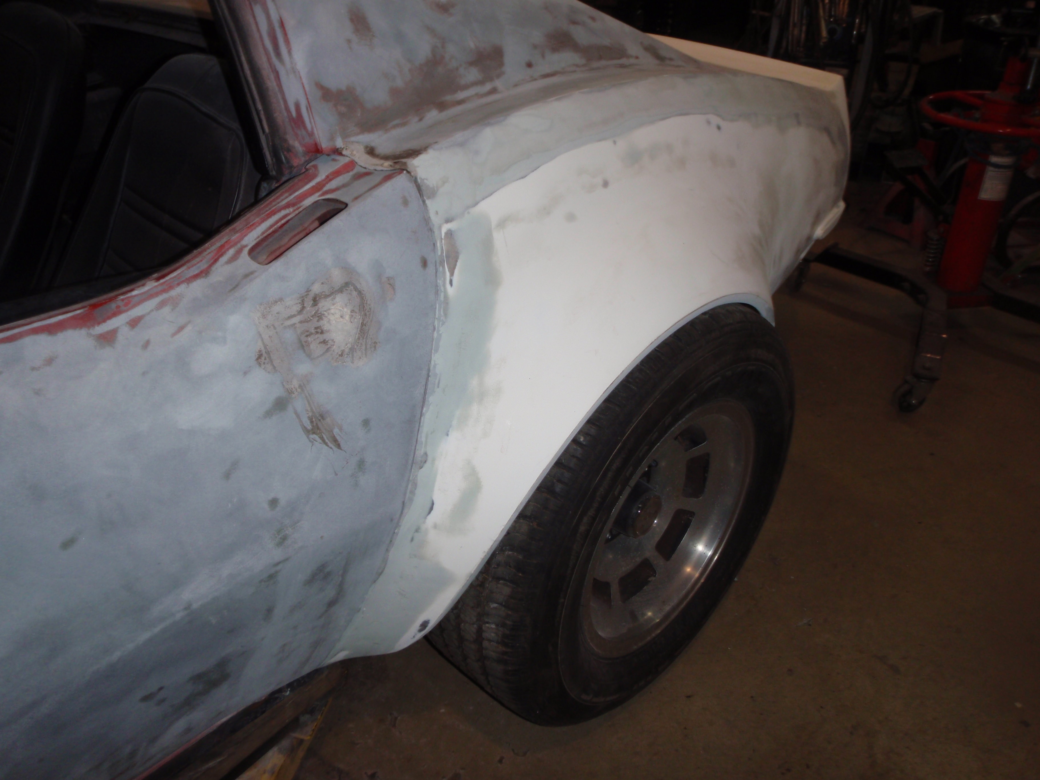
and spent some time getting the last of the paint off with aircraft remover (you can't see the aircraft so clearly it's worked)
verse 2
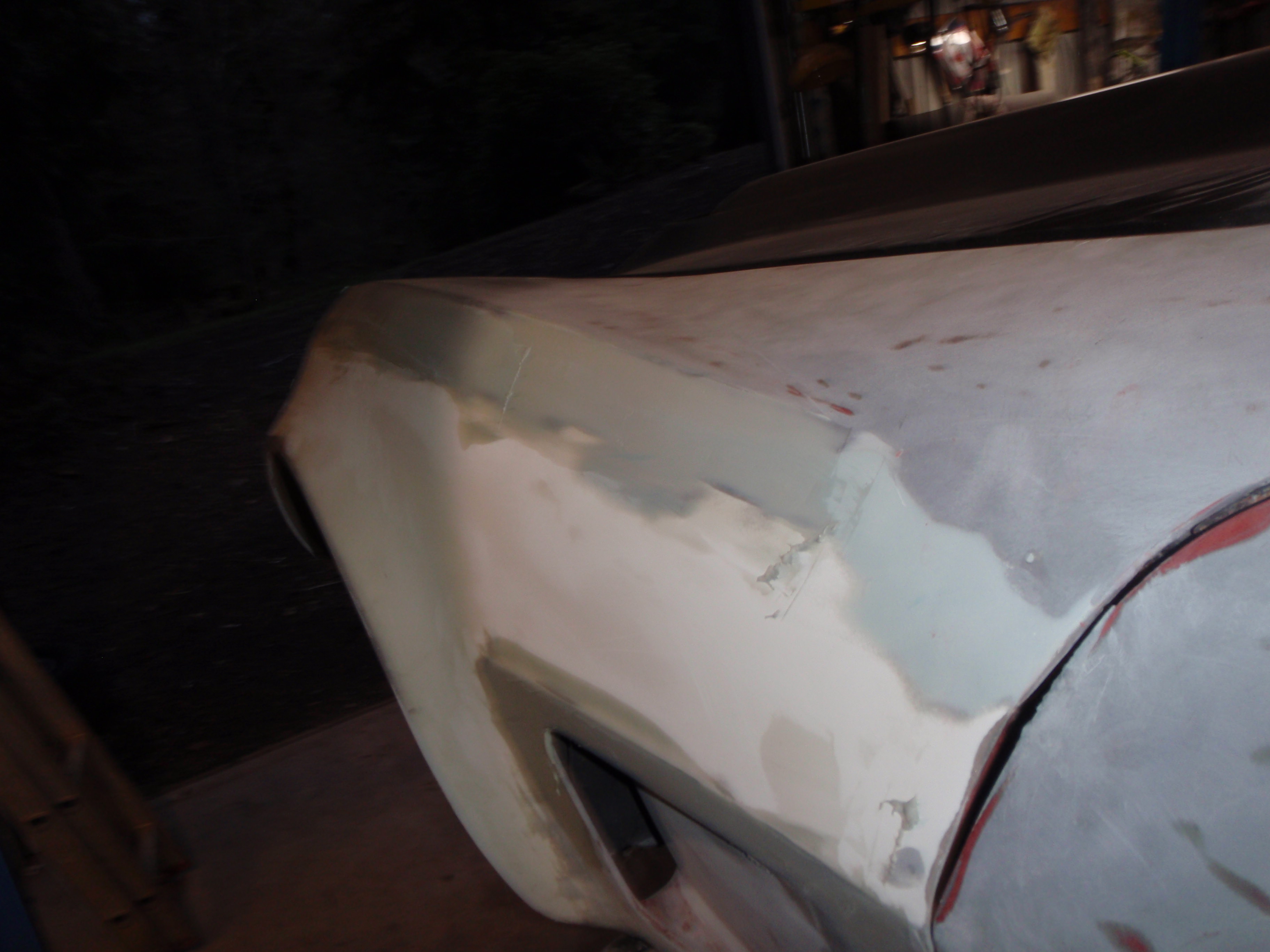
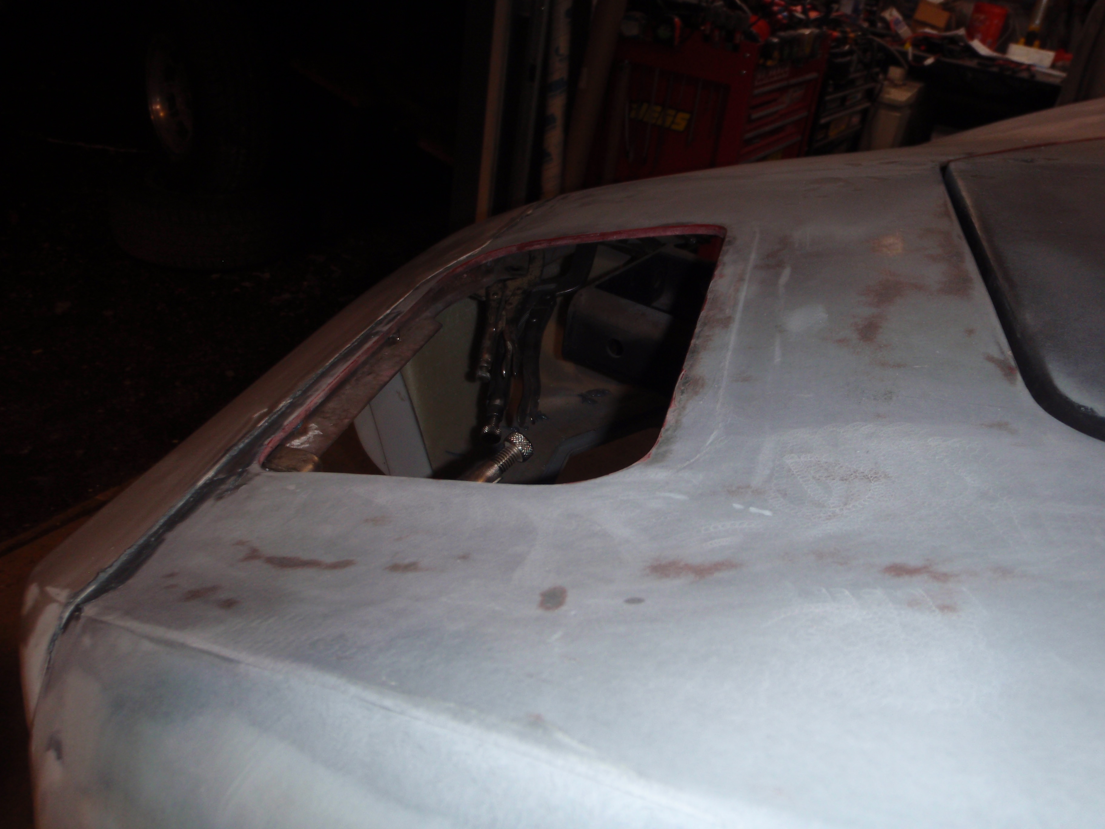
and the sail panels
things that puzzle - why would you only seal up the driver's side?
remove bolts
try fitting for real... ugh
better
if anyone is curious who made it
notsobetter - I solved this with heat.... pictures tomorrow.
oh you must be kidding me - need to drill out the support to 5/16
they suggest hood pins.... I have hood pins
schnazzy, no?
I'd love to move it closer to the windshield but the pins would go straight through the wiper pivot
wonder how much faster it would be if I turned them to flow with the wind?
onto other issues.... non-adherence of the fender
cut, glue, clamp fixeded
time to work on the nose - now that I have the hood, I can make all of this solid
and spent some time getting the last of the paint off with aircraft remover (you can't see the aircraft so clearly it's worked)
verse 2
and the sail panels
things that puzzle - why would you only seal up the driver's side?
03-27-2018, 12:31 AM
#143
Melting Slicks
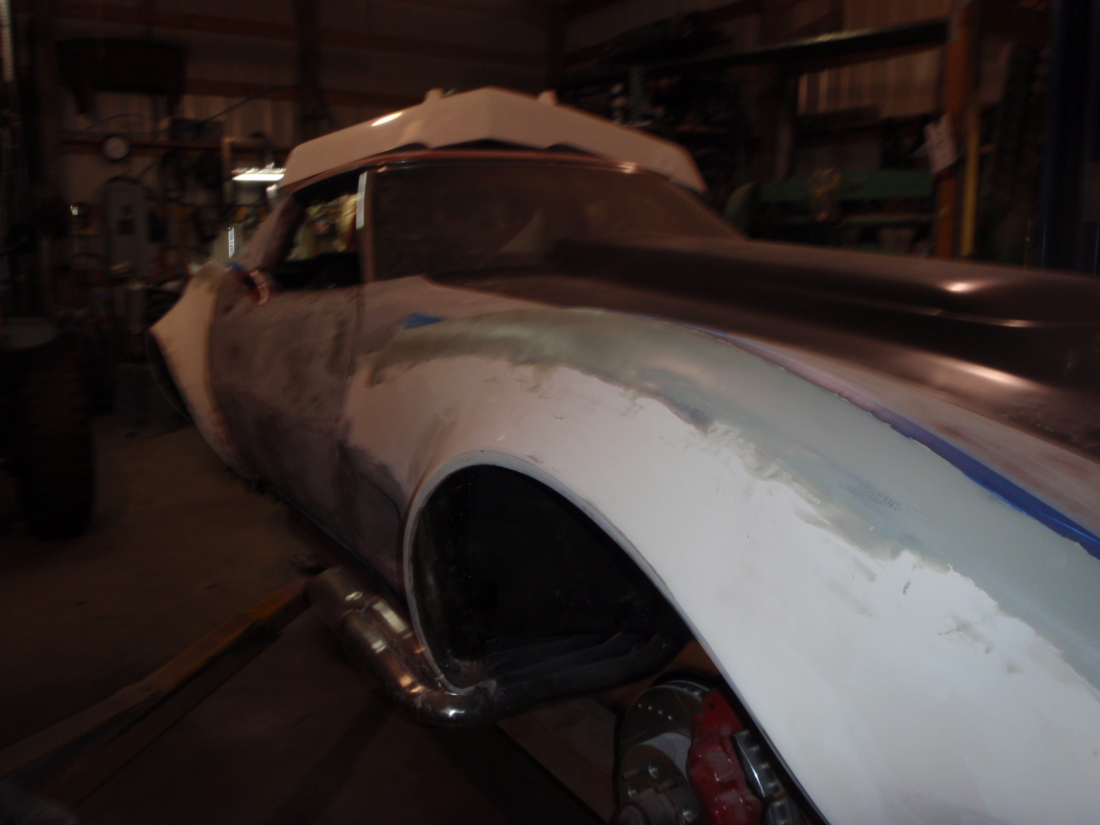
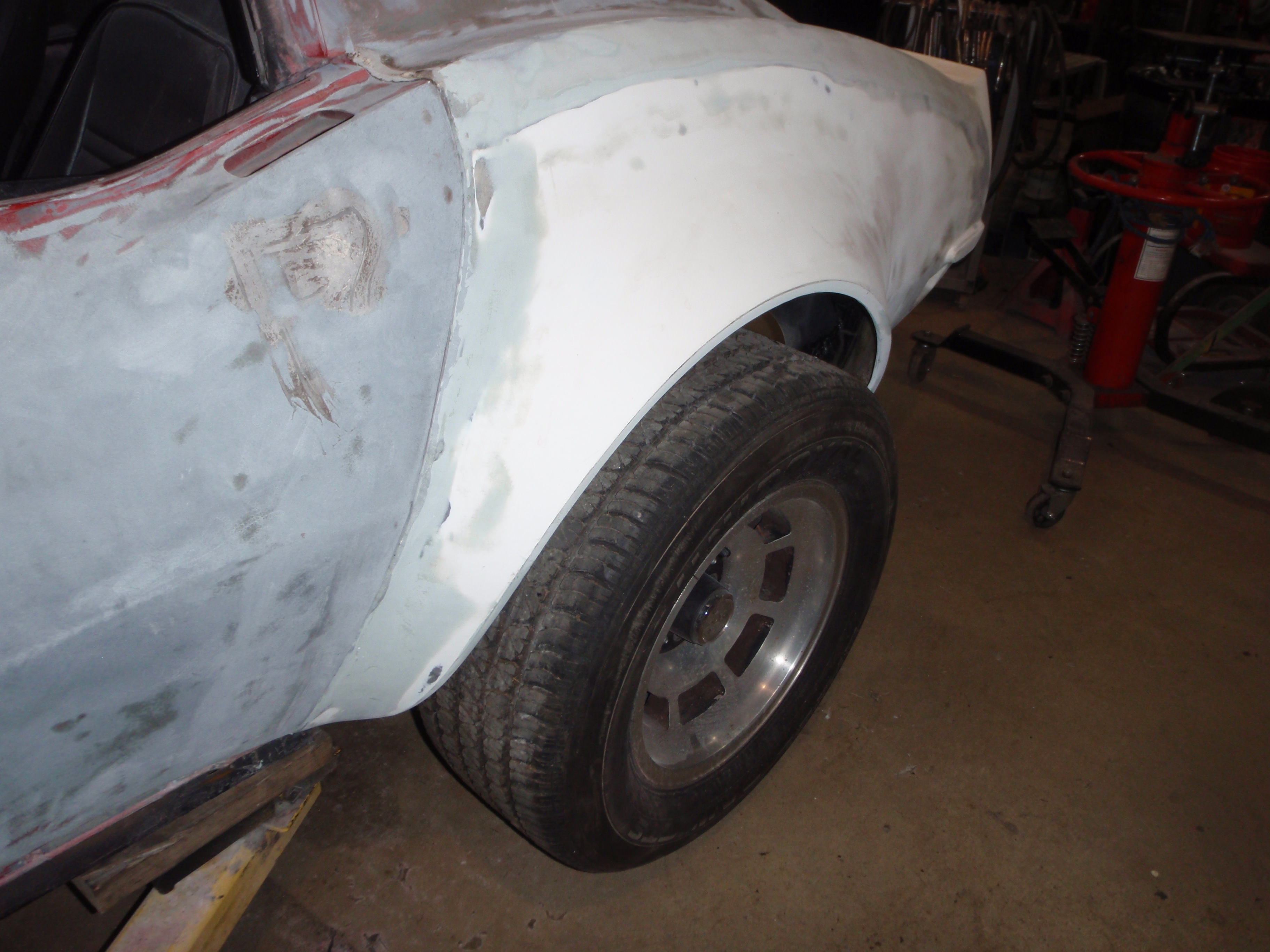
sanded a bit today
then spent quality time looking for door bolts
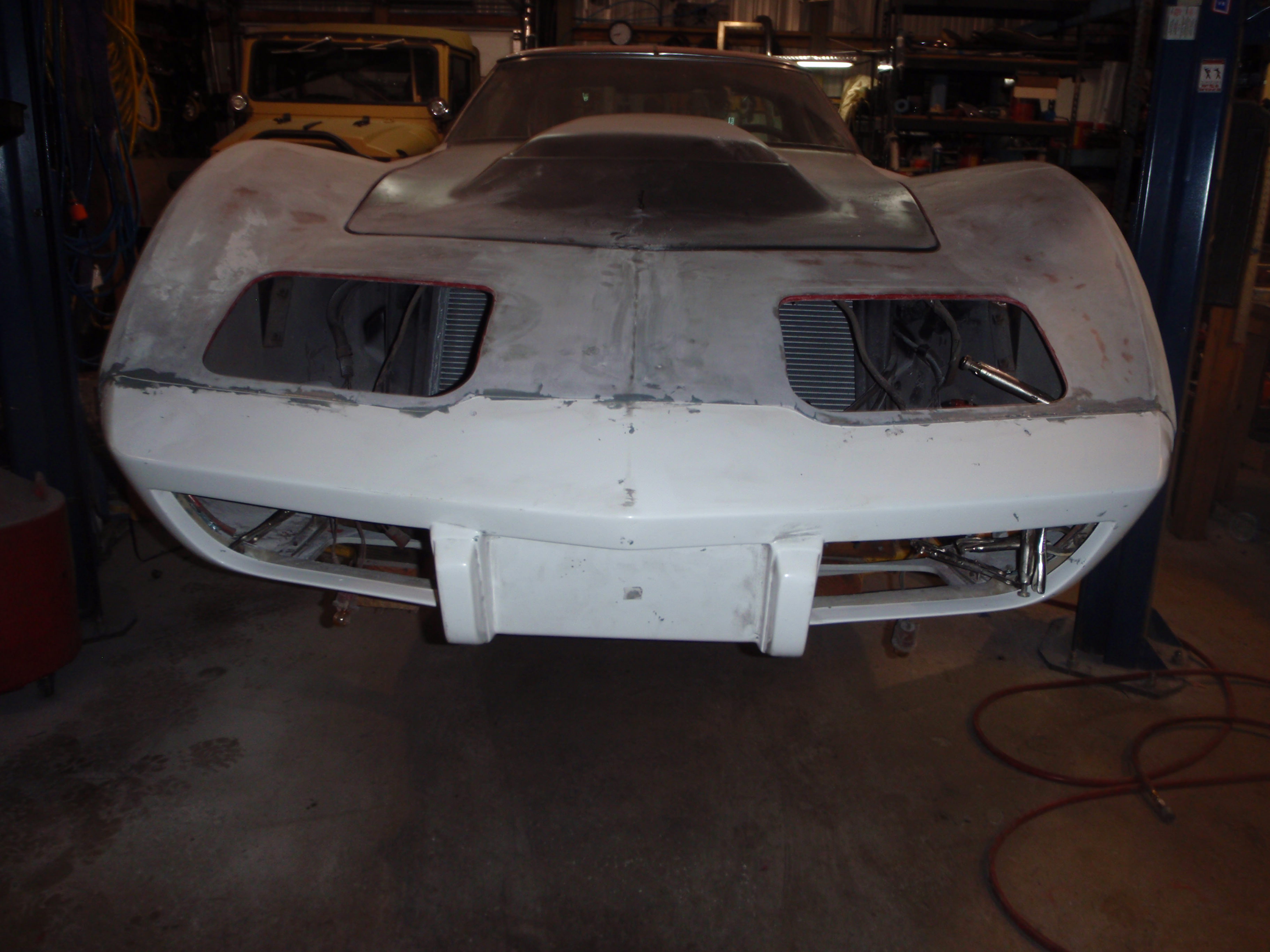
then worked a few minutes on the front.... I have the actuators coming so maybe I can get this buttoned up
then spent quality time looking for door bolts
then worked a few minutes on the front.... I have the actuators coming so maybe I can get this buttoned up
03-28-2018, 12:48 AM
#144
Melting Slicks
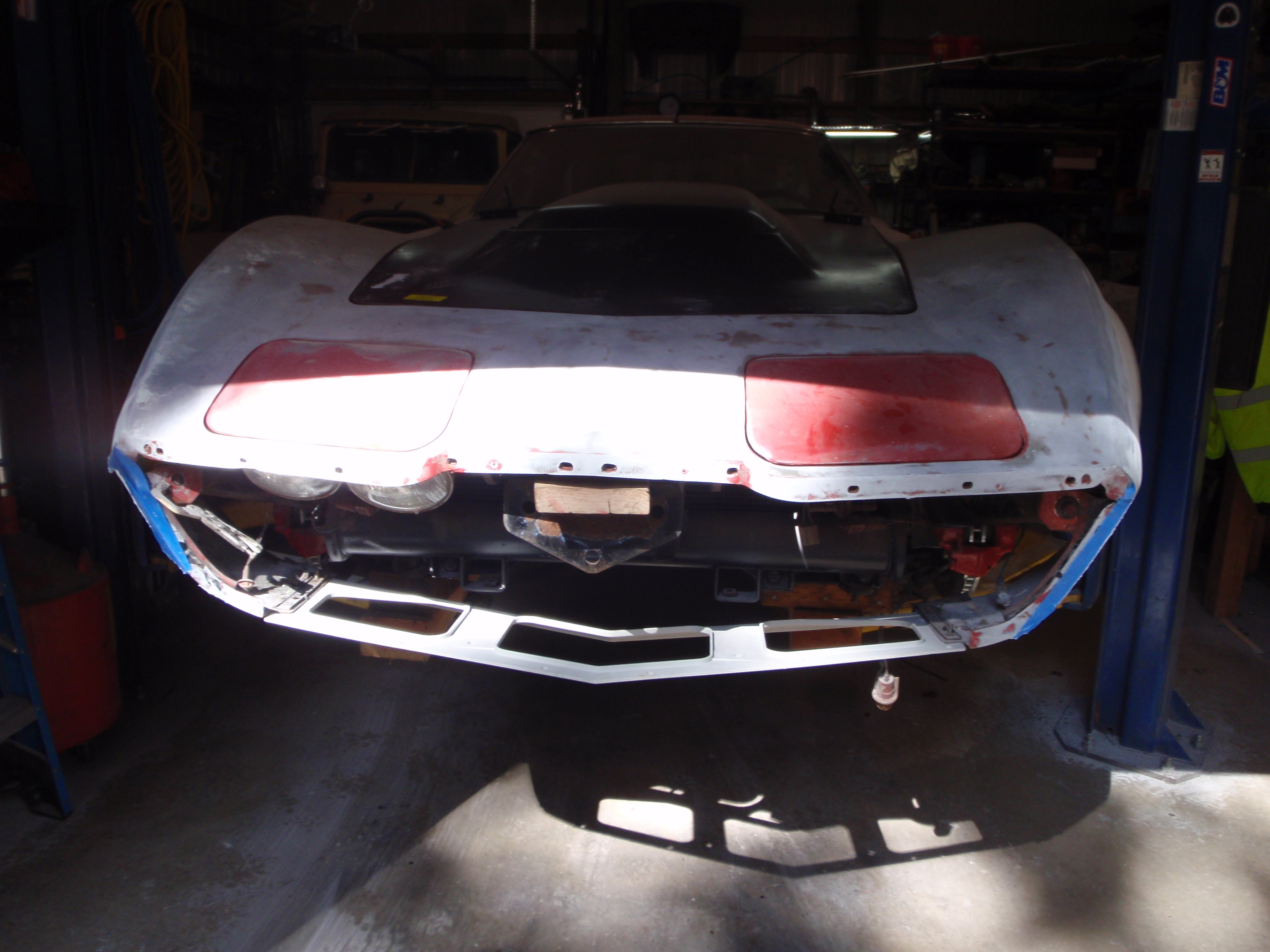
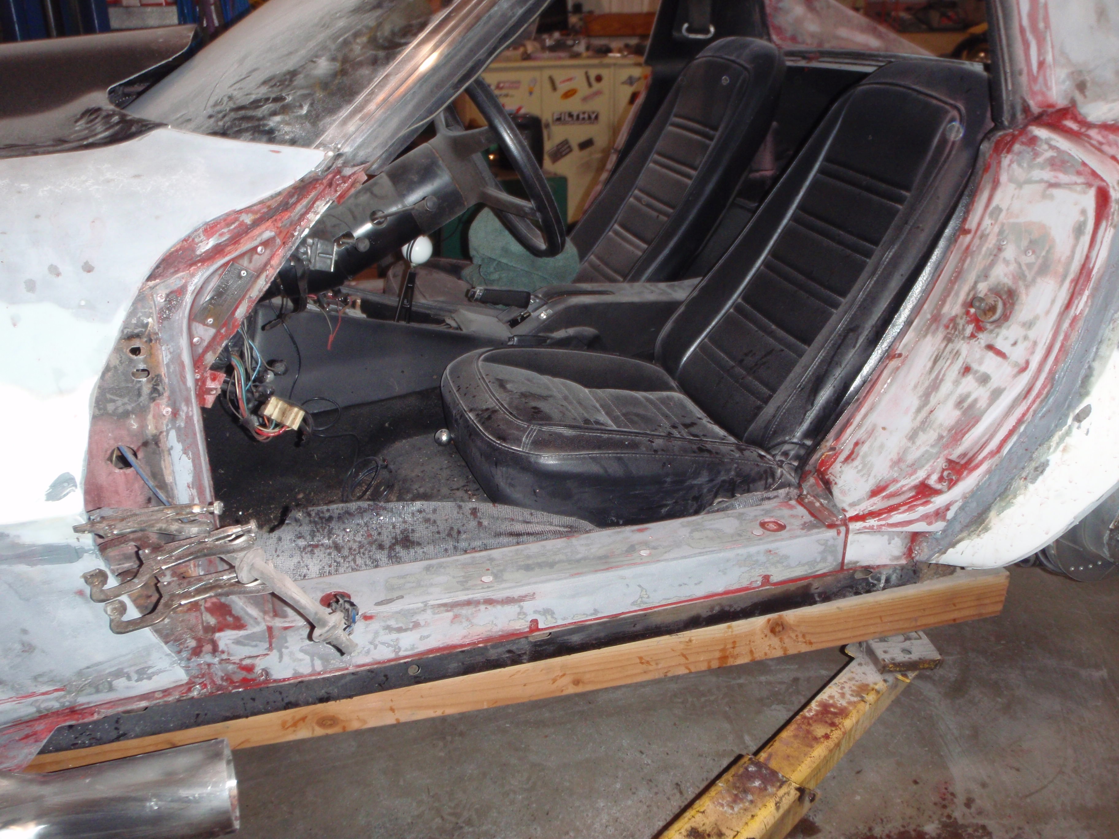
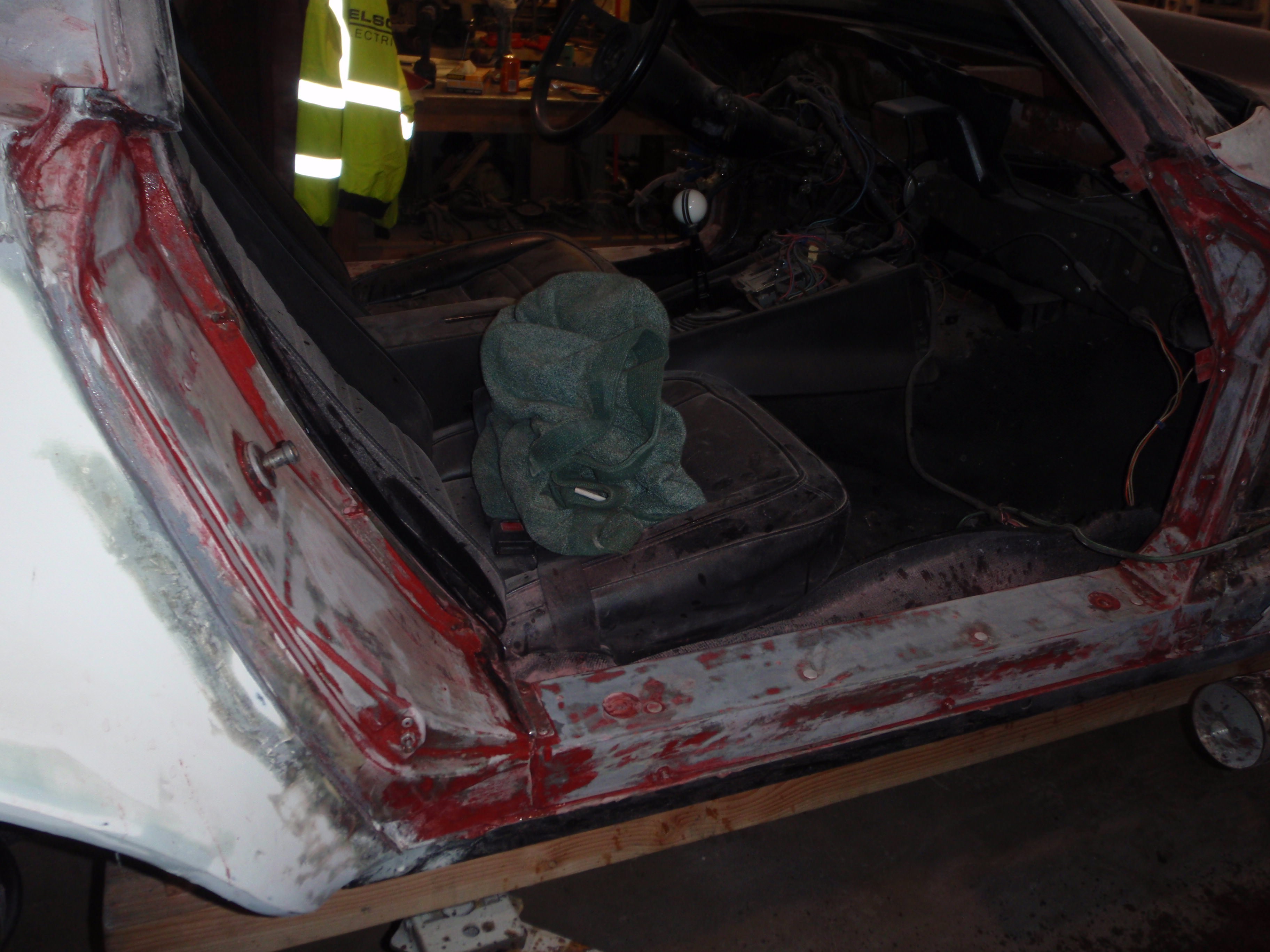
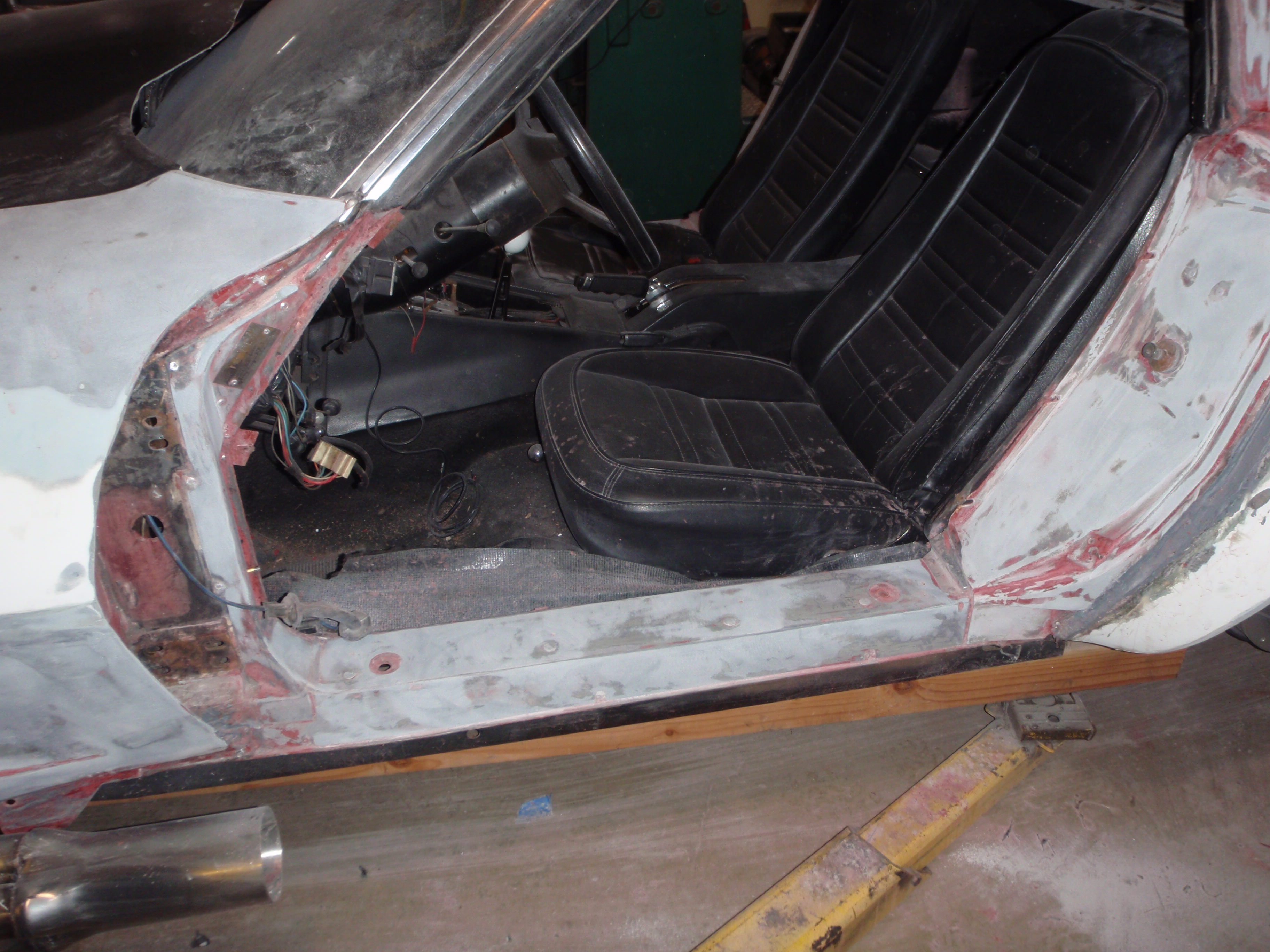
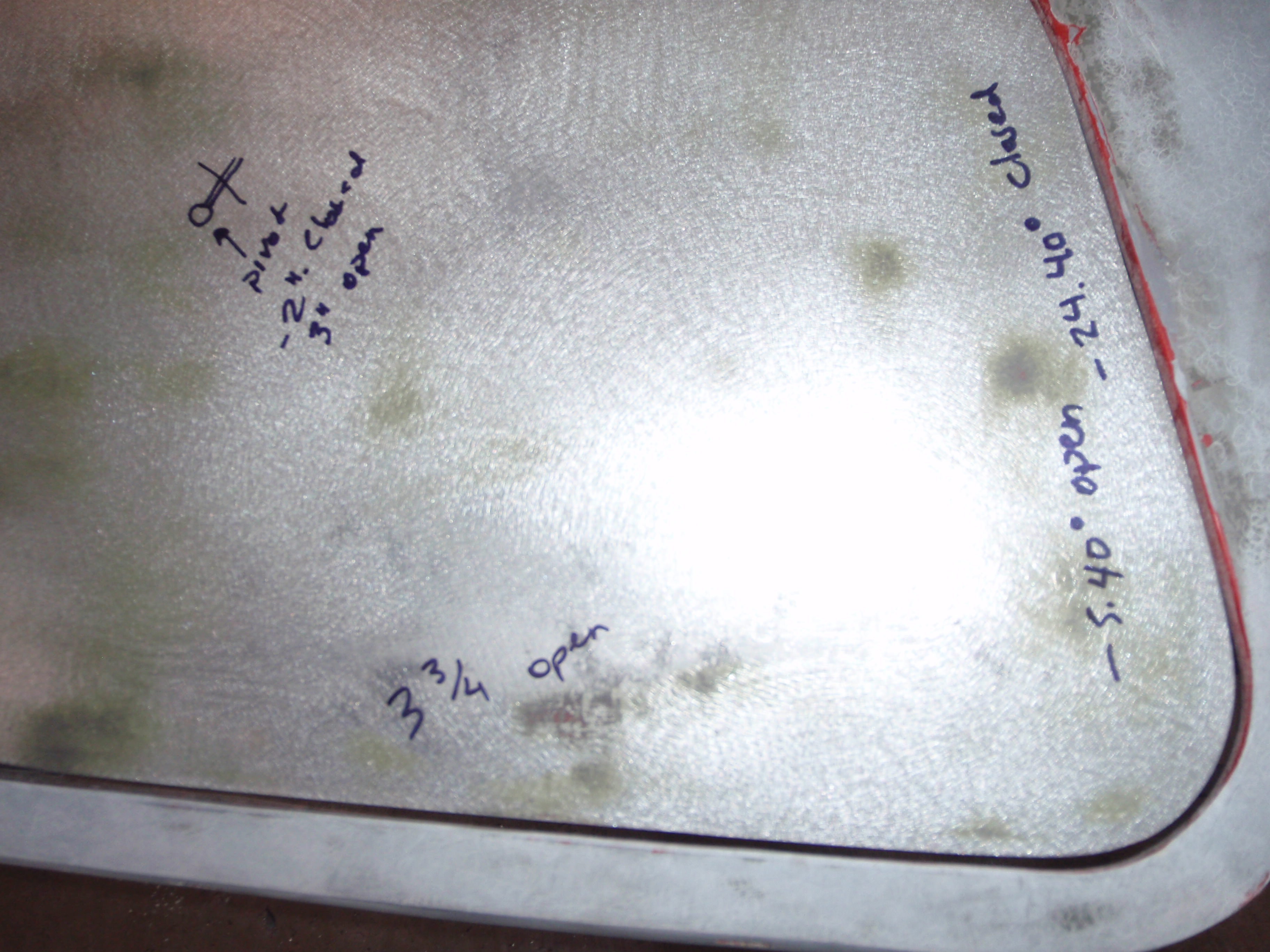
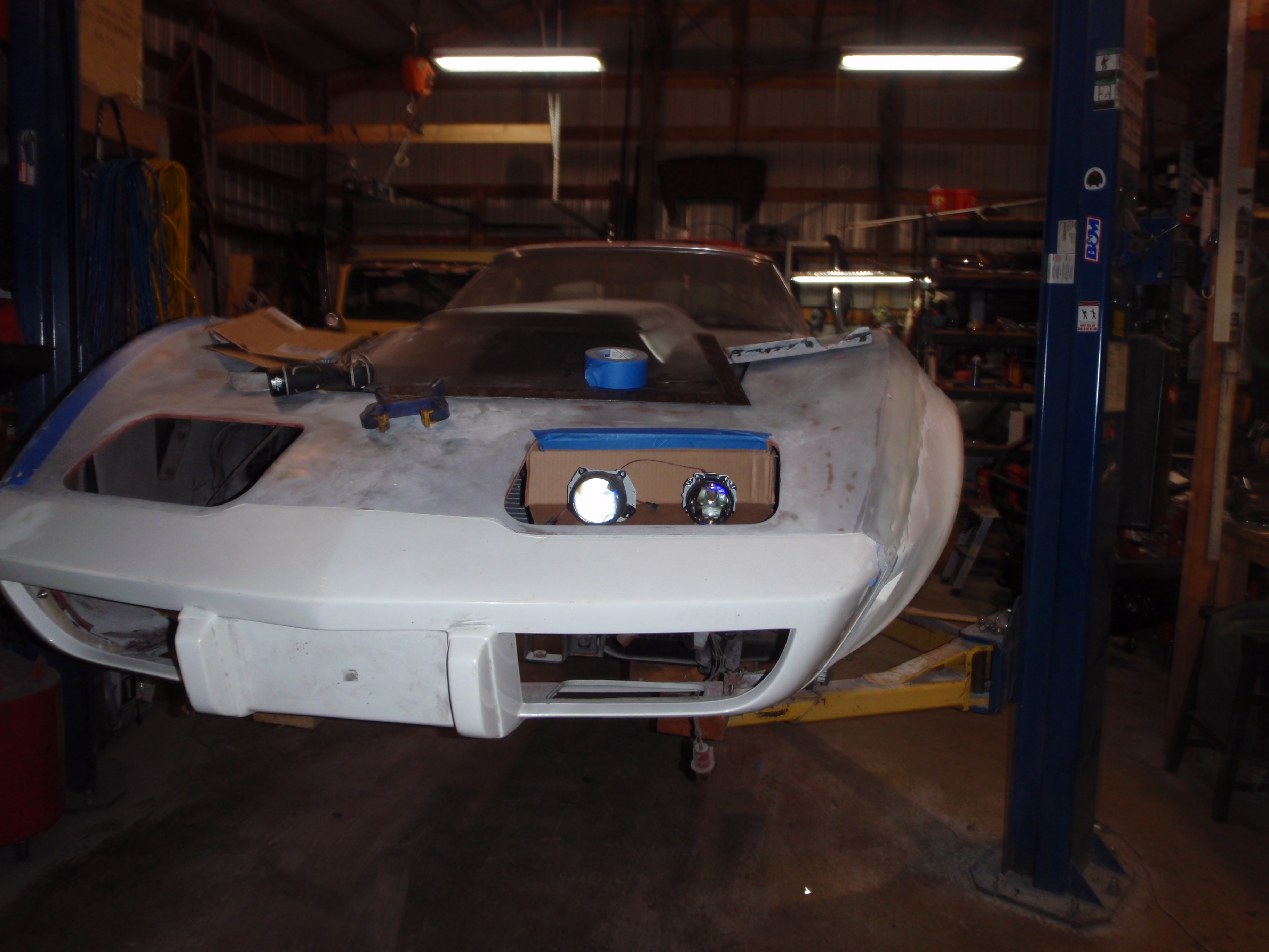
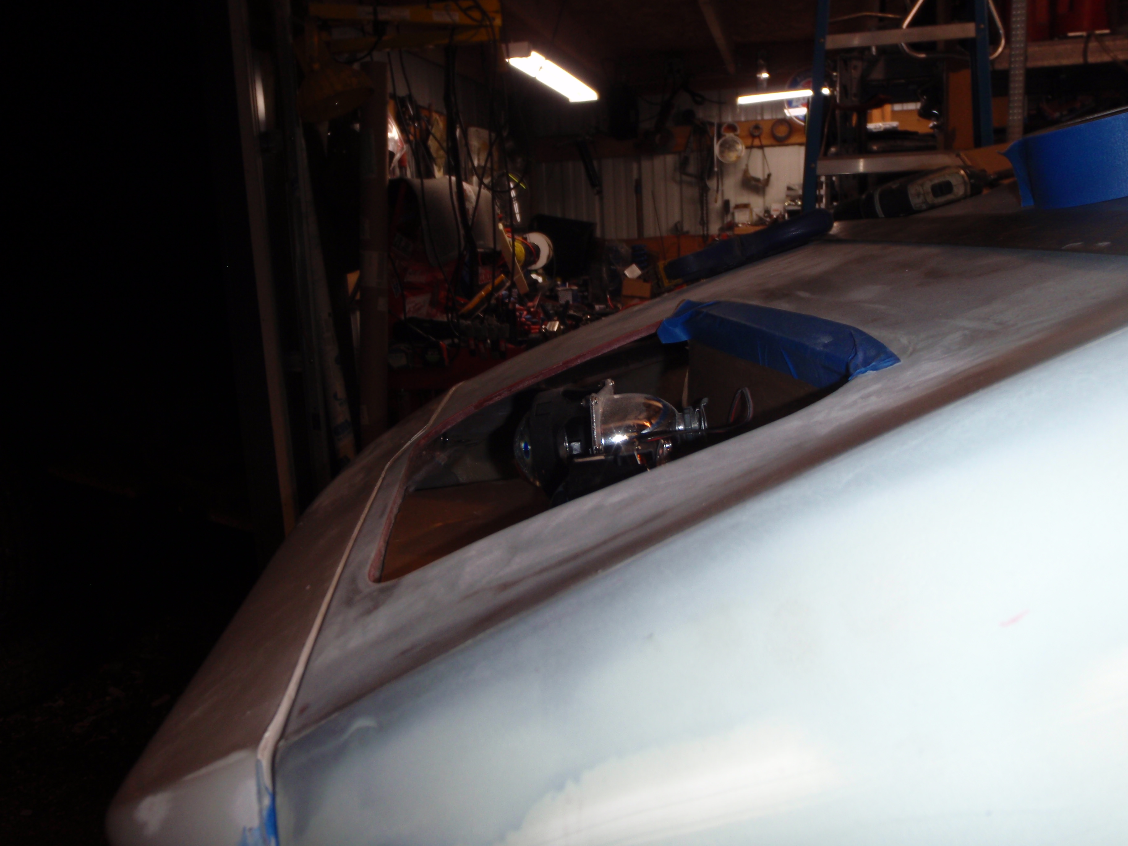
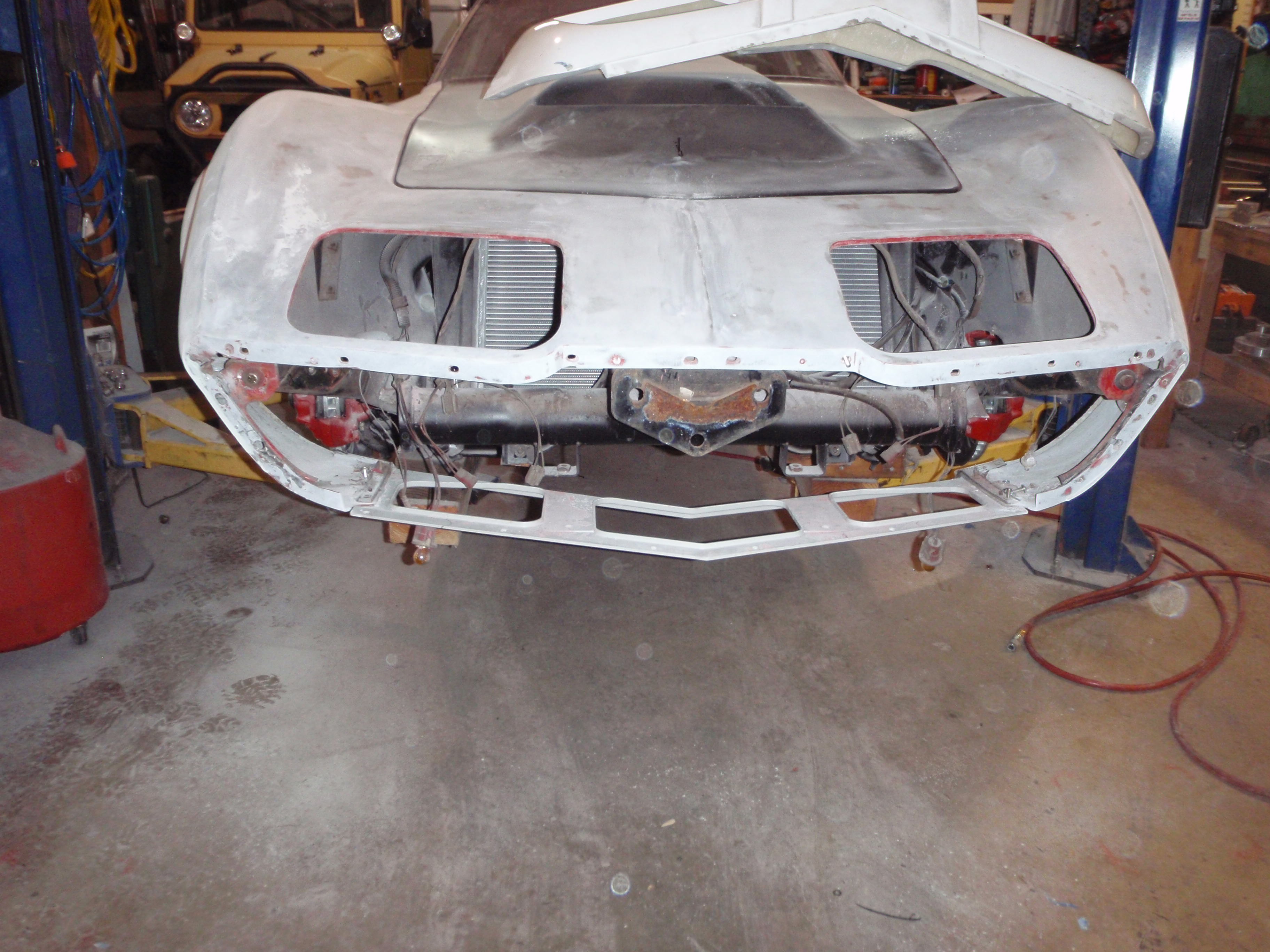
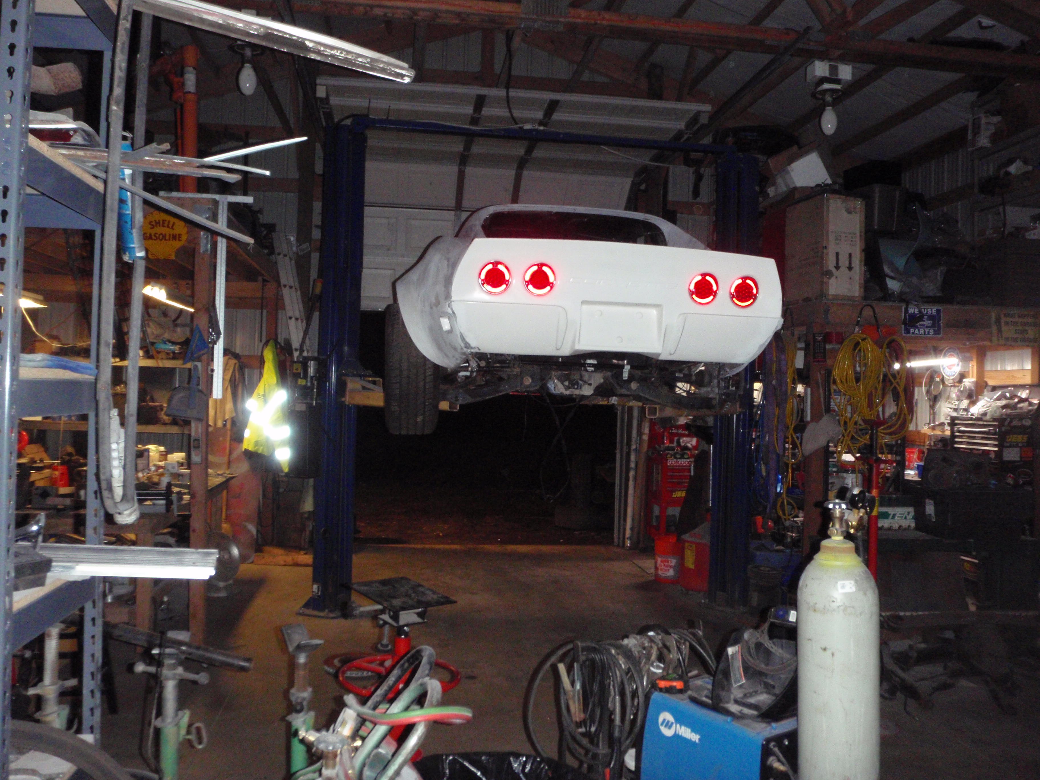
more steps... time to figure out the angles and pull the buckets out
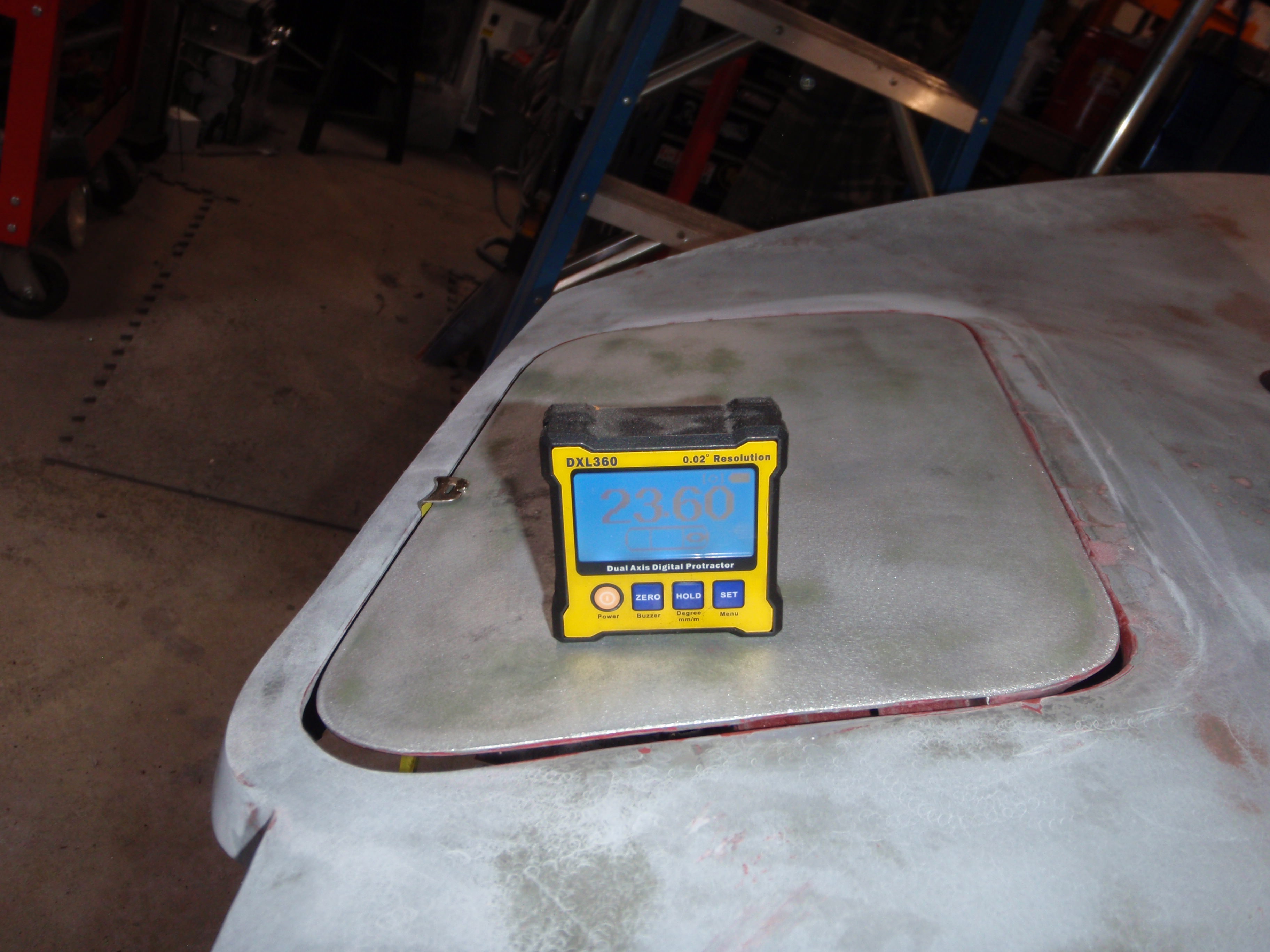
next day or so I'll be using those measurements to put the projection lights in
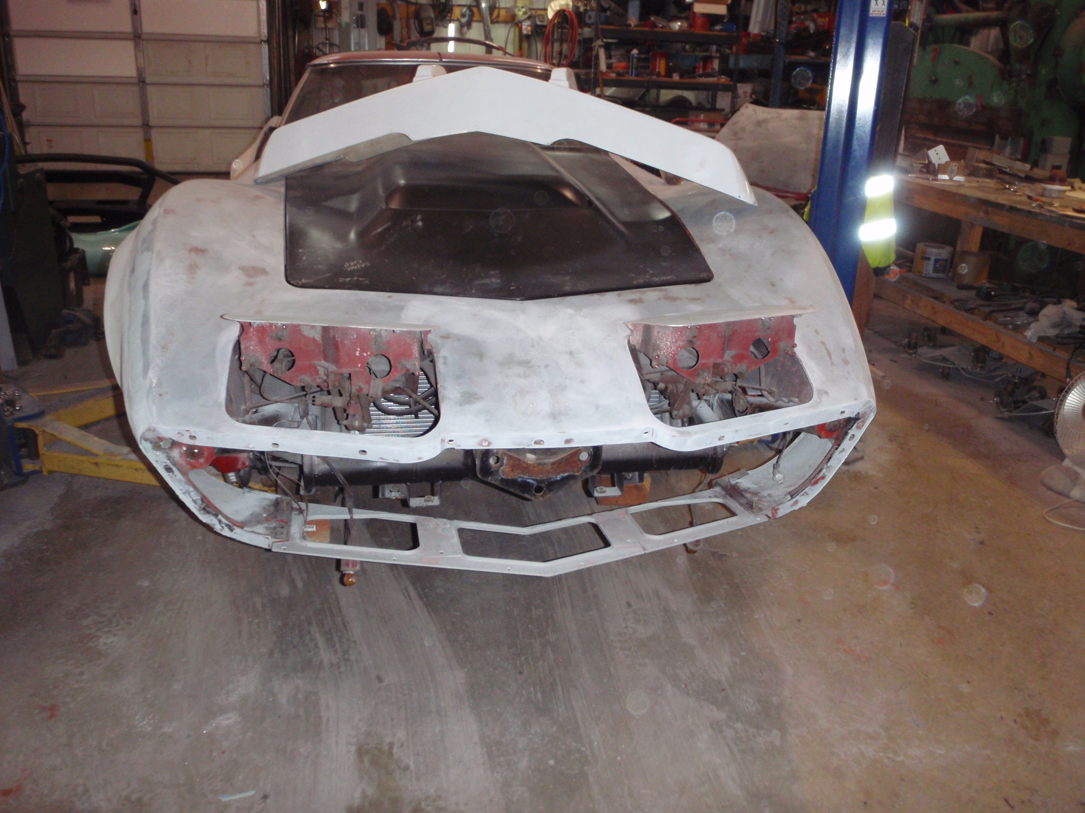
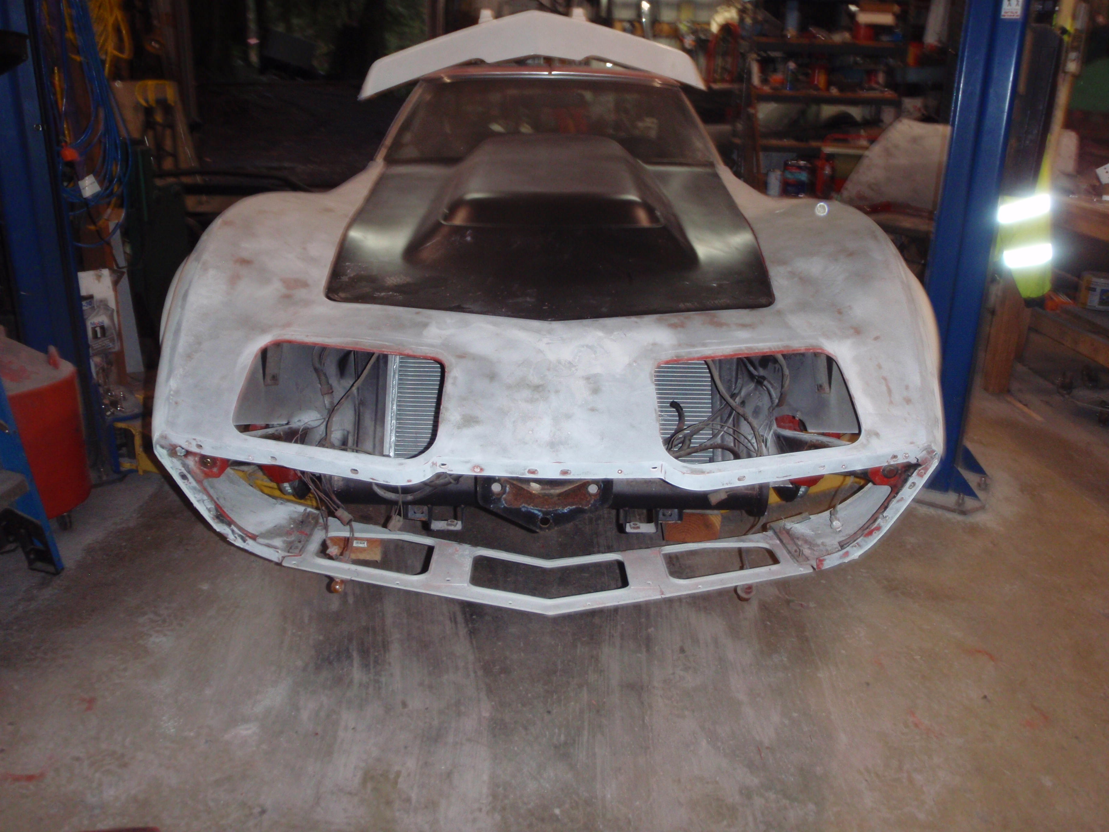
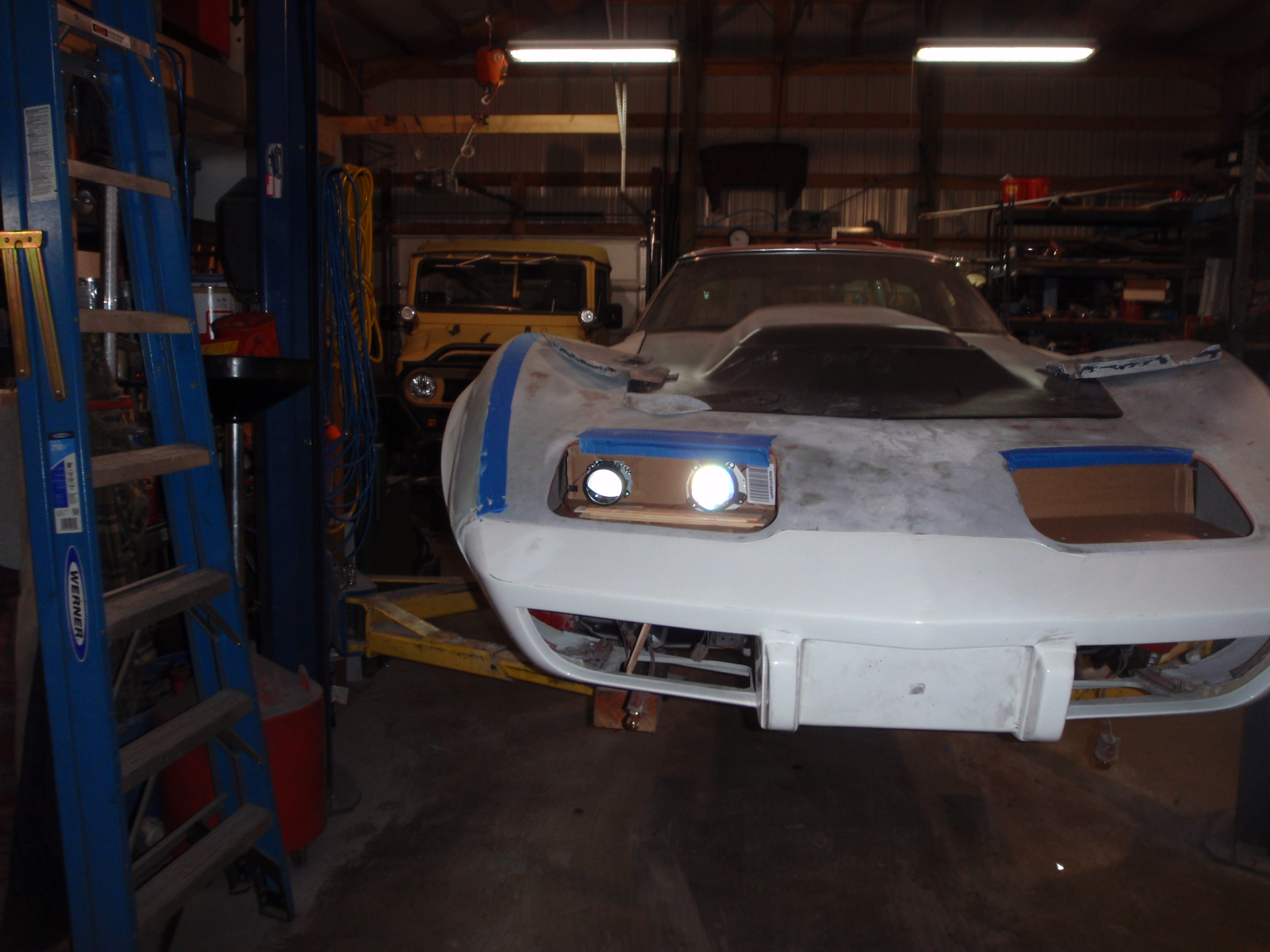
now big, gaping grill hole
I know it seems soon to buy these, but I need to do whatever bracing - that means hole drilling, something I hate doing in new paint
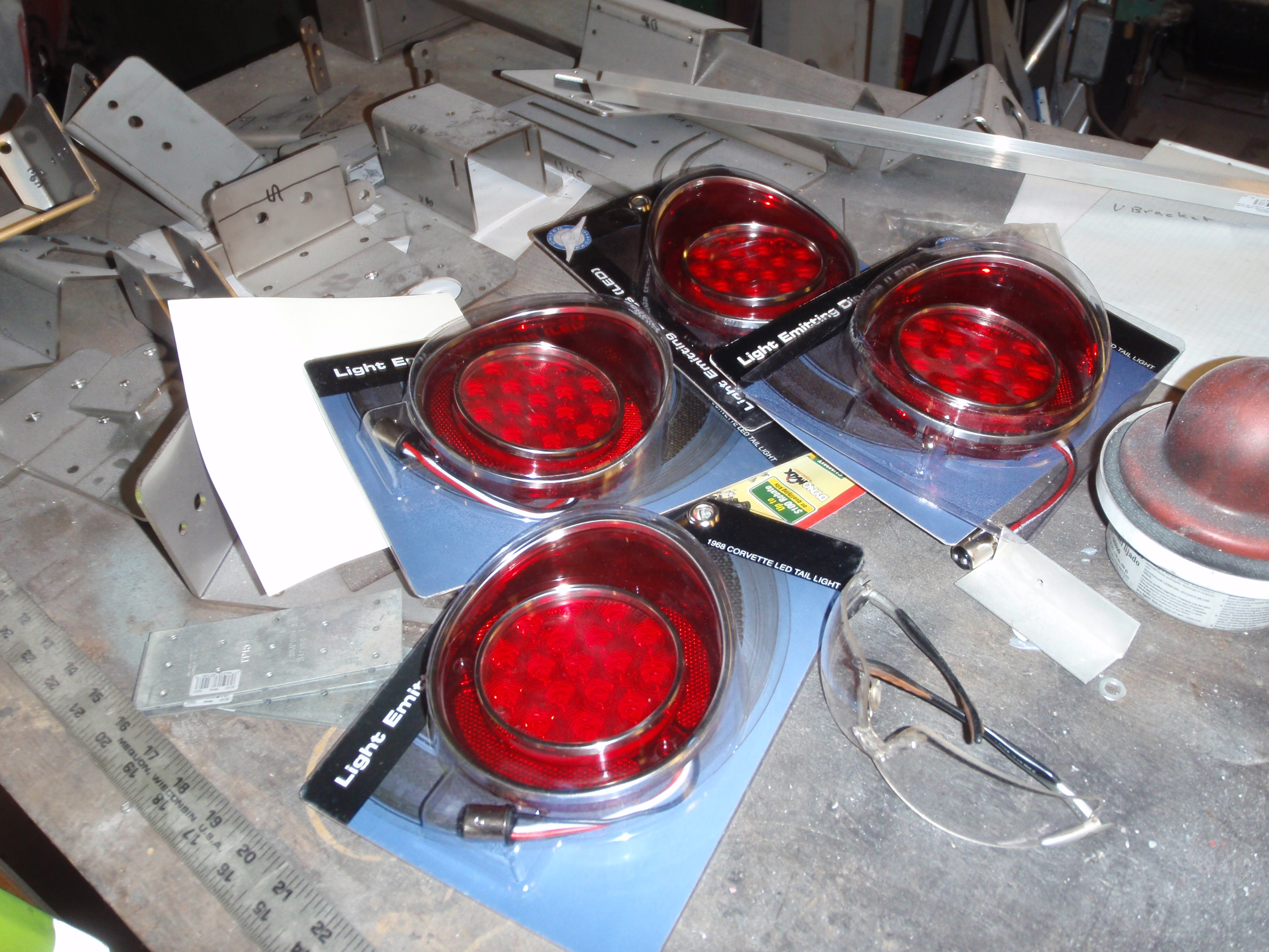
cringe - I suspect these will be the Waterloo of the lights - because it is exposed to the elements
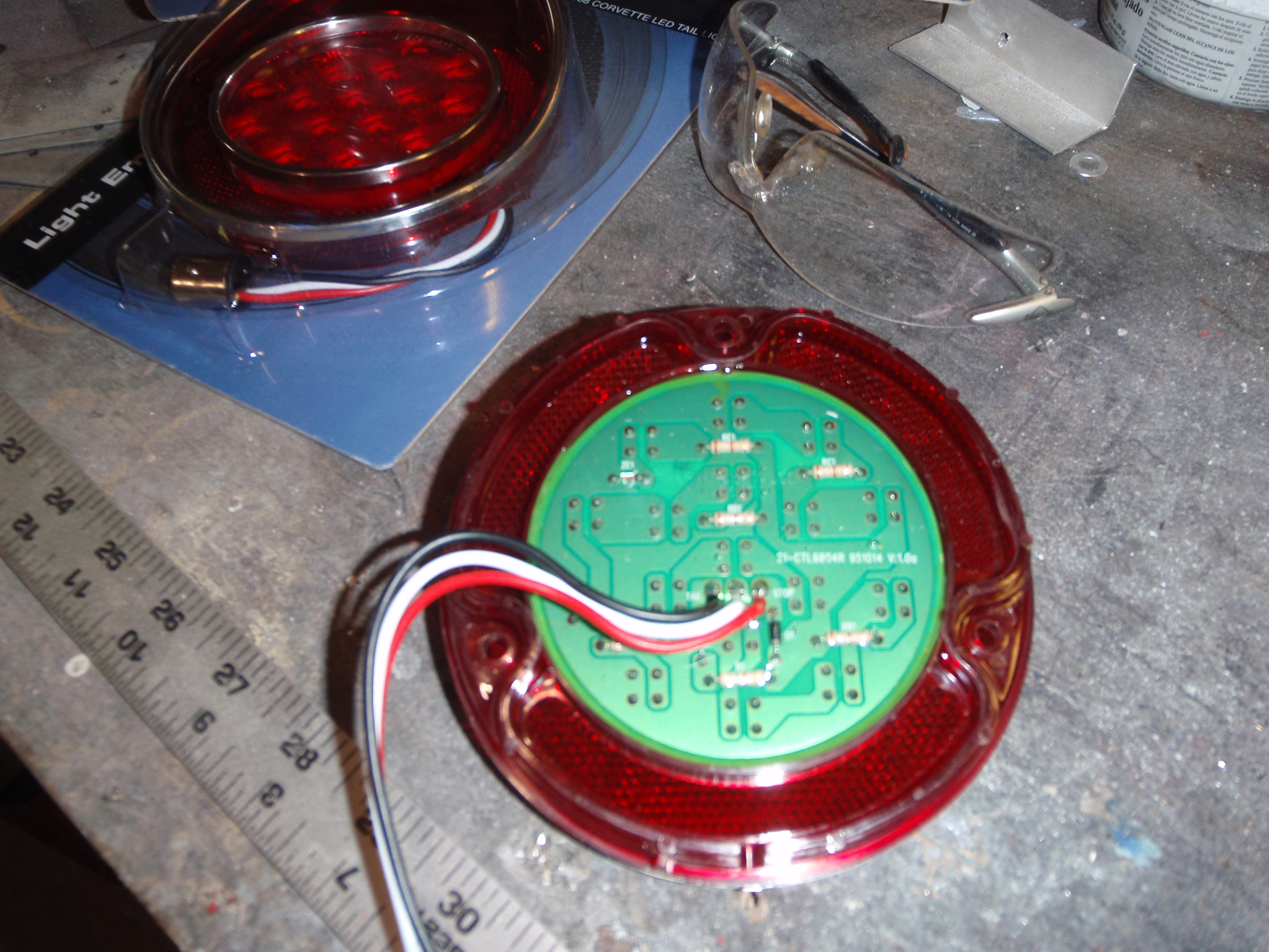
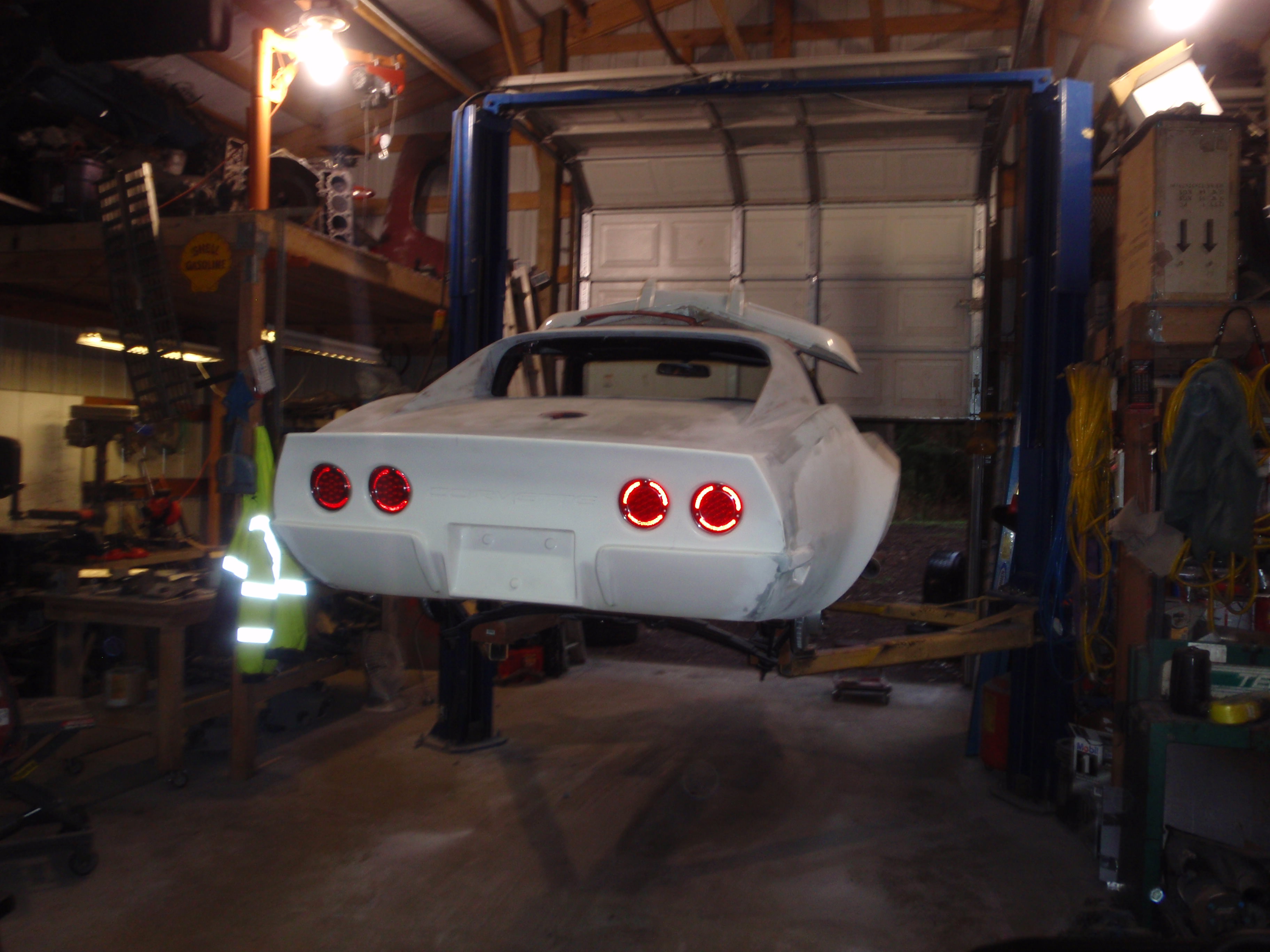
I like, a lot
I did try to get it off without damage, but alas, no
I didn't damage the door, though, and that's a win
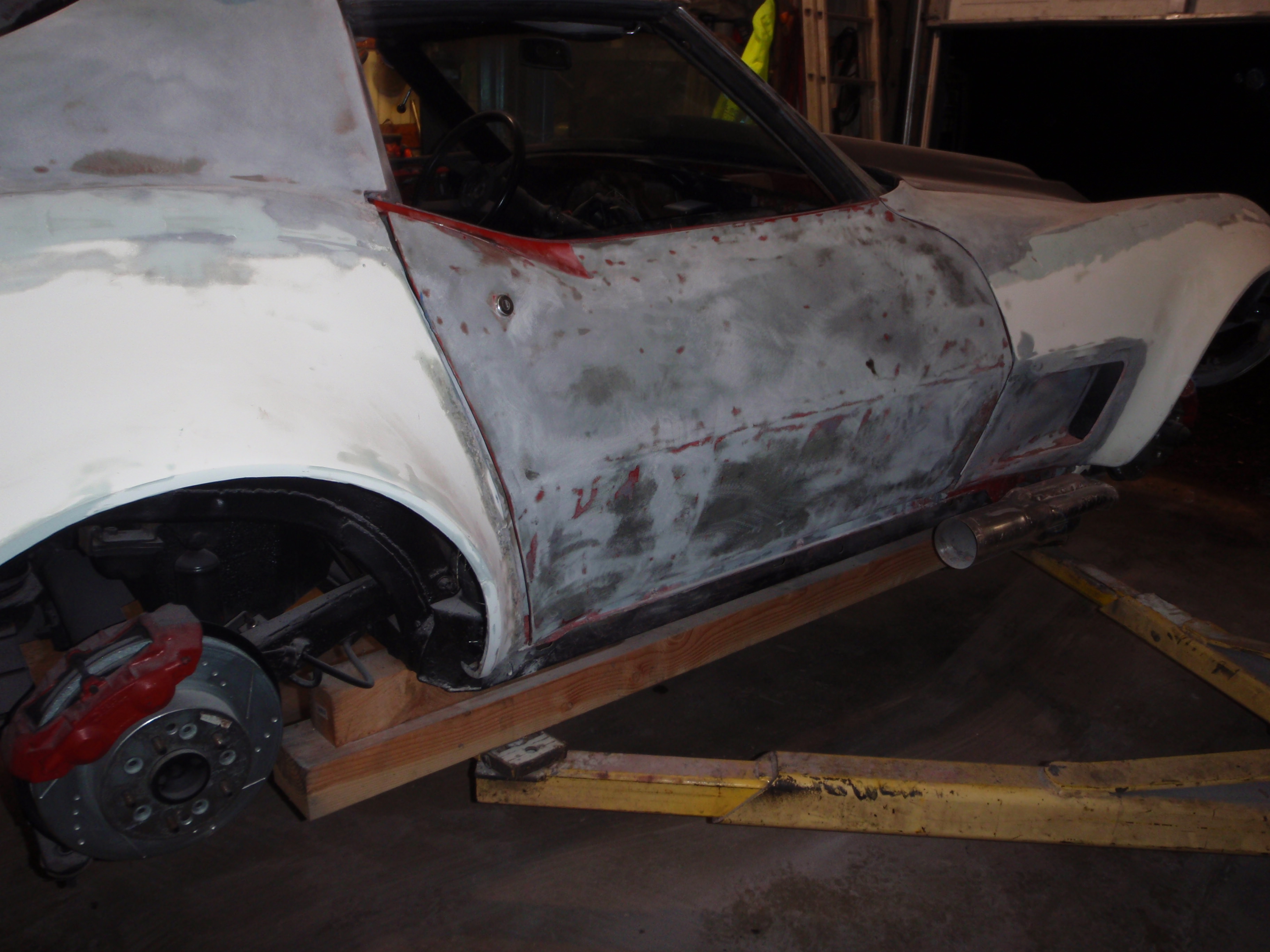
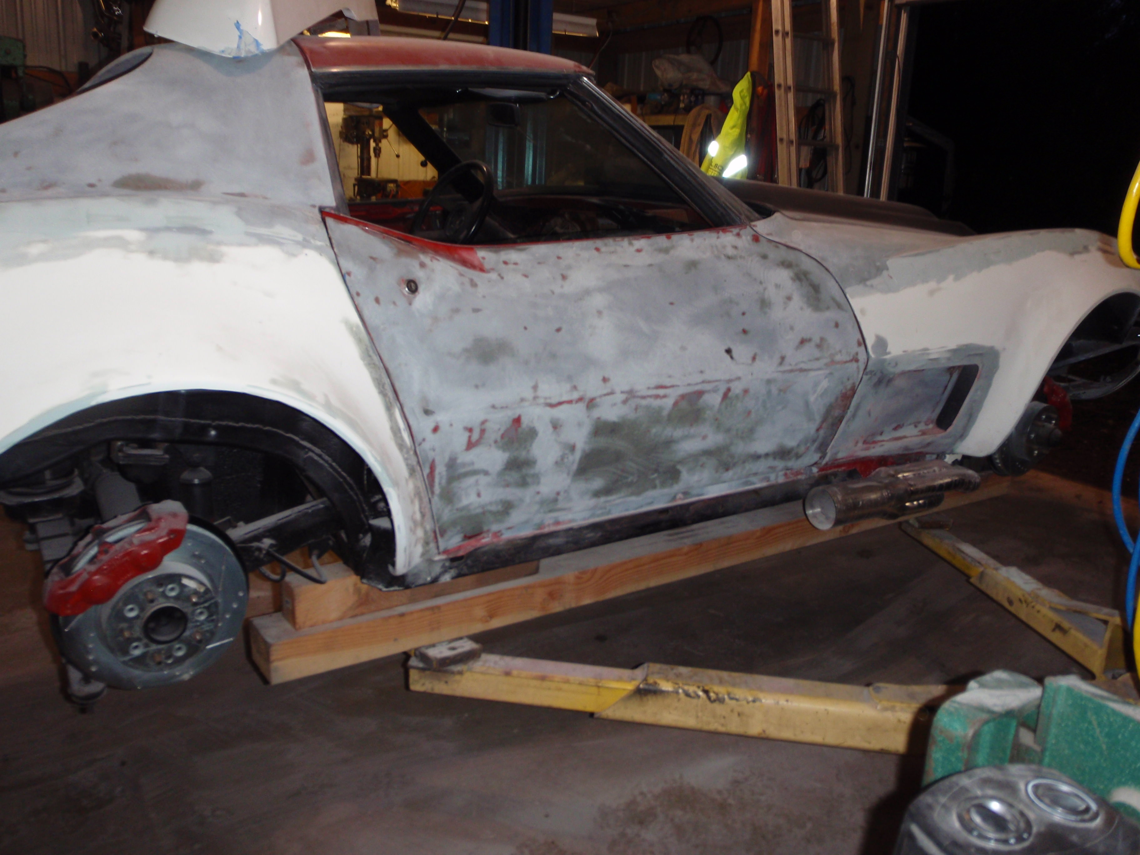
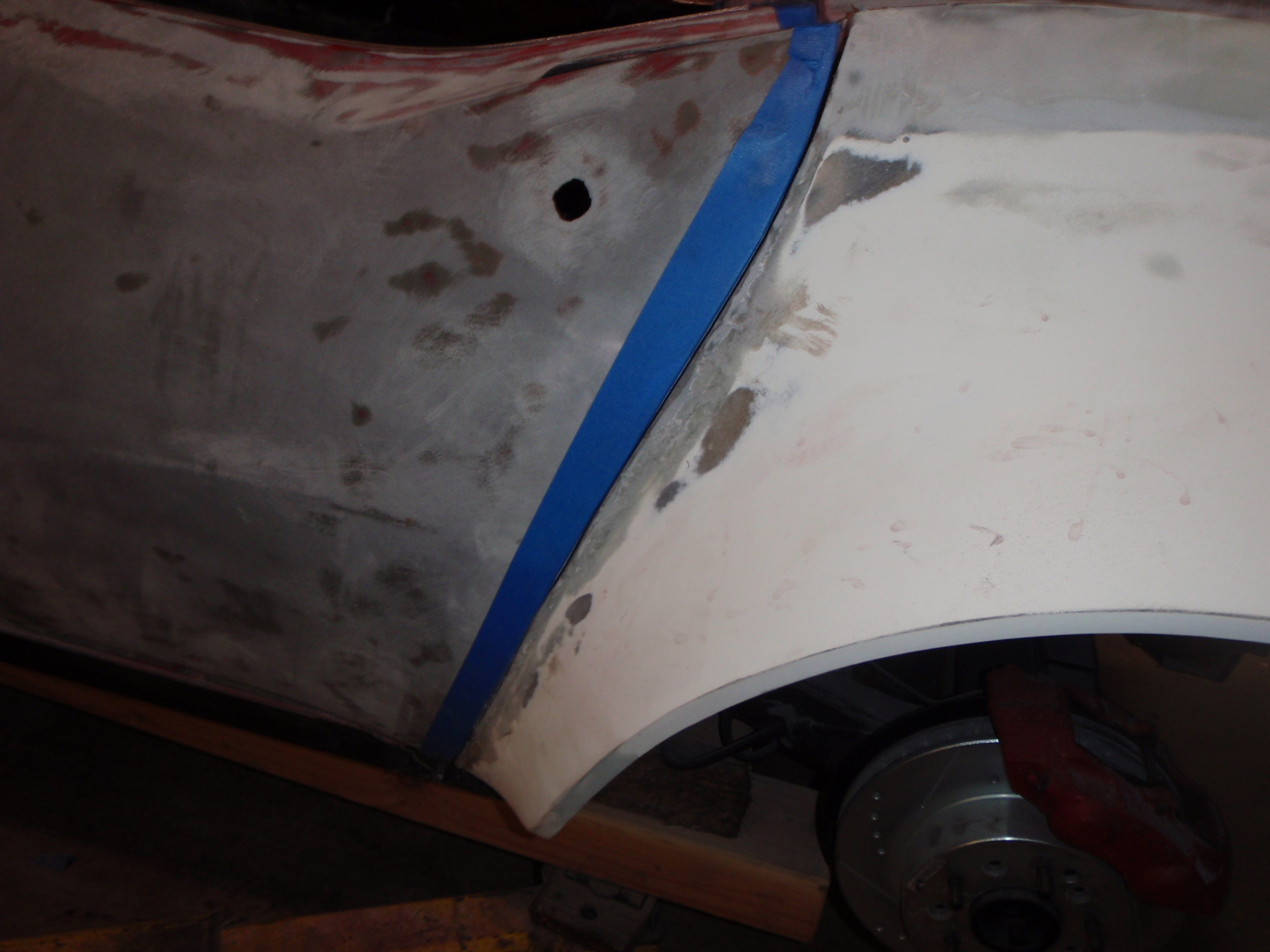
put the doors back on to re-set the gaps
I got pretty close, a bit of tuning then the doors can come back off to finish stripping and do whatever the decision will be about widening this area
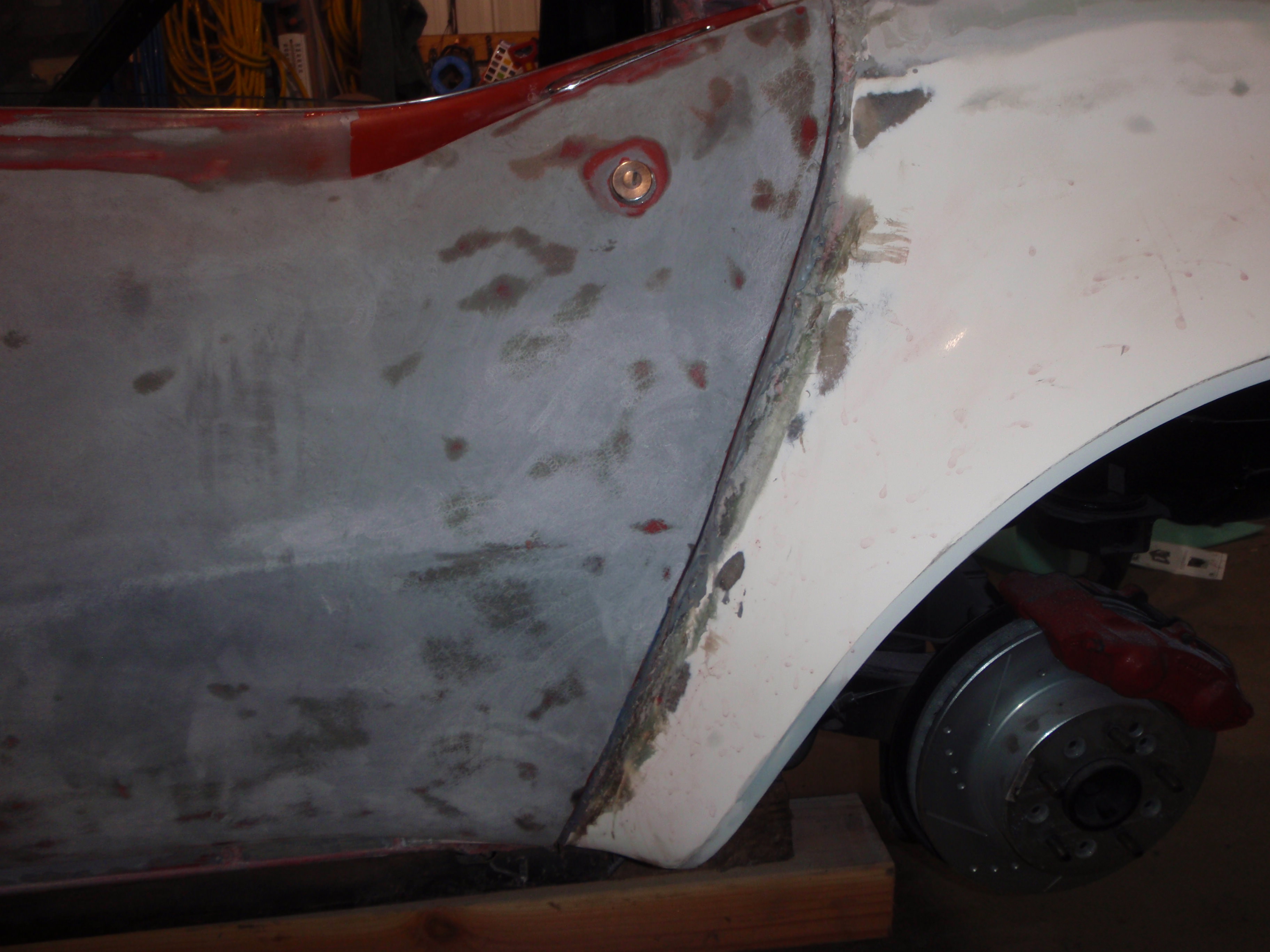
the gap is gone
I ran out of time, so it's not really fully on and lined up
next day or so I'll be using those measurements to put the projection lights in
now big, gaping grill hole
I know it seems soon to buy these, but I need to do whatever bracing - that means hole drilling, something I hate doing in new paint
cringe - I suspect these will be the Waterloo of the lights - because it is exposed to the elements
I like, a lot
I did try to get it off without damage, but alas, no
I didn't damage the door, though, and that's a win
put the doors back on to re-set the gaps
I got pretty close, a bit of tuning then the doors can come back off to finish stripping and do whatever the decision will be about widening this area
the gap is gone
I ran out of time, so it's not really fully on and lined up
03-29-2018, 12:05 AM
#145
Melting Slicks
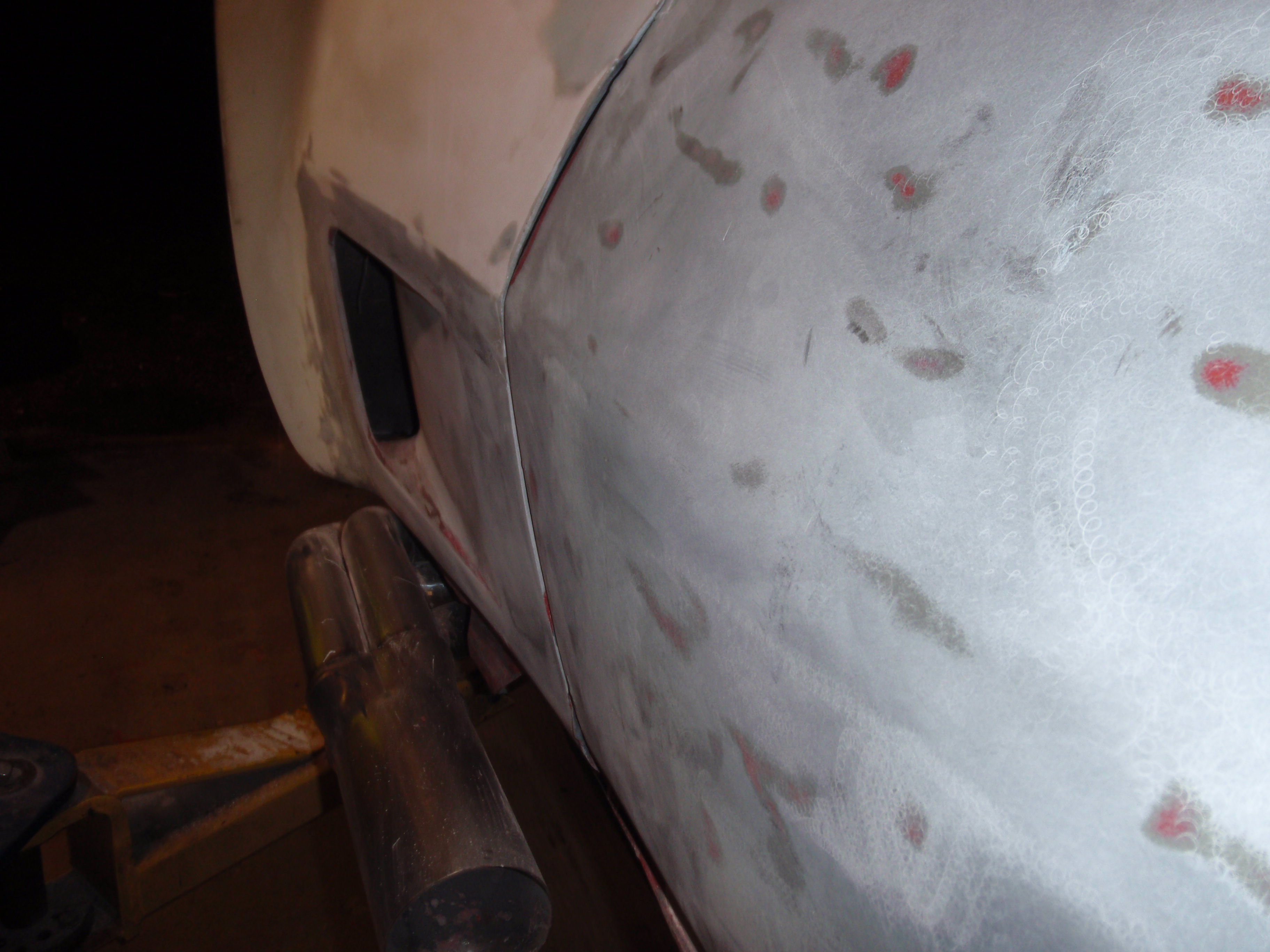
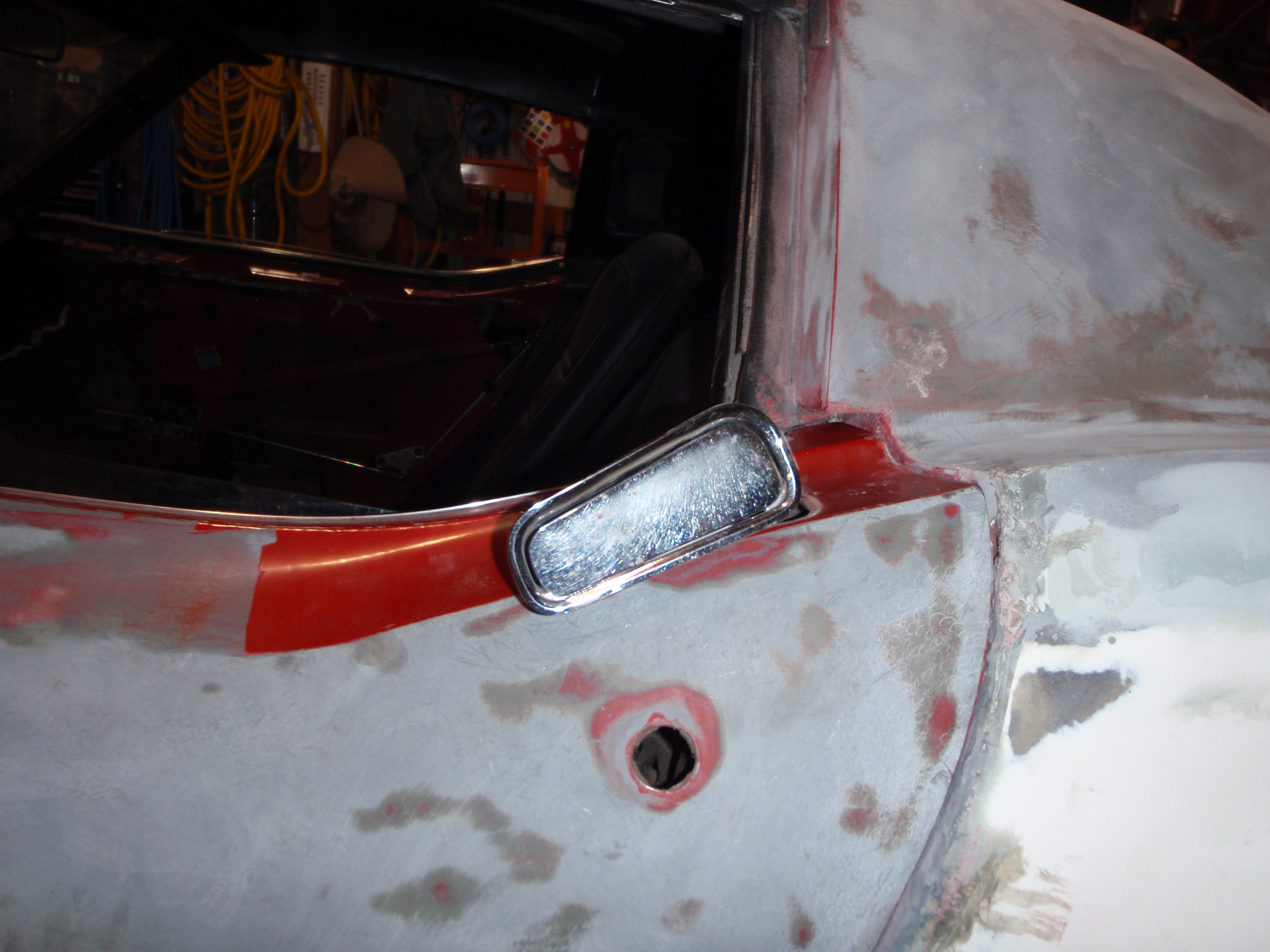
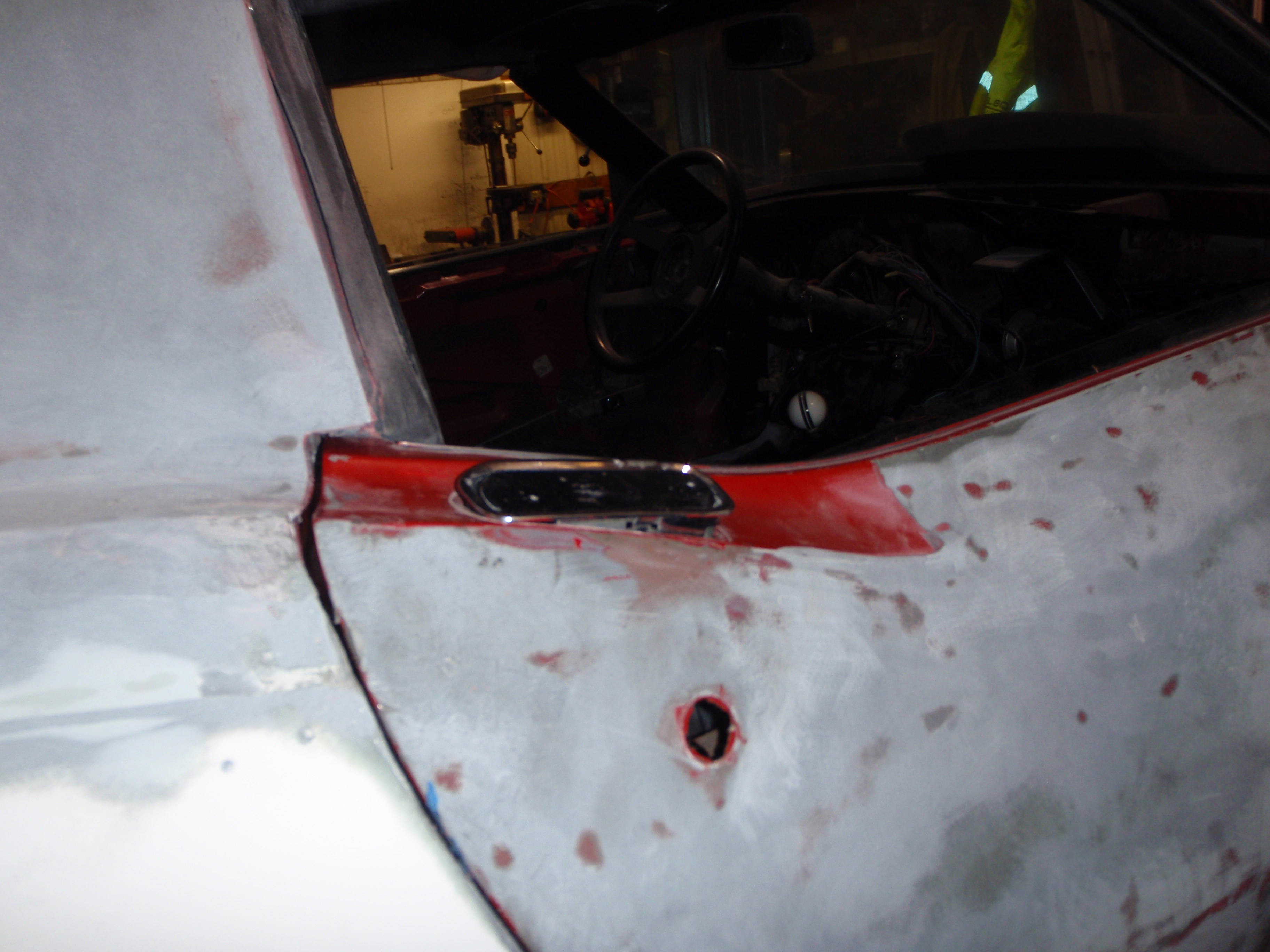
door handles - ugh
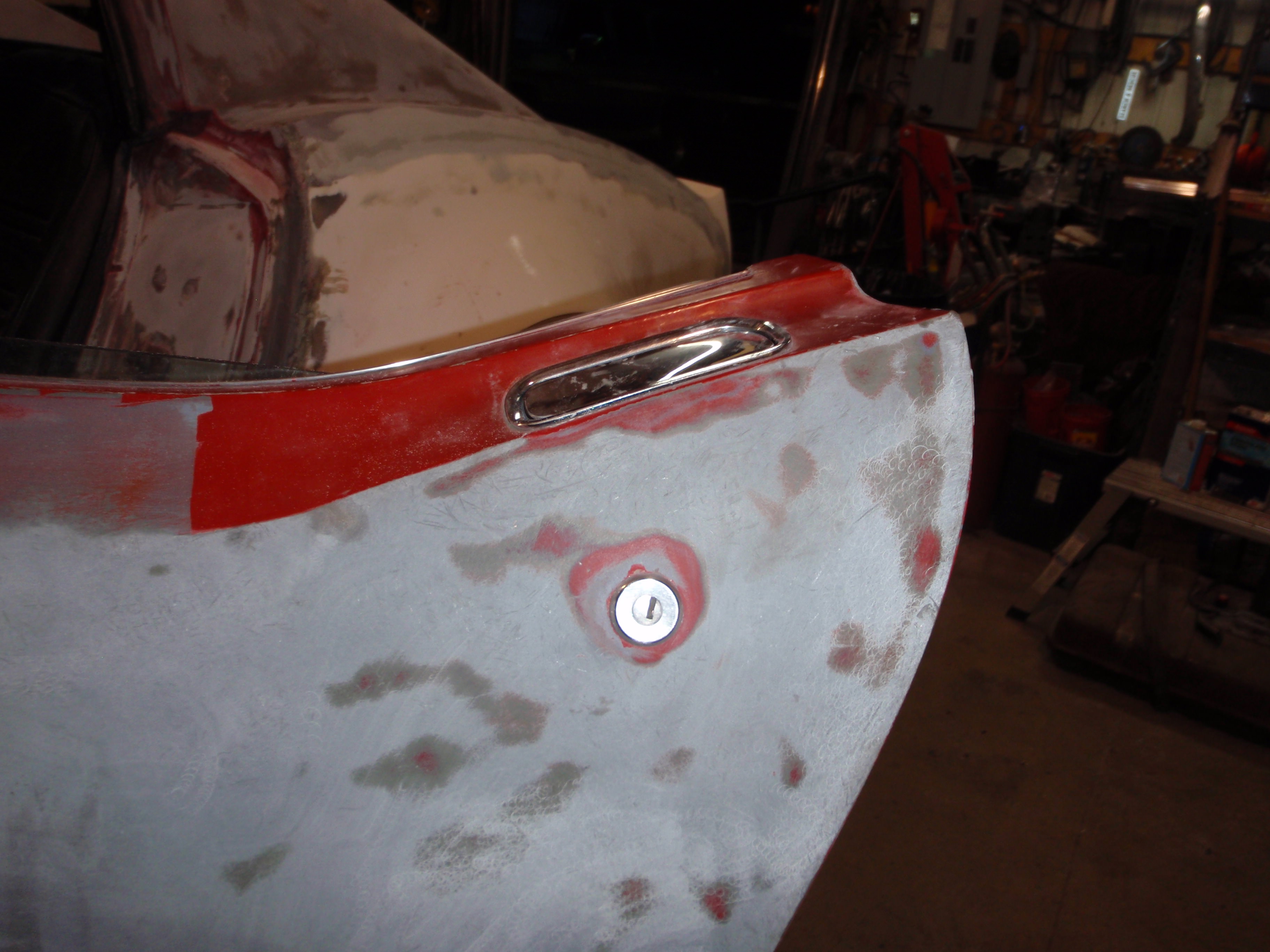
whoa, pretty straight
and this is where I got stopped - there's a clip on the bottom that is not coming off - so rather then go with my next solution that involved a large, hole saw.... I stopped
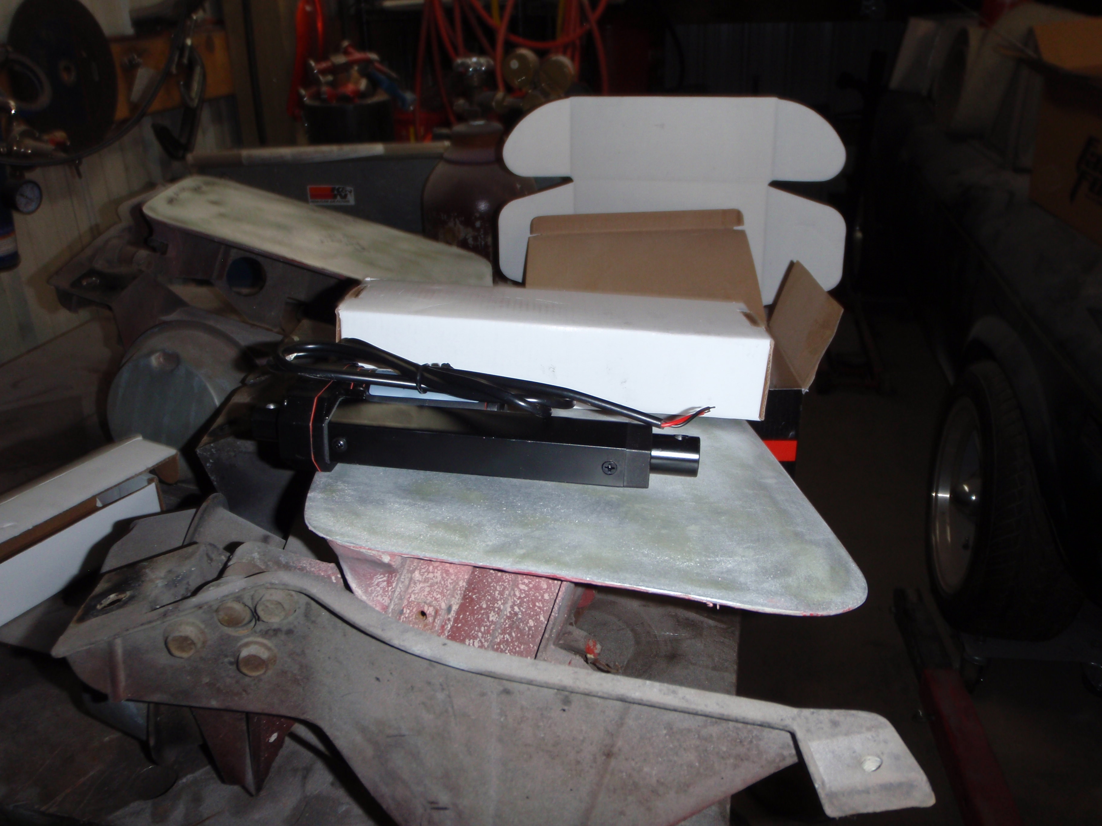
shiny new parts - actuators
anyway, that's all for now
thanks for watching.
whoa, pretty straight
and this is where I got stopped - there's a clip on the bottom that is not coming off - so rather then go with my next solution that involved a large, hole saw.... I stopped
shiny new parts - actuators
anyway, that's all for now
thanks for watching.

 03-29-2018, 11:46 PM
#147
Melting Slicks
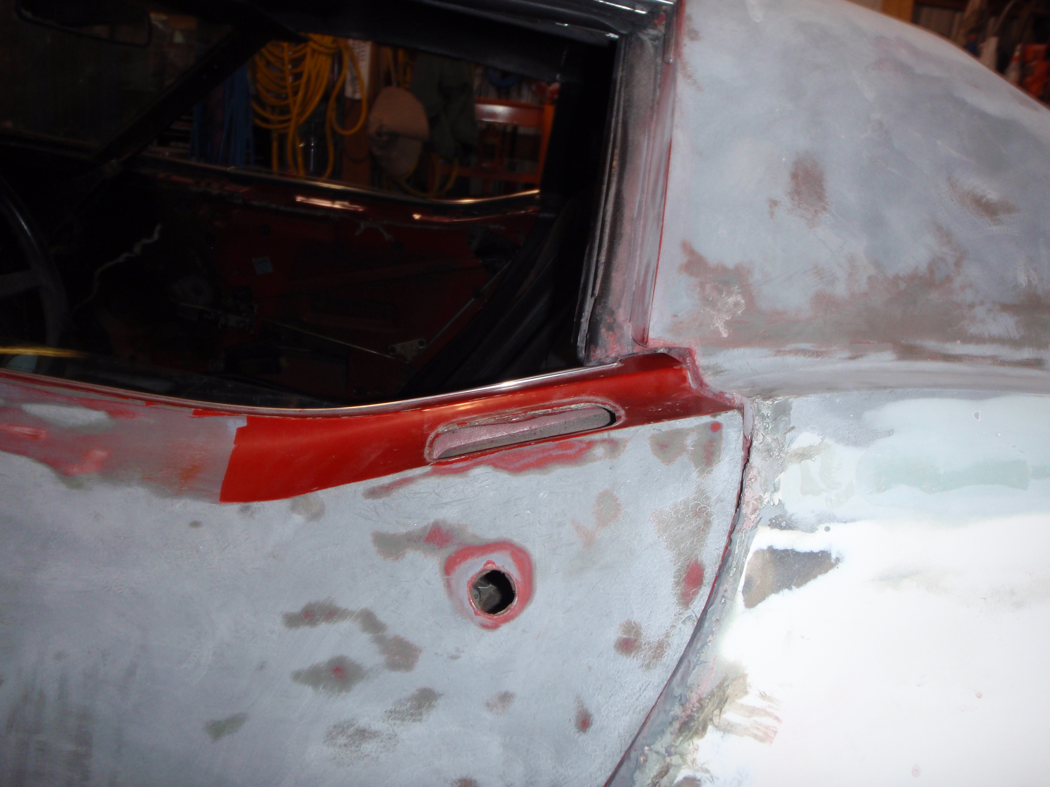
abrcadabra it's off...... how, I have no flippin clue
shiney new part
experimenting with fitment
I had this metal from last time I built an adapter
too tall.... don't have 1/8" stainless
onto the next step of the process
I turned the bracket over to lower it - it's pretty close to where it needs to be
next up will be fabrication brackets.
shiney new part
experimenting with fitment
I had this metal from last time I built an adapter
too tall.... don't have 1/8" stainless
onto the next step of the process
I turned the bracket over to lower it - it's pretty close to where it needs to be
next up will be fabrication brackets.
 04-06-2018, 01:01 AM
#149
Melting Slicks
back to the car
I hate gaps
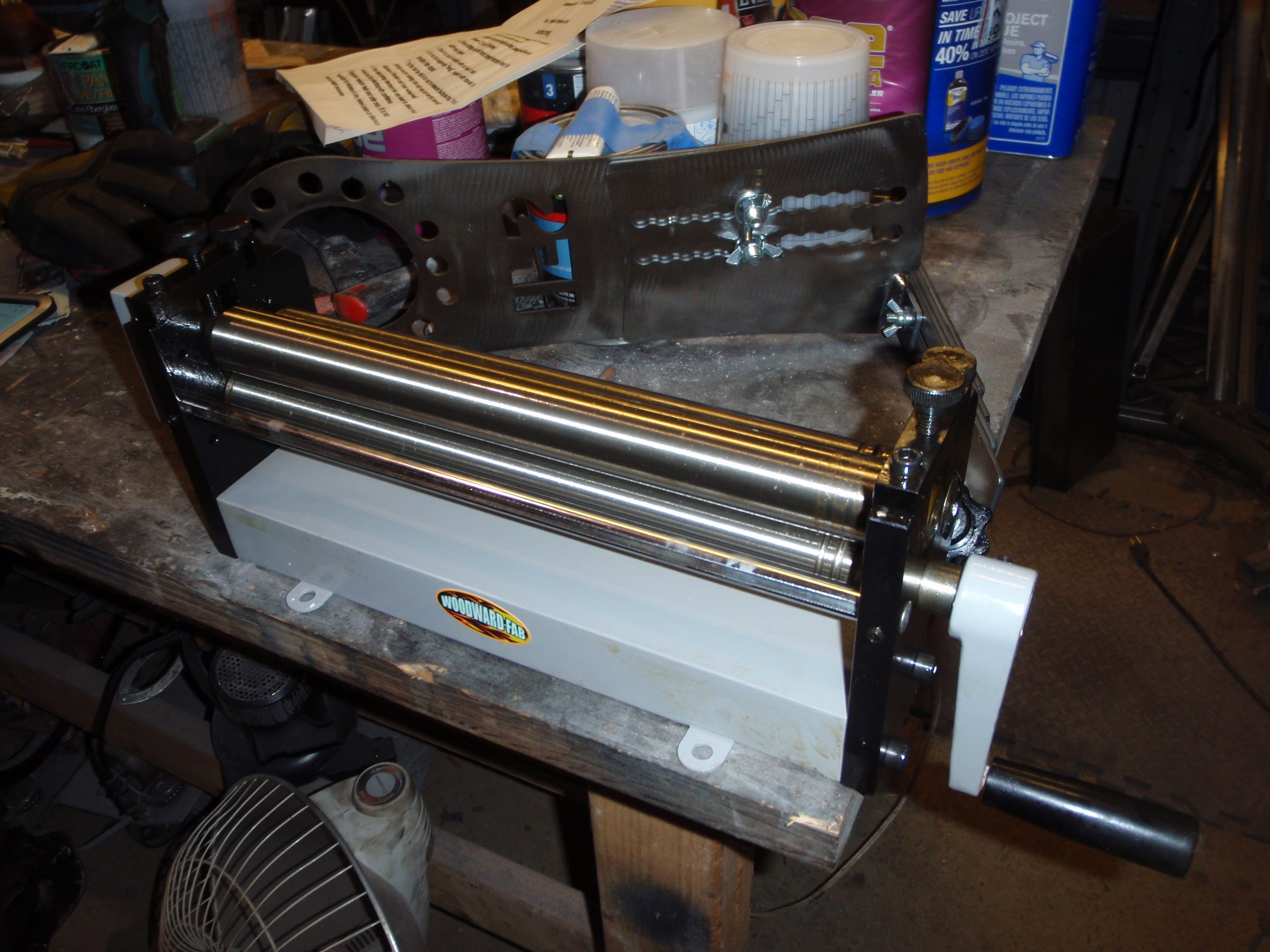
however it does mean shiney new tool
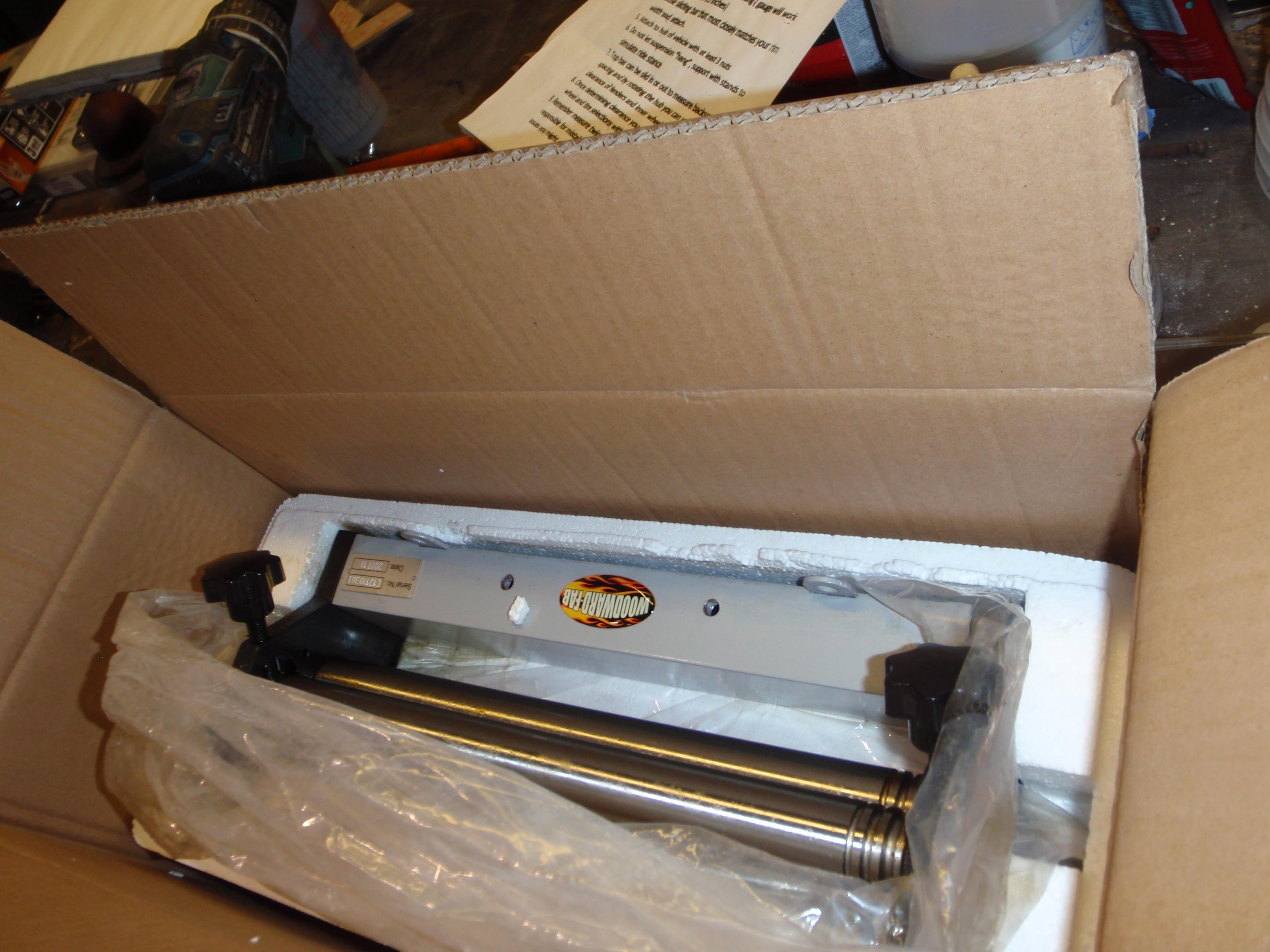
it's so cute
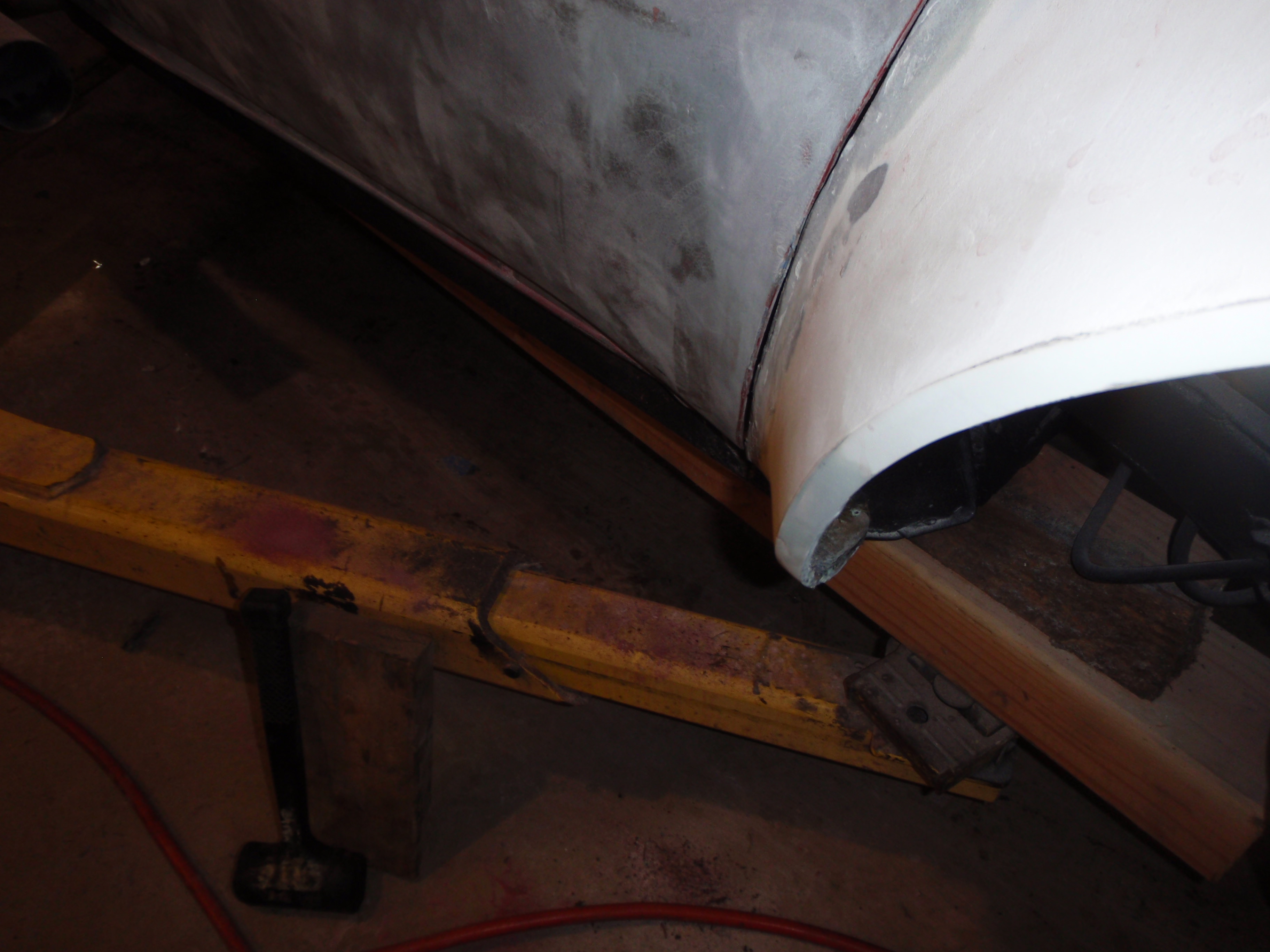
who knew you could convince a fiberglass door to move with a block of wood?
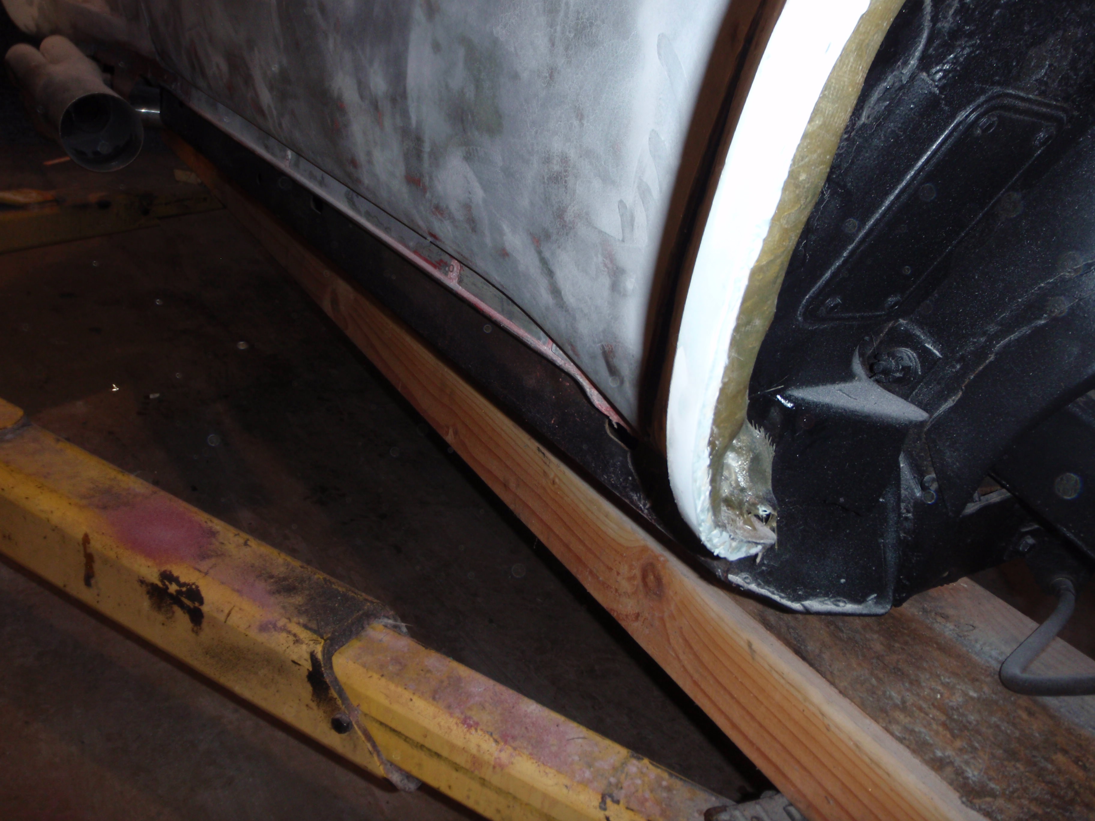
and it does
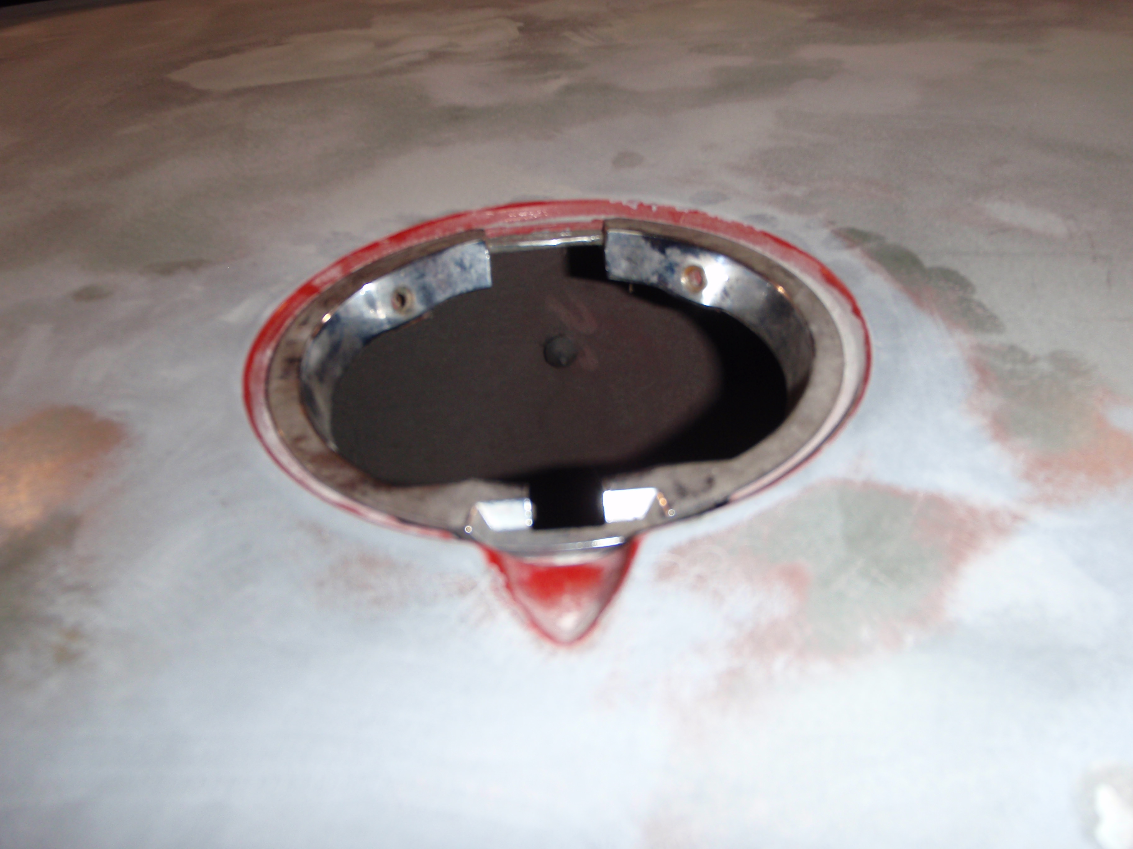
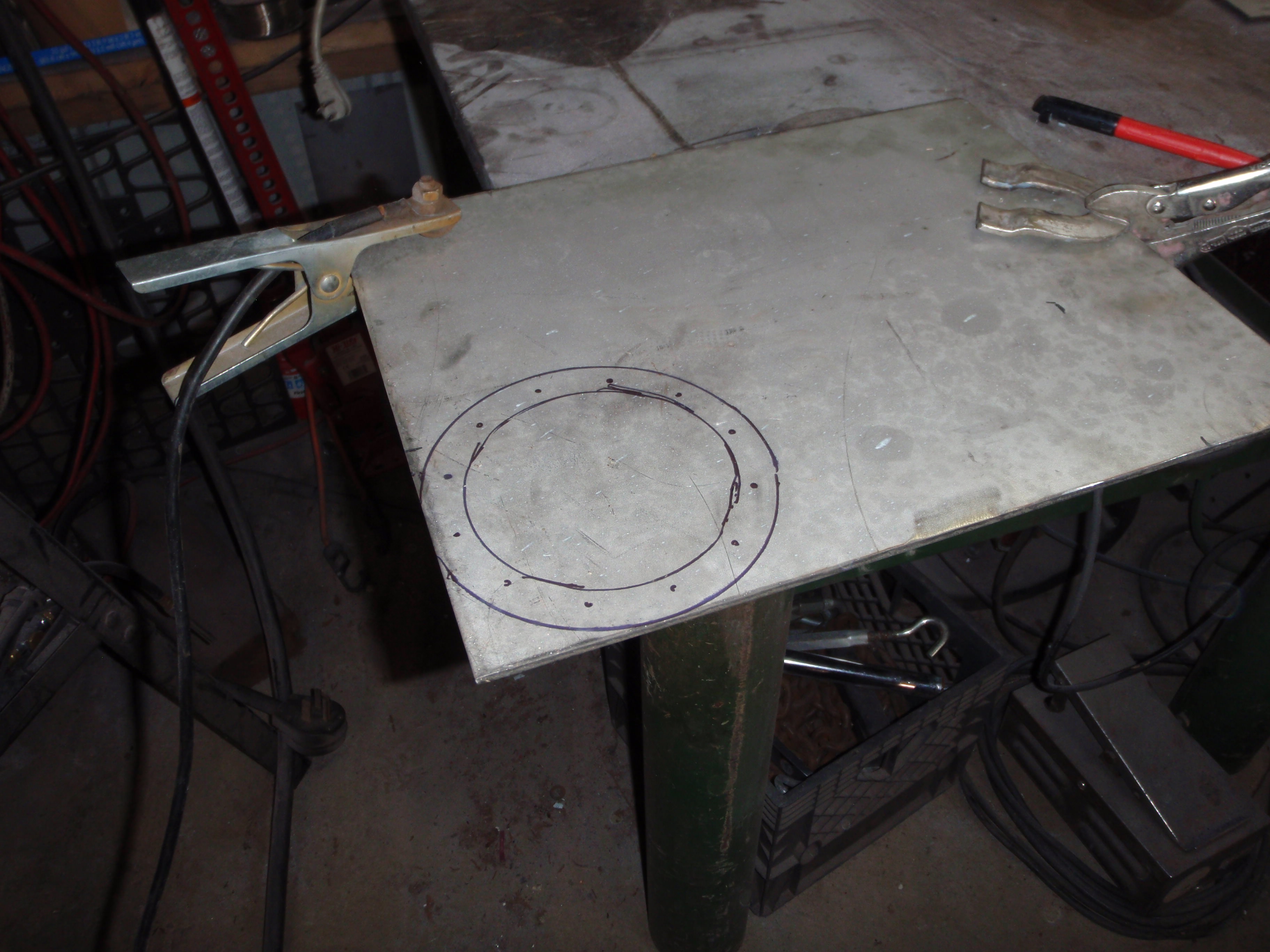
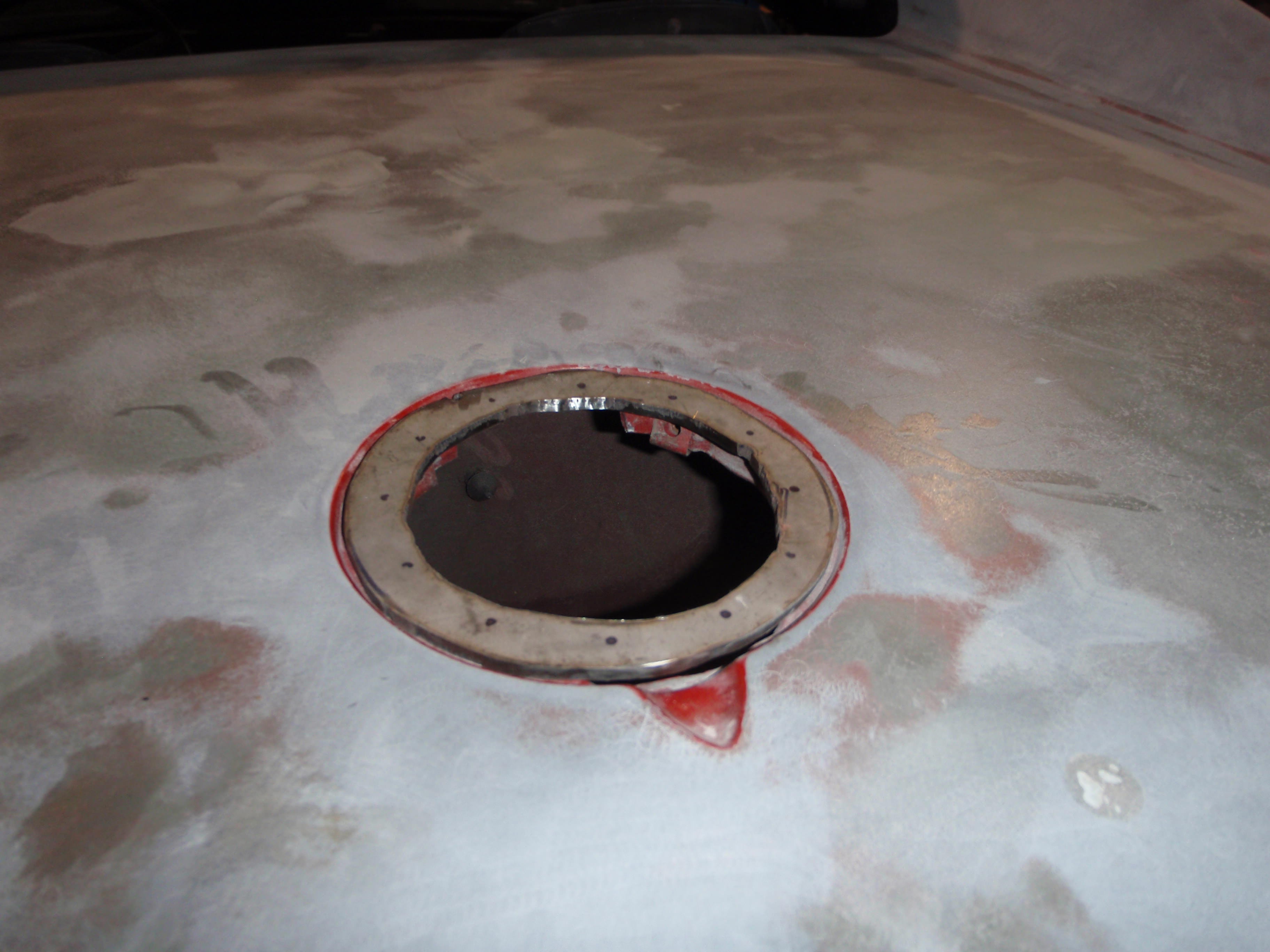
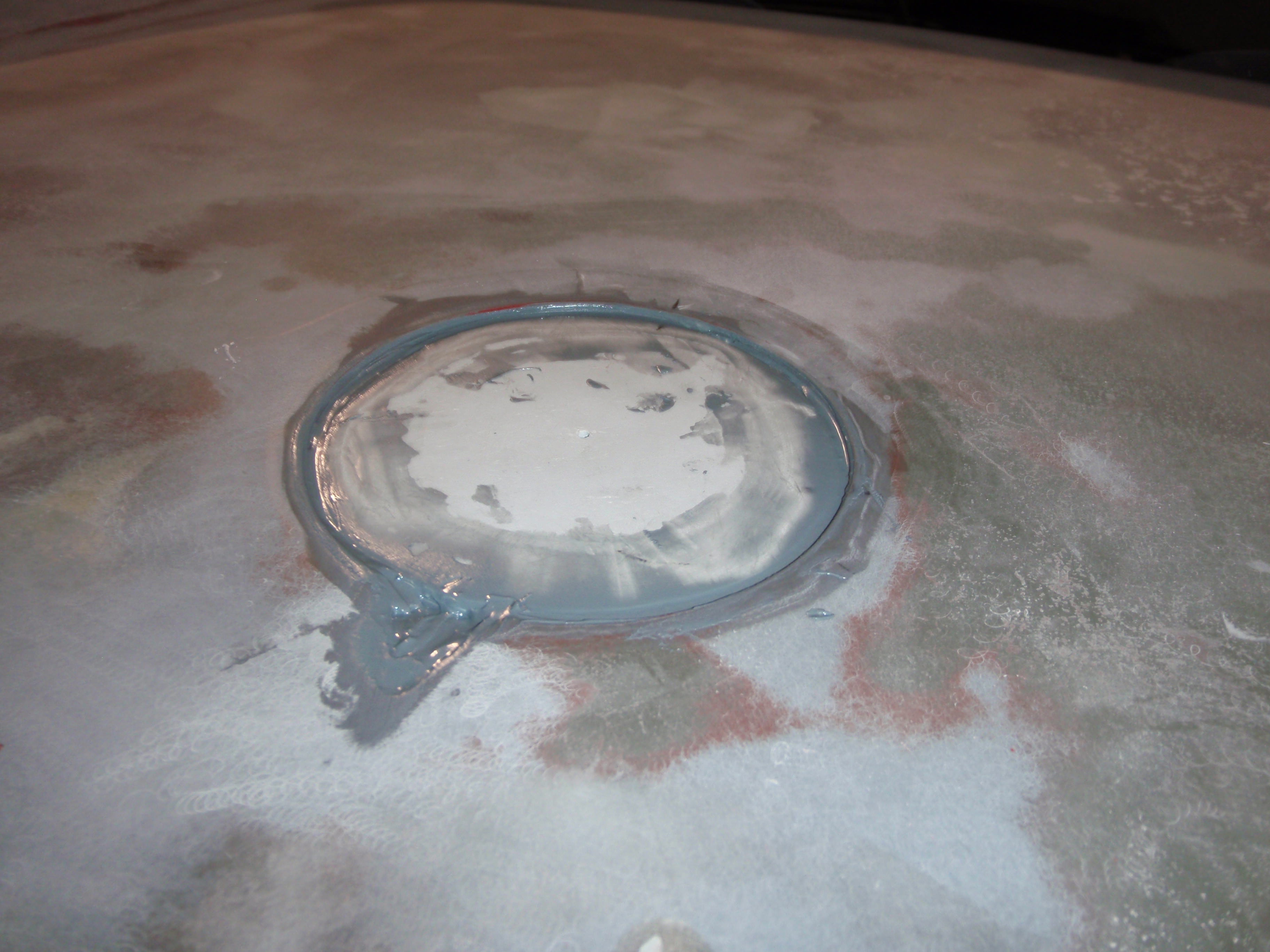
ring time
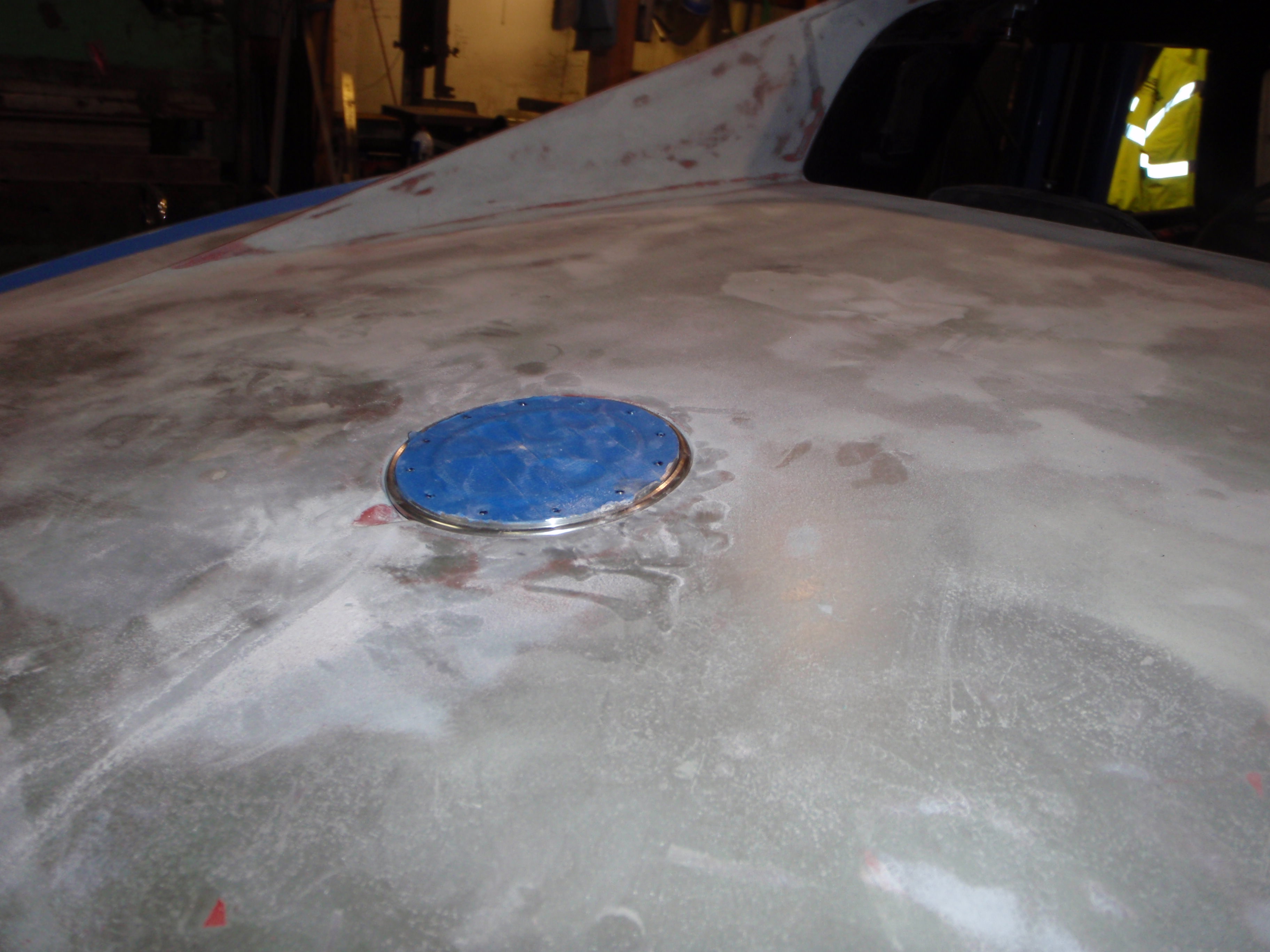
the start of the fix
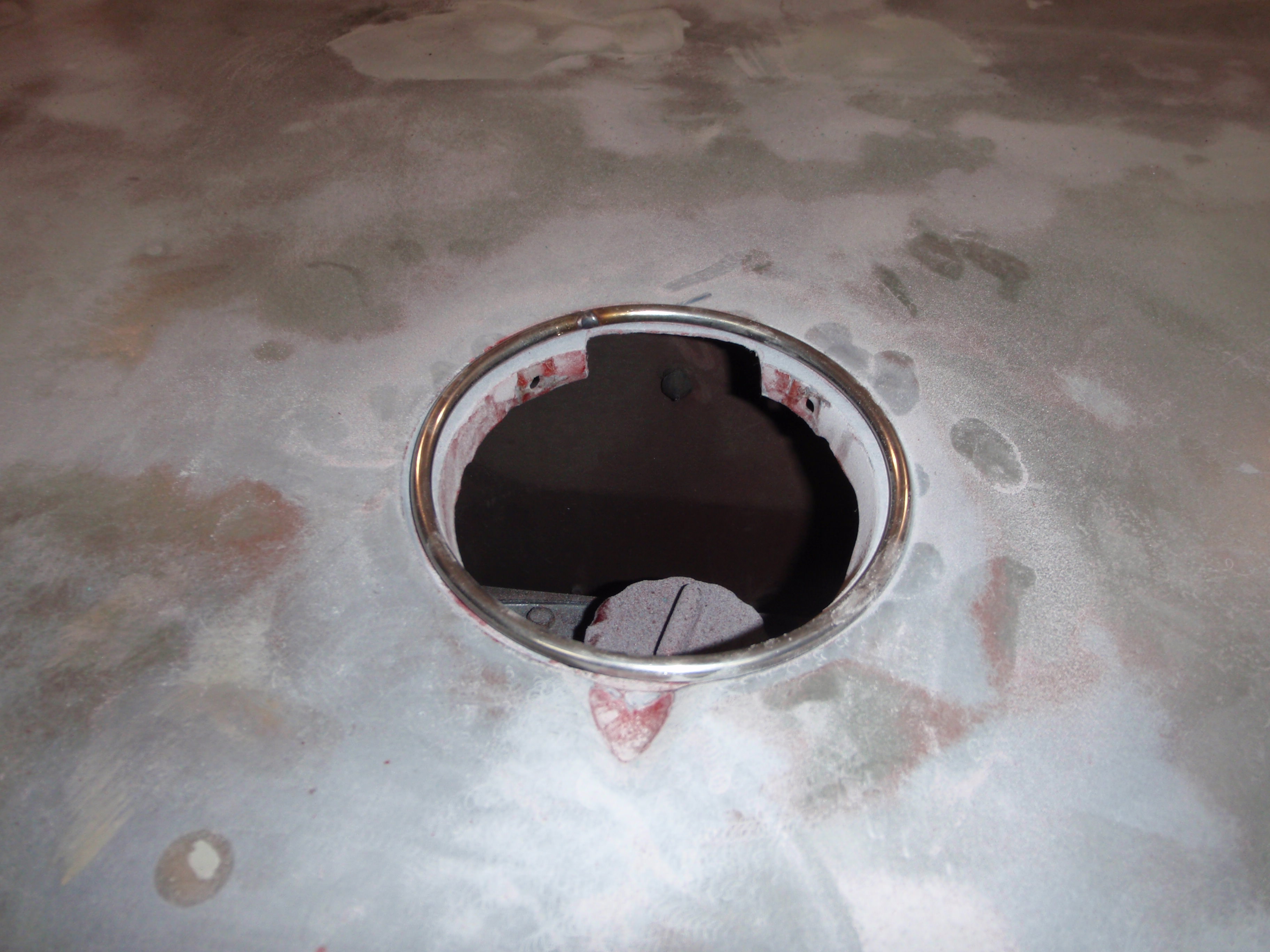
I'm going to flush mount all of this.... the ring is to provide a good edge
ugh back to gaps
I'm not looking forward to the sanding portion of this endeavor
I hate gaps
however it does mean shiney new tool
it's so cute
who knew you could convince a fiberglass door to move with a block of wood?
and it does
ring time
the start of the fix
I'm going to flush mount all of this.... the ring is to provide a good edge
ugh back to gaps
I'm not looking forward to the sanding portion of this endeavor
04-06-2018, 09:58 AM
#150
Nam Labrat
Member Since: Sep 2013
Location: New Orleans Loo-z-anna
Posts: 33,893
Received 4,173 Likes
on
2,735 Posts
I understand.....I'm still itching from reworking my door gaps 
The following users liked this post:
Metalhead140 (04-10-2018)
04-11-2018, 12:27 AM
#152
Melting Slicks
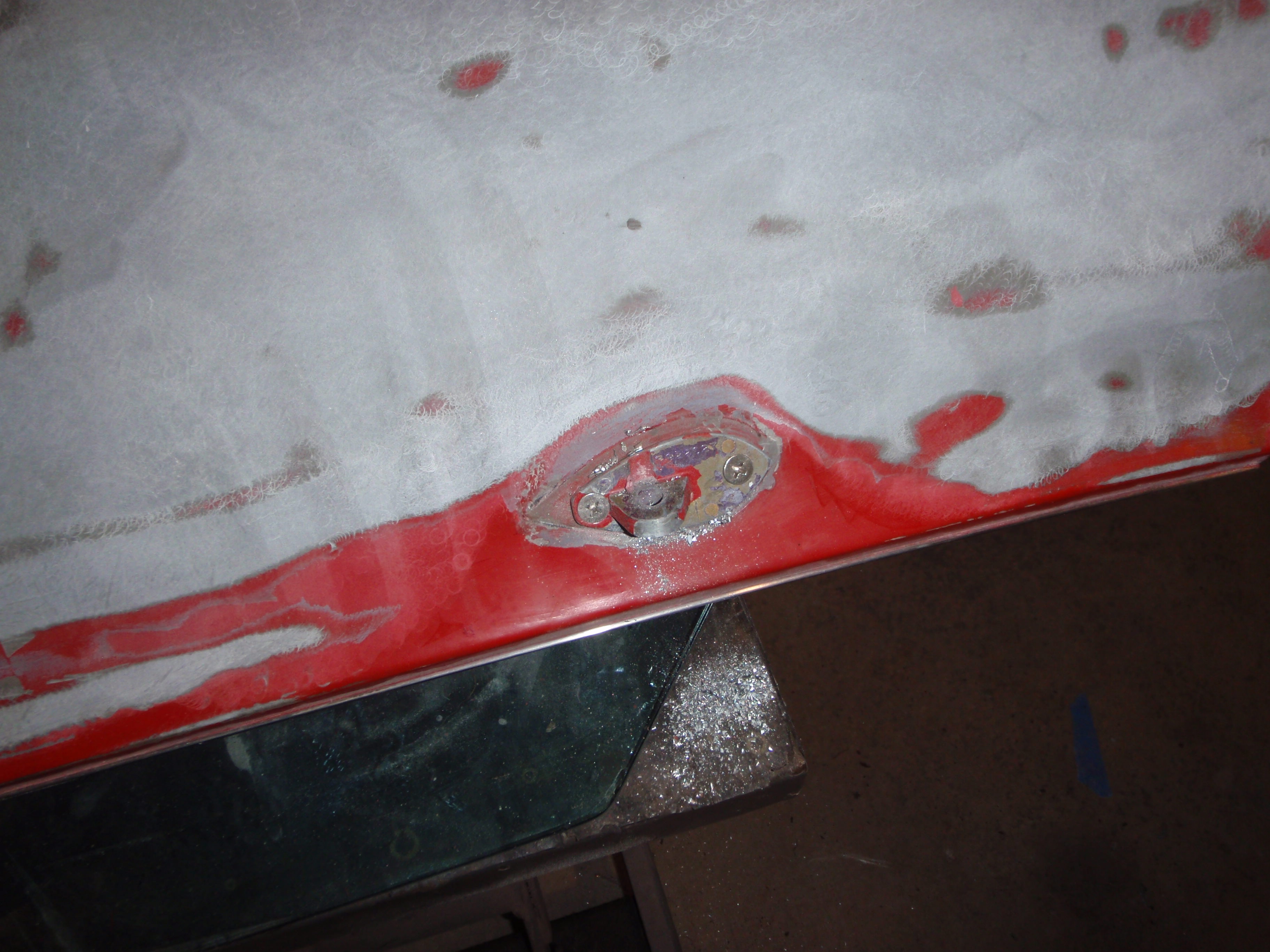
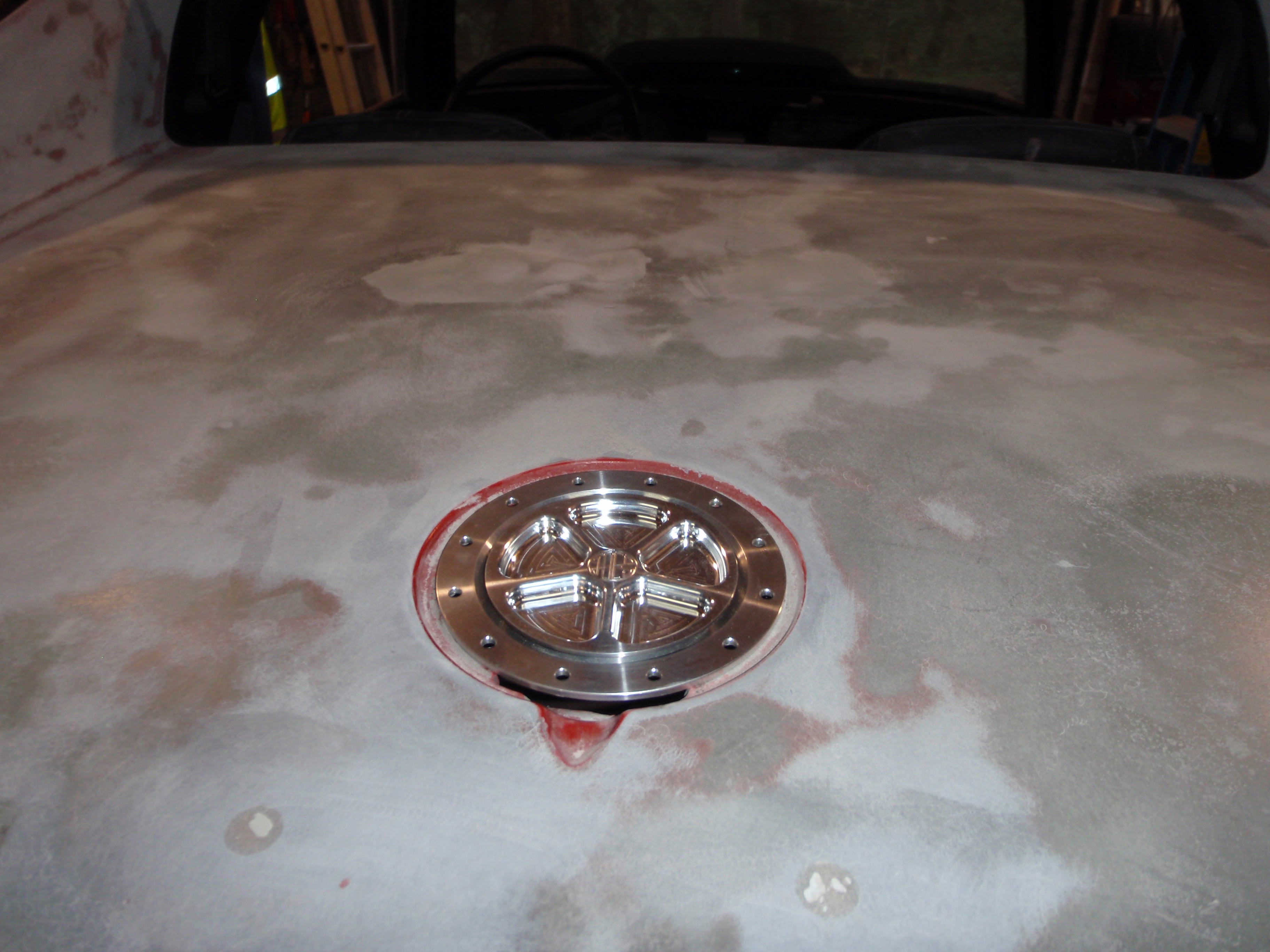
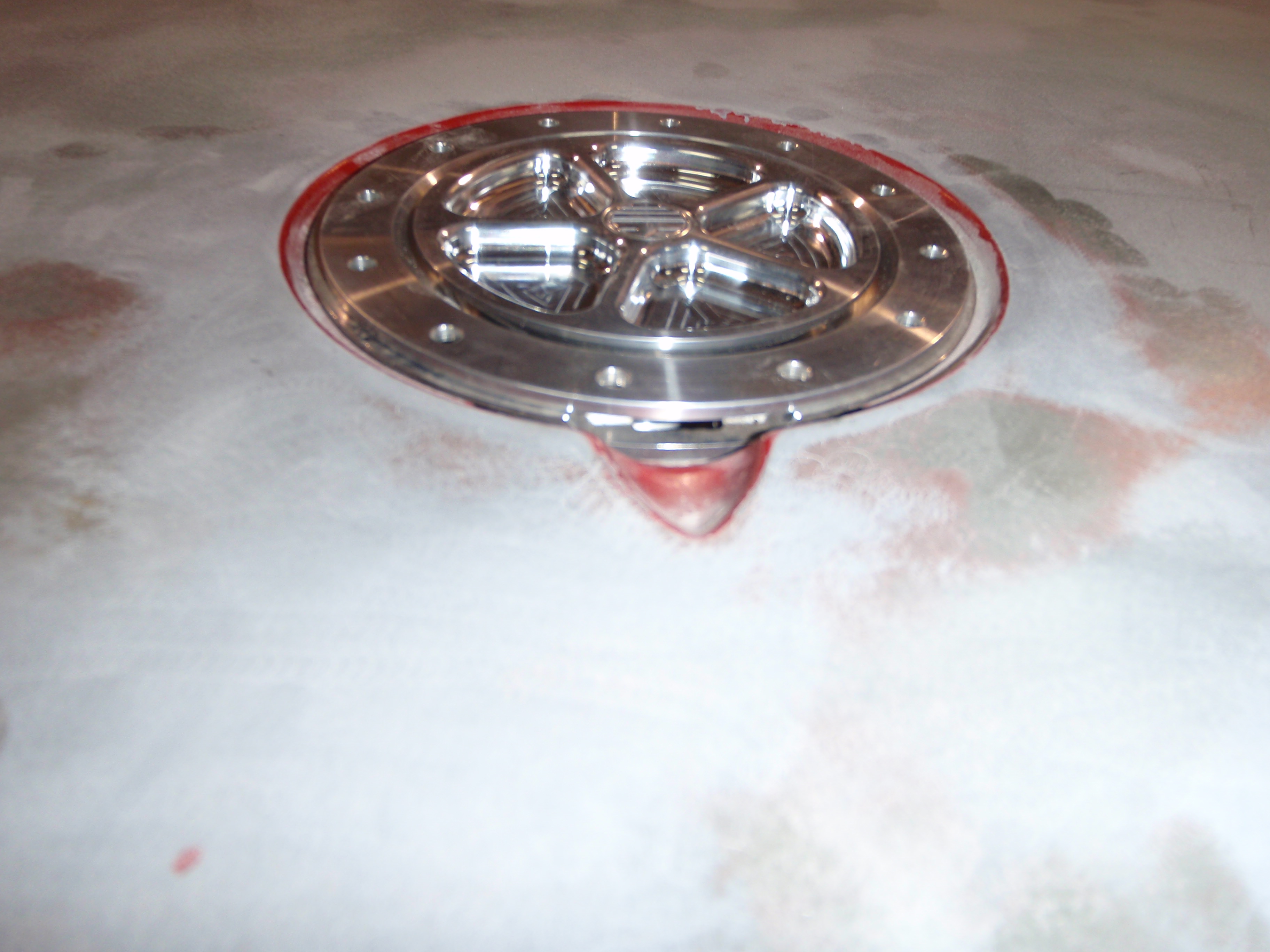
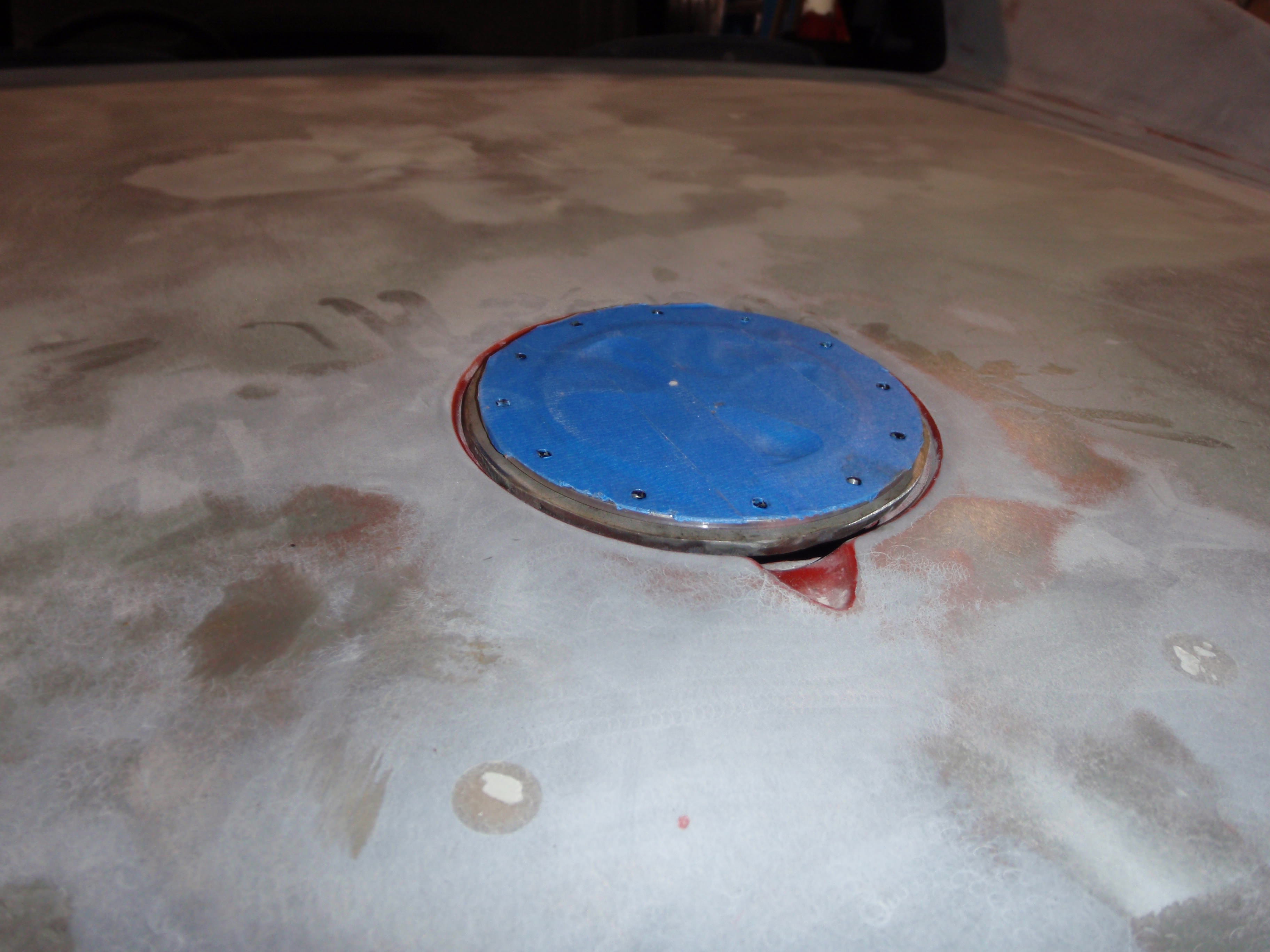
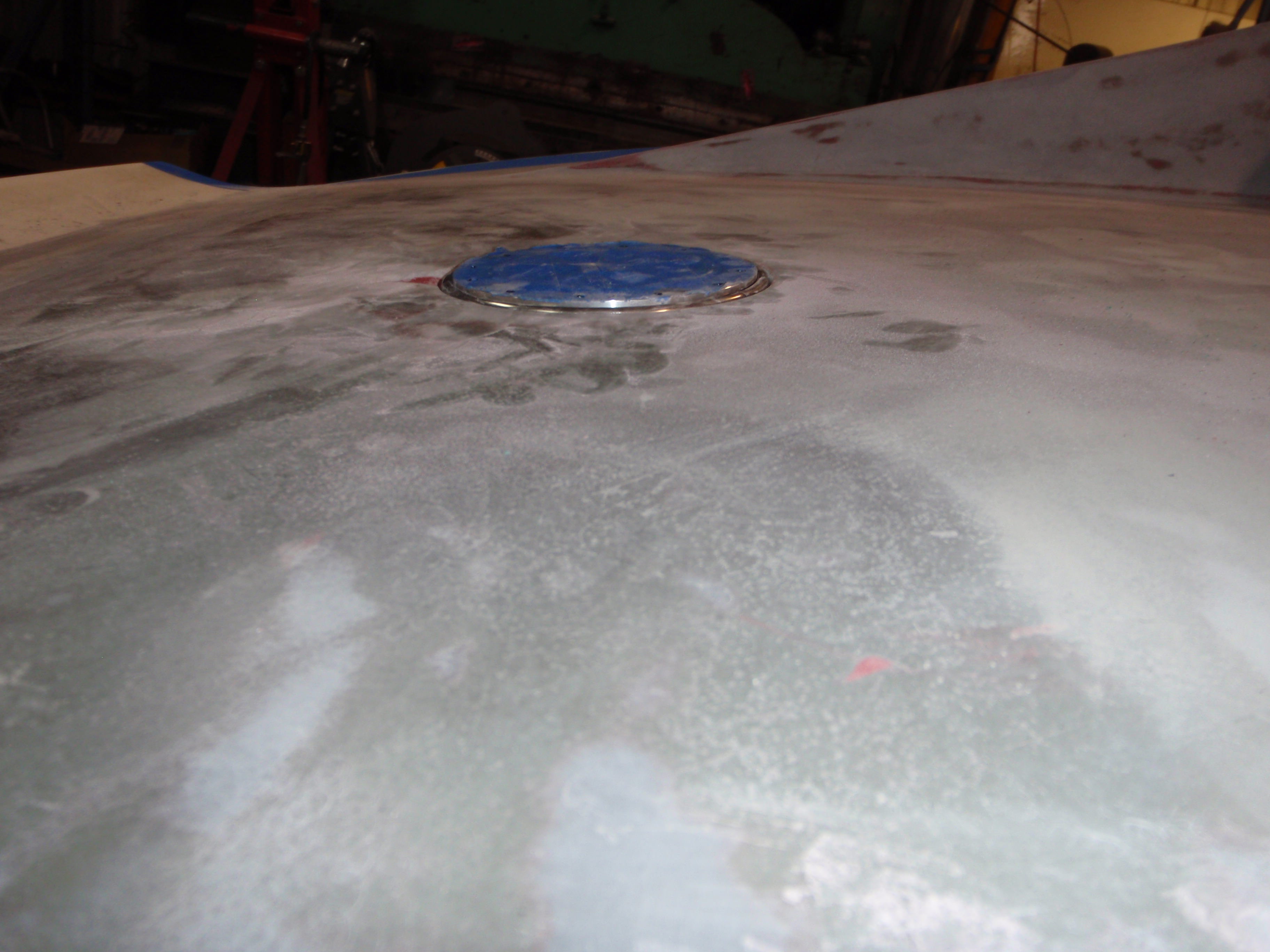
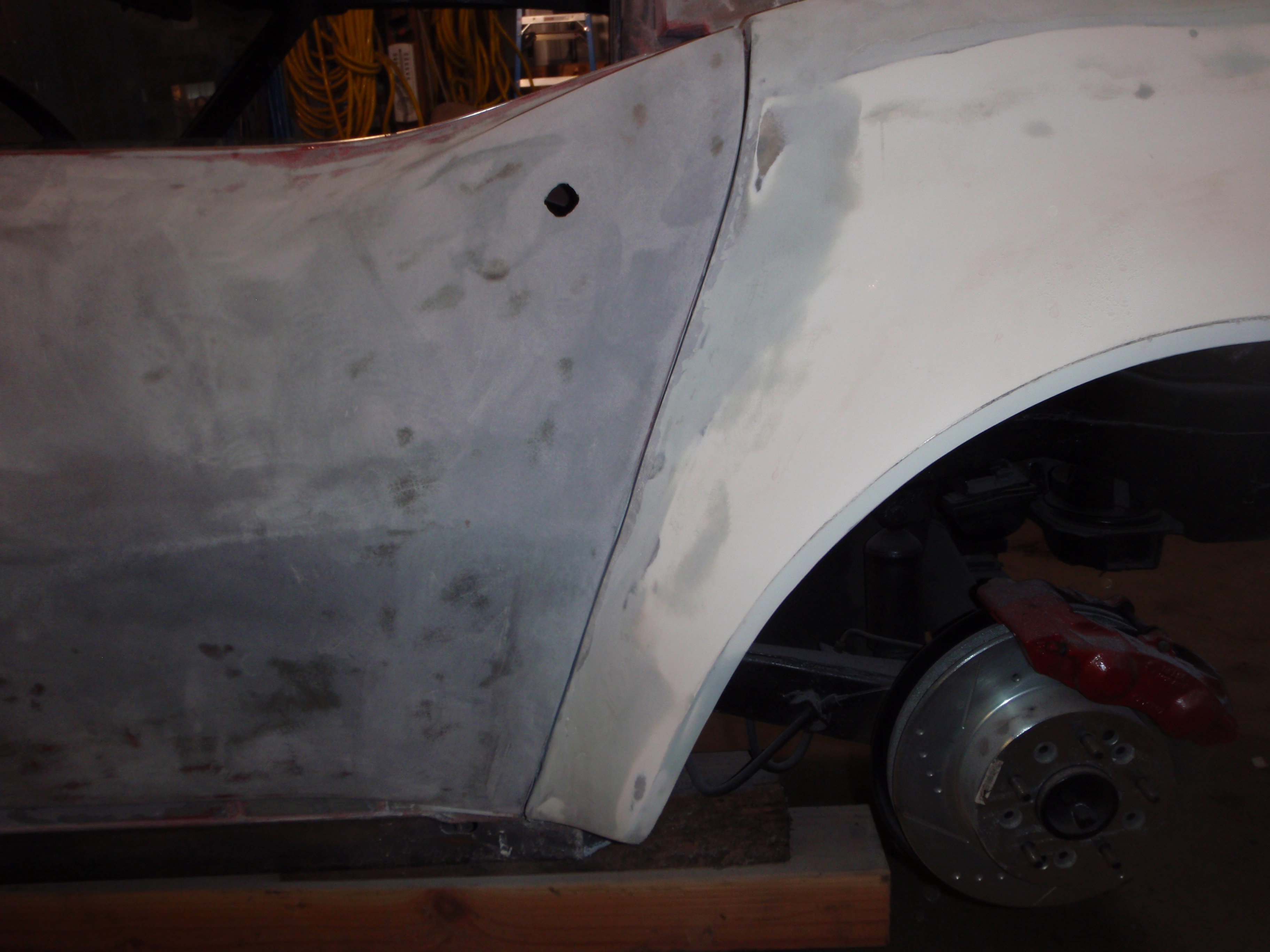
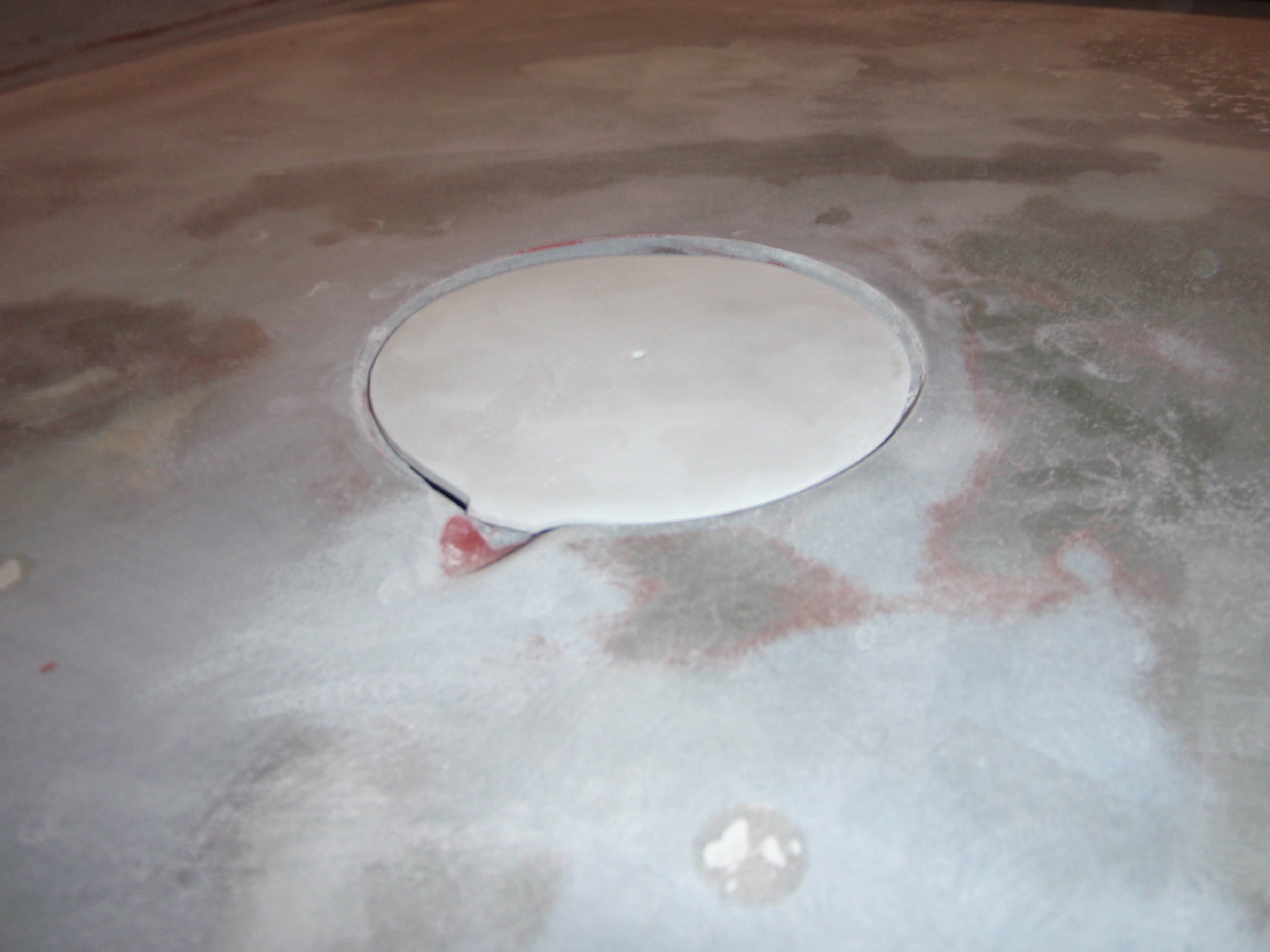
time to fill the hole in the deck
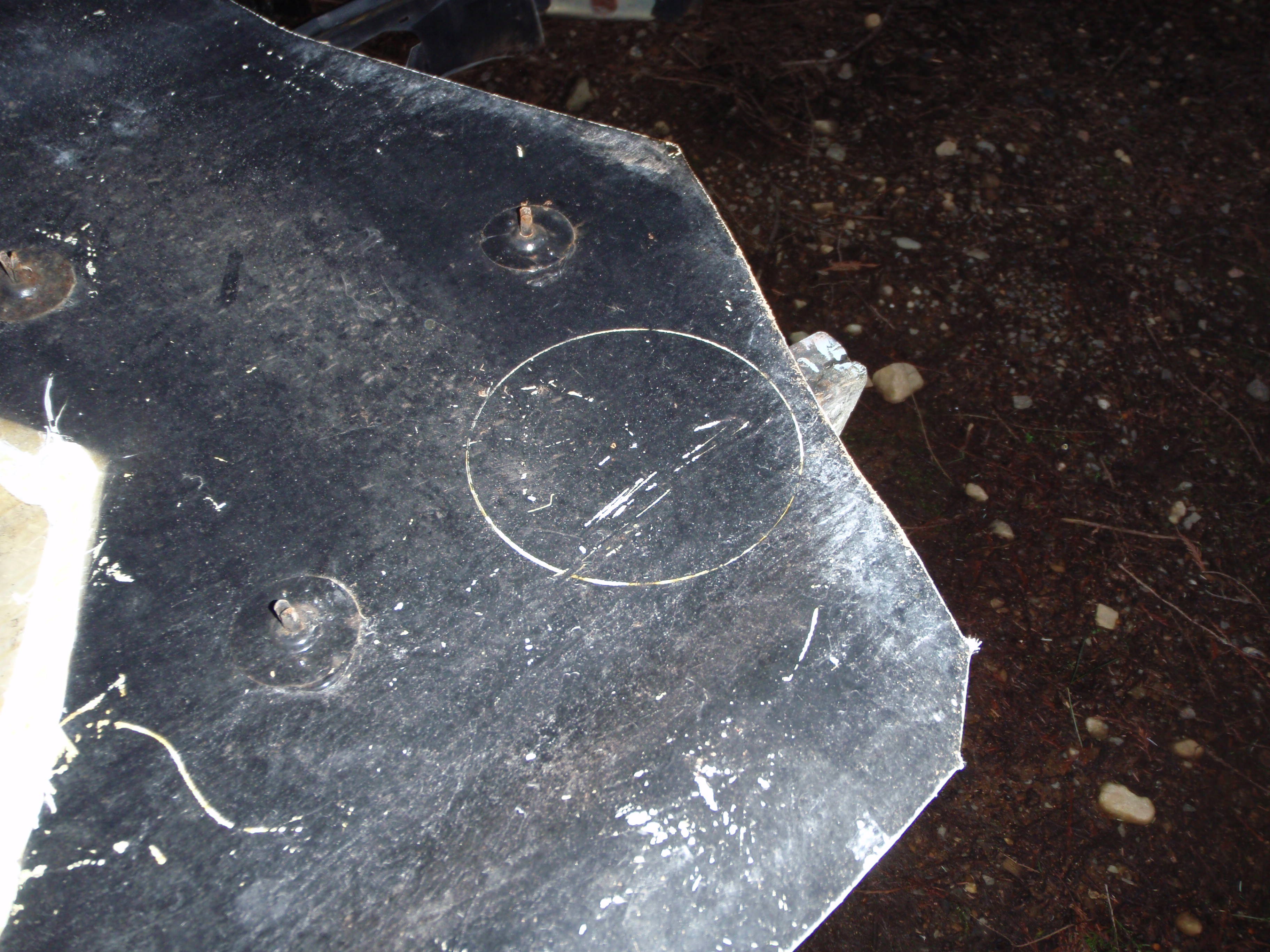
looks to be about the right depth now
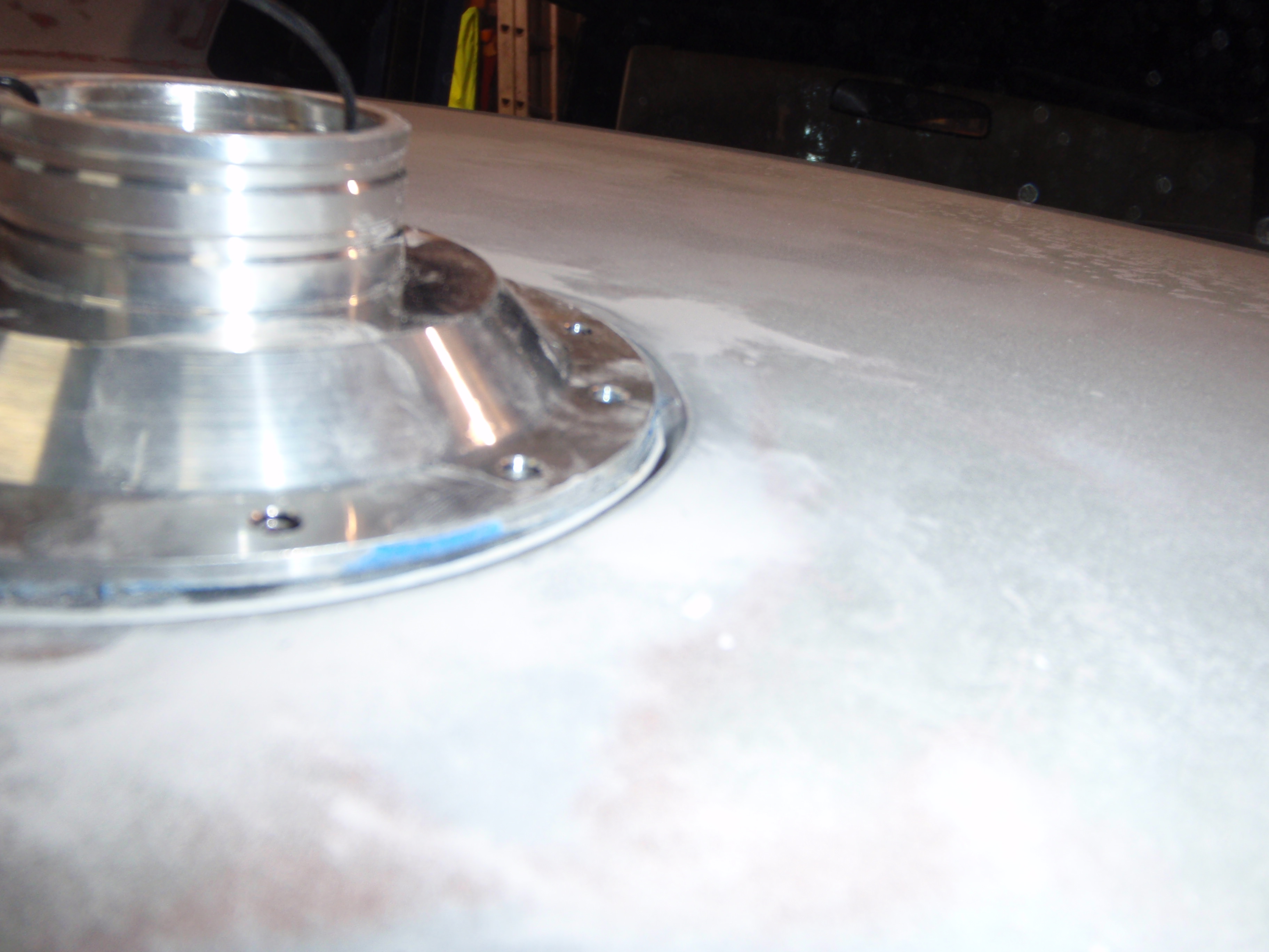
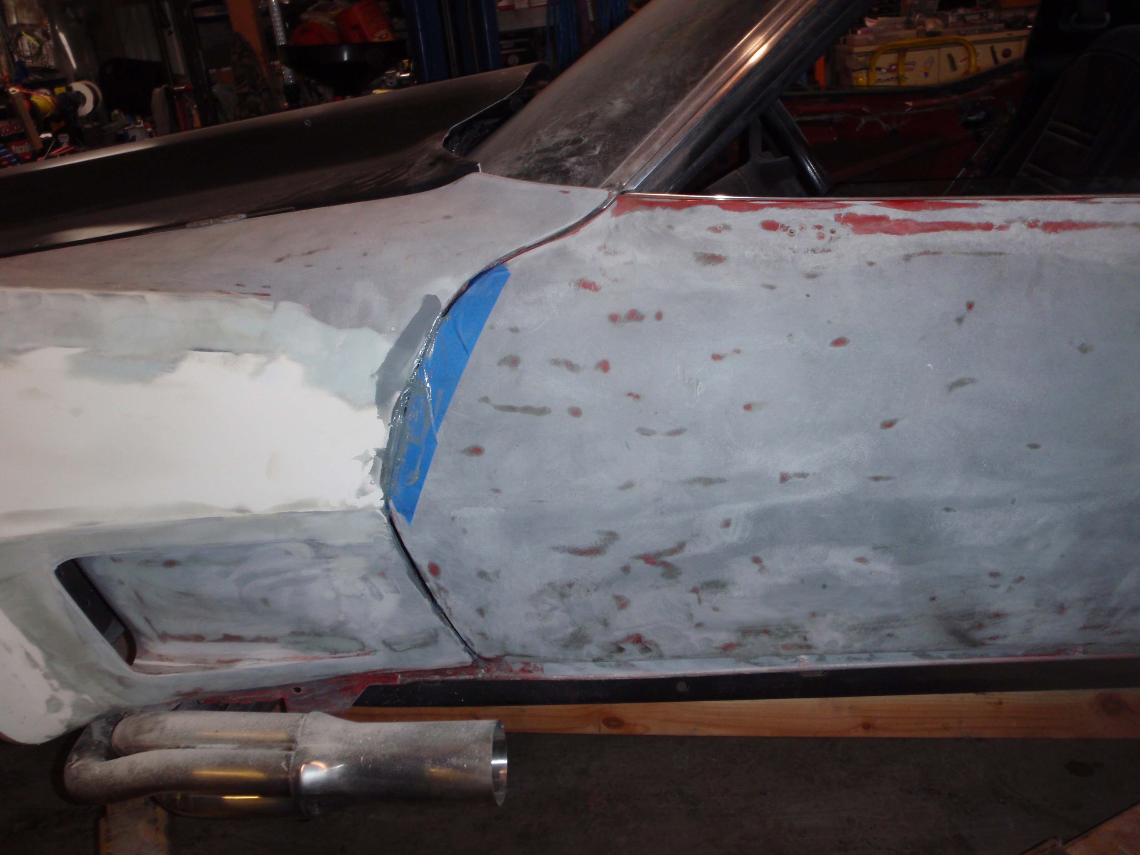
and fitting time *hack*
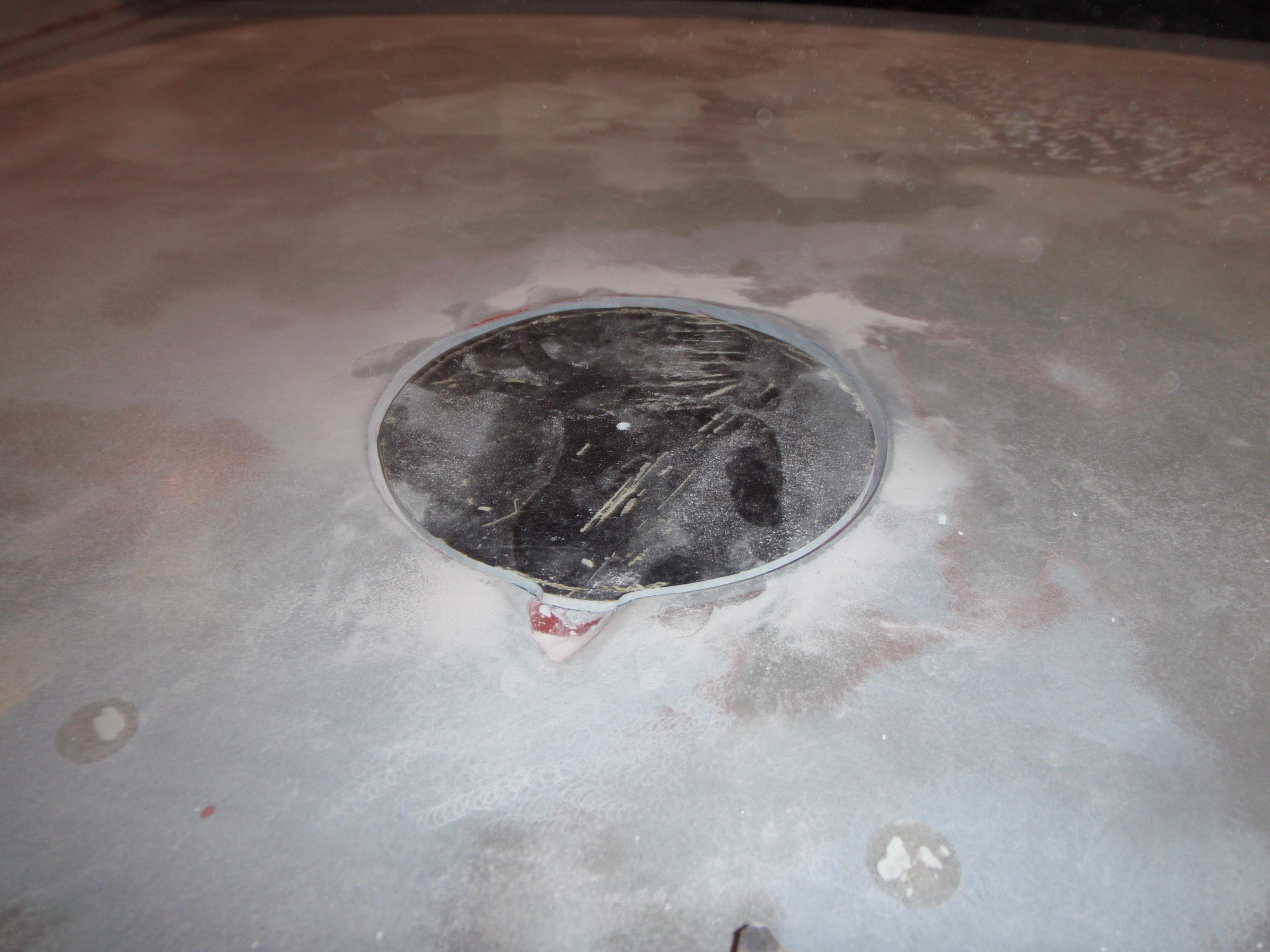
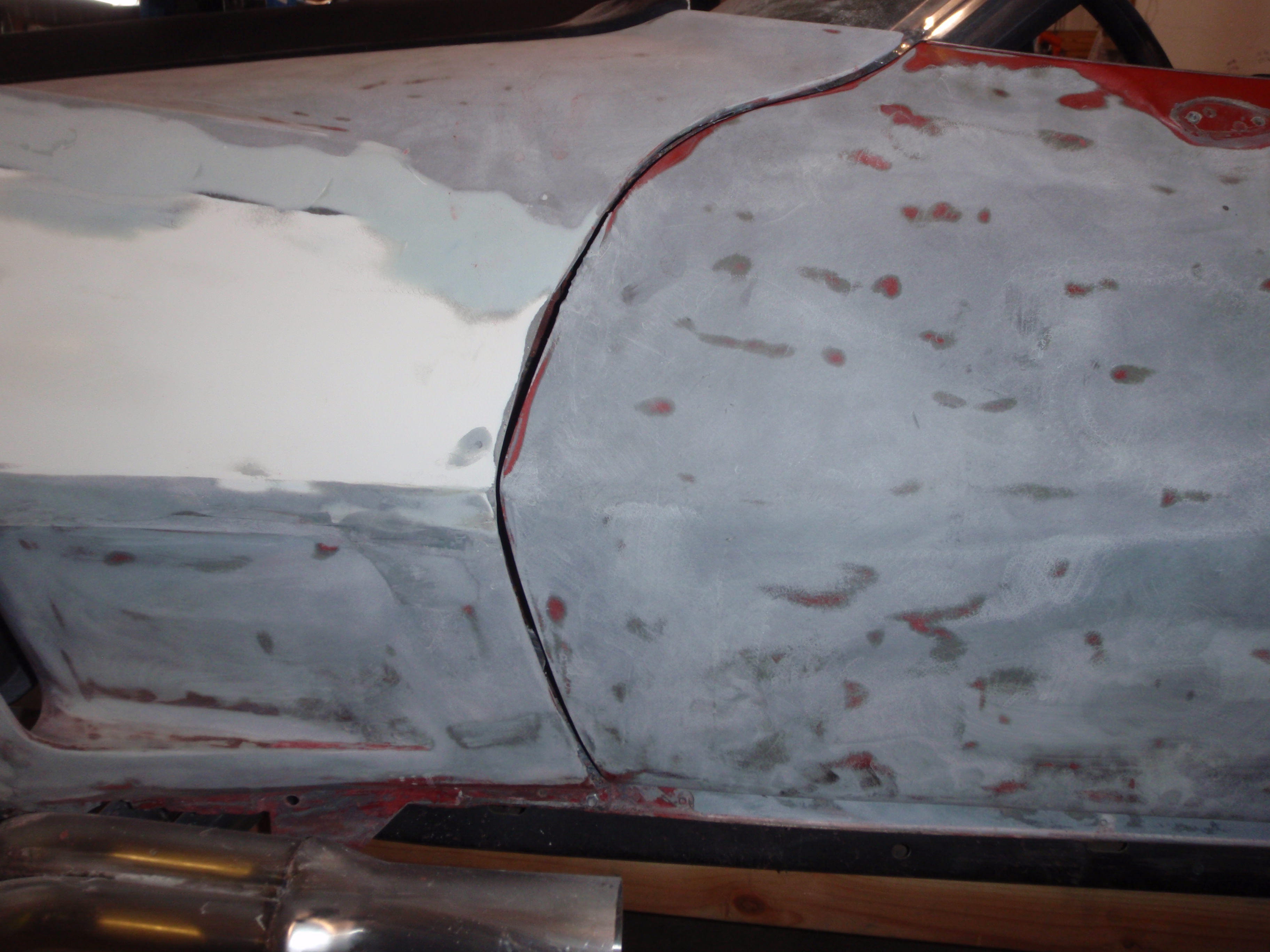
close
glued
not close
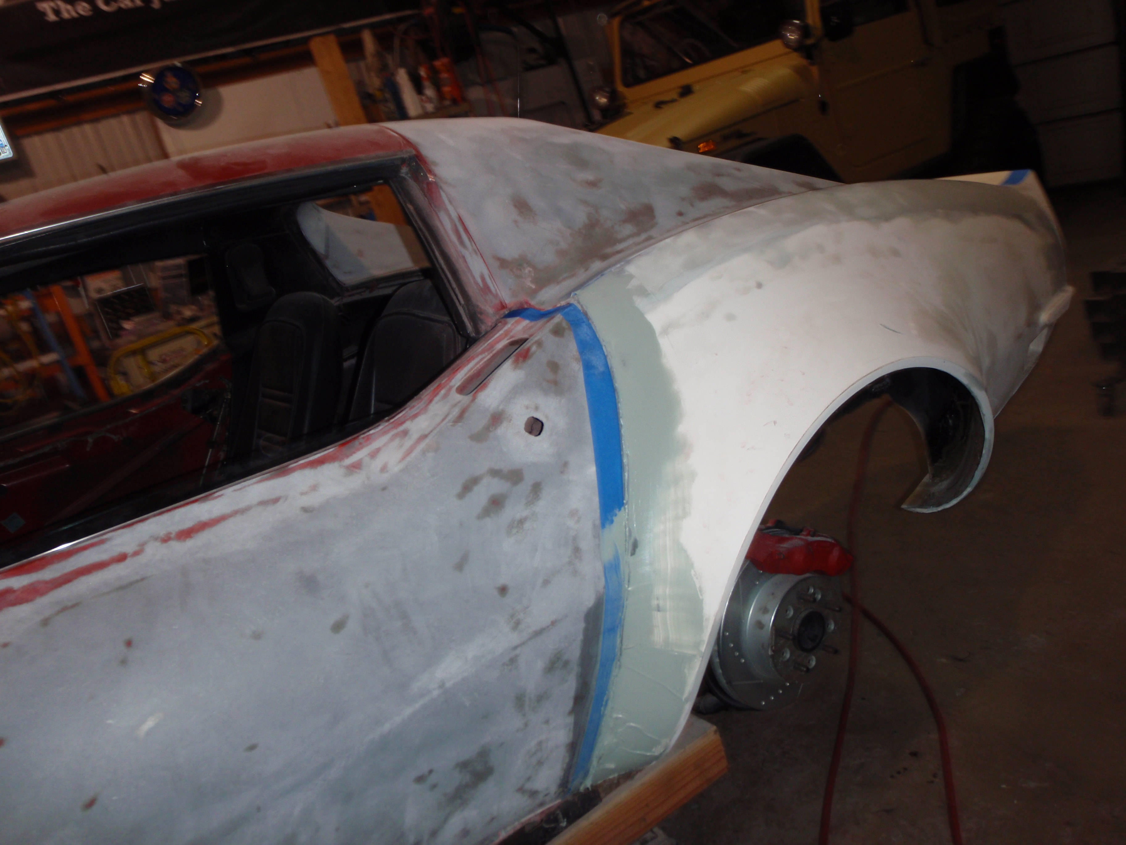
hmmm... is it supposed to veer off to the left? wonder what that would do for aero?
maybe I can counter balance that with a step on the right side?
hmmm.... glue it - nice to have lots of clamps
and as if by magic, it's now lined up.... if anyone asks, it was totally accidental and I have no idea what happened
looks to be about the right depth now
and fitting time *hack*
close
glued
not close
hmmm... is it supposed to veer off to the left? wonder what that would do for aero?
maybe I can counter balance that with a step on the right side?
hmmm.... glue it - nice to have lots of clamps
and as if by magic, it's now lined up.... if anyone asks, it was totally accidental and I have no idea what happened
04-12-2018, 04:01 PM
#153
Melting Slicks
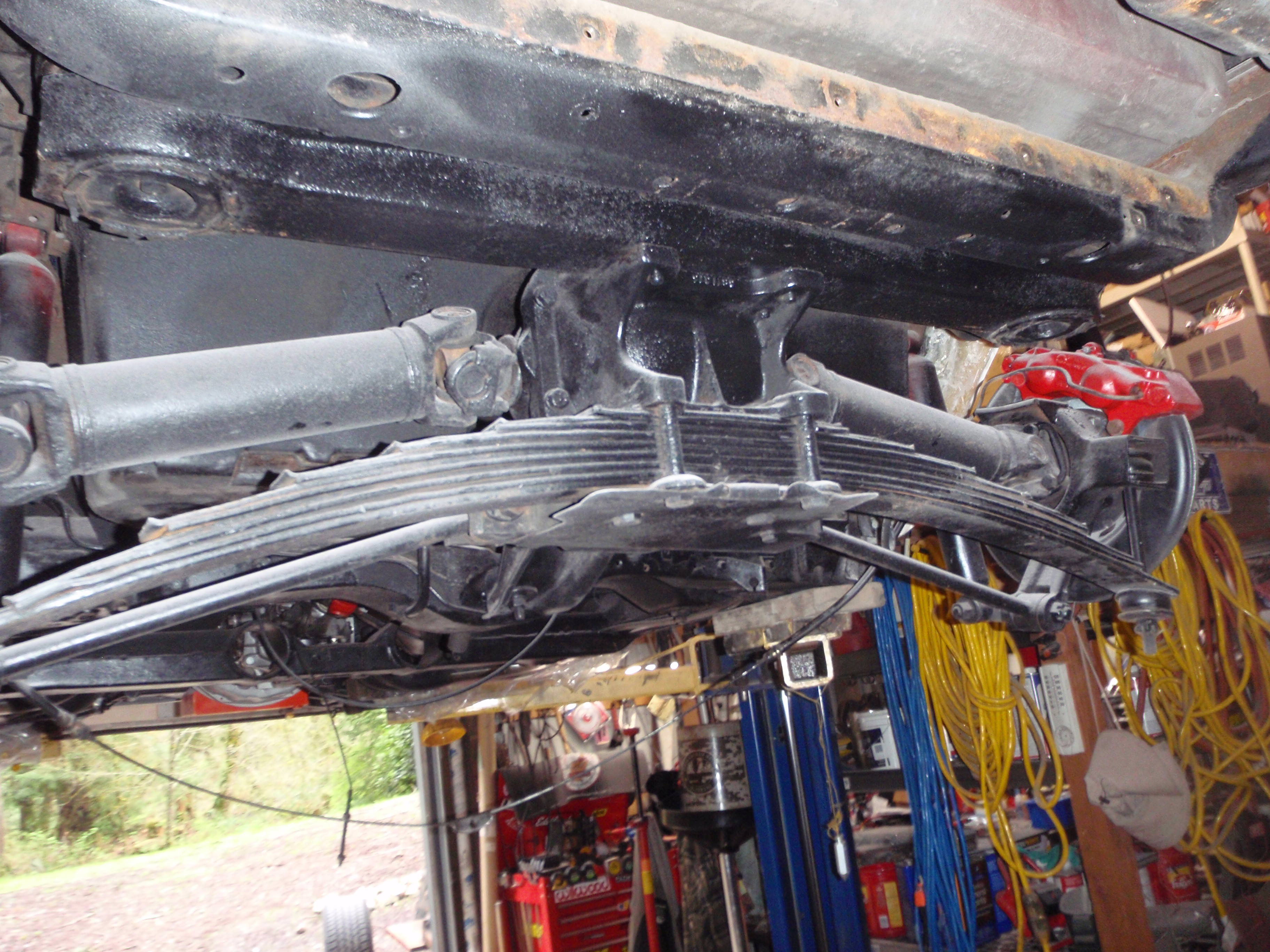
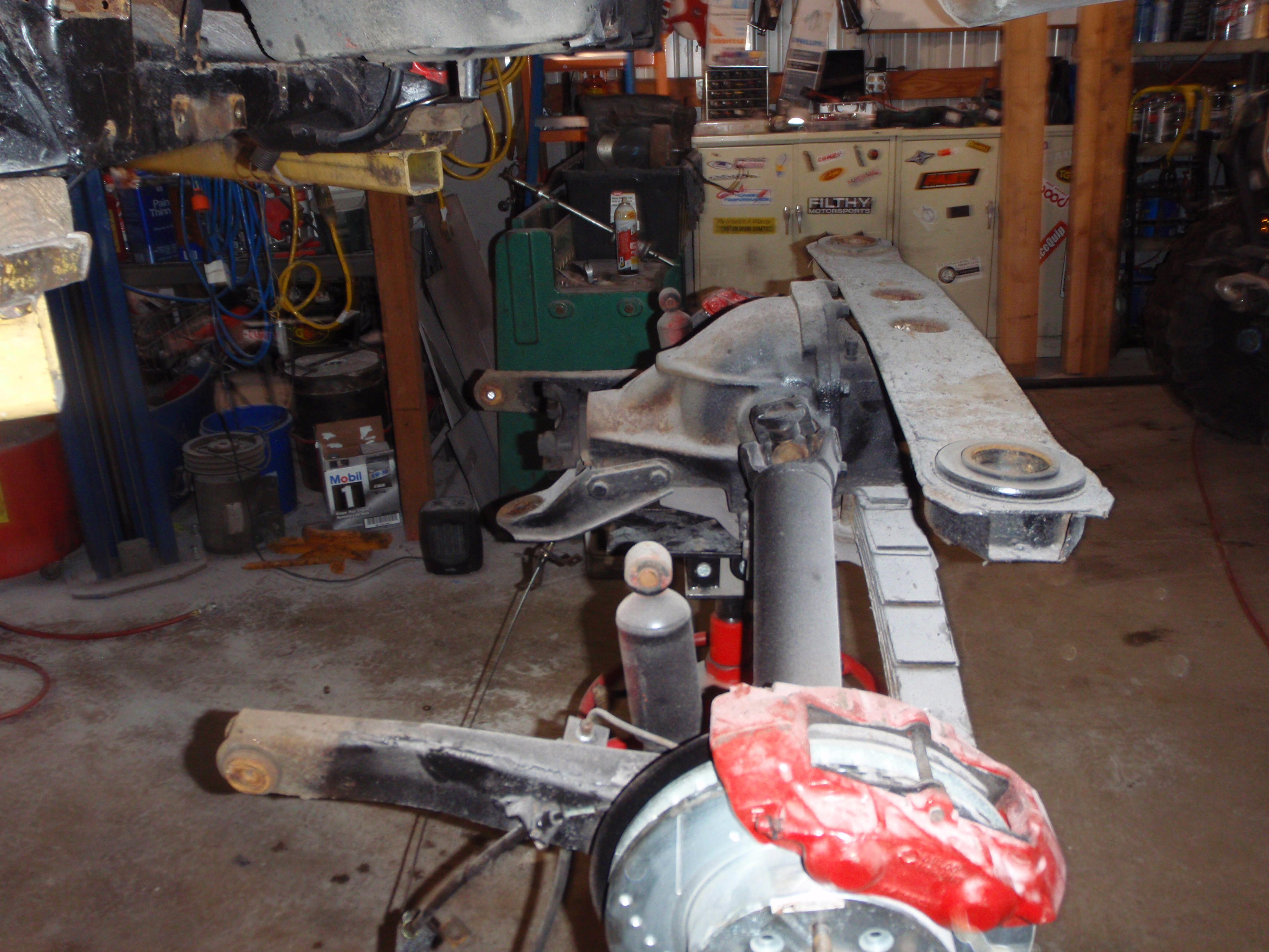
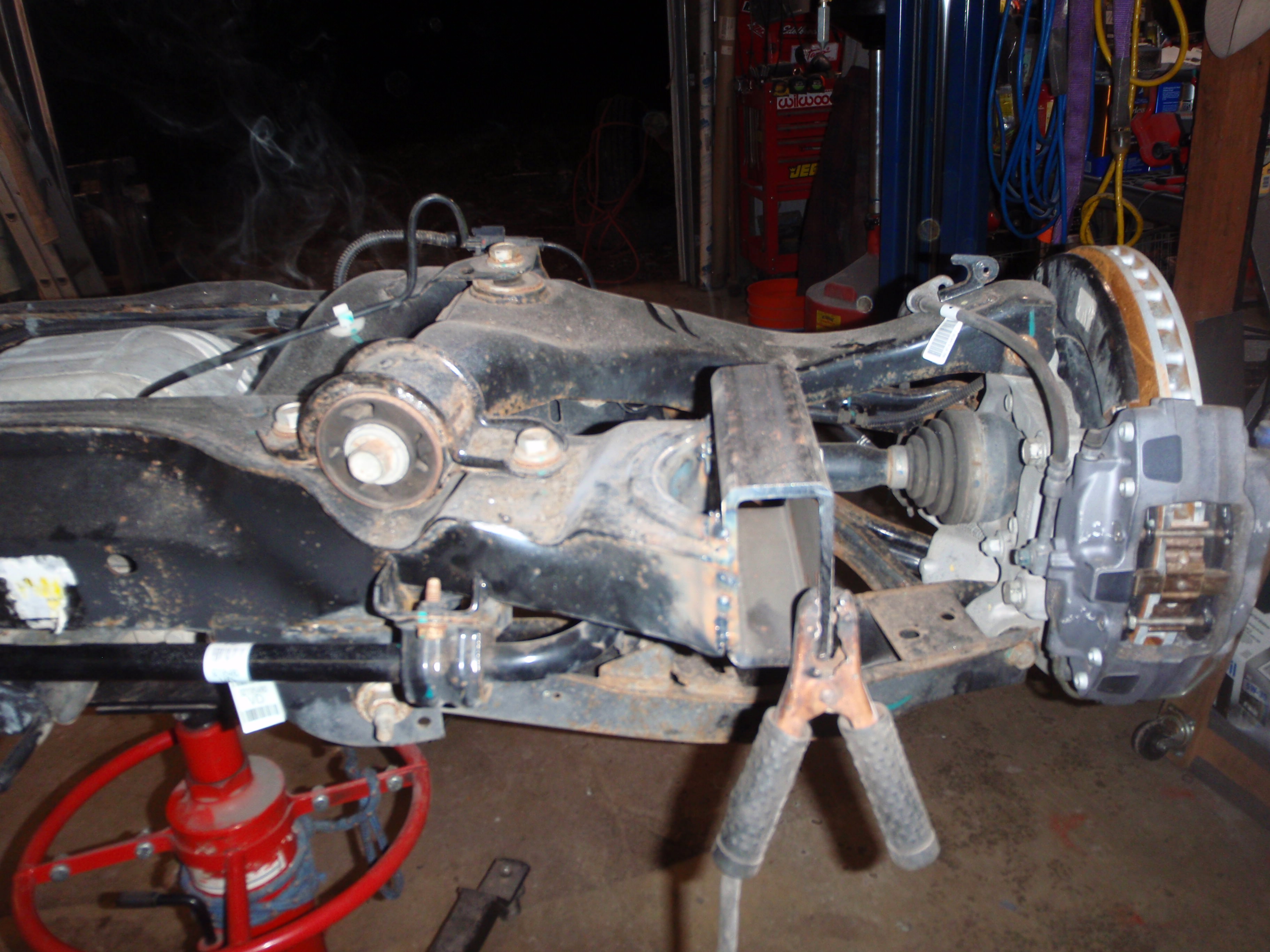
Time to Camaro-ize my Corvette. (I told a friend that I was doing this, his look was aghast at putting a Camaro rear end in a Corvette until I pointed out the year)
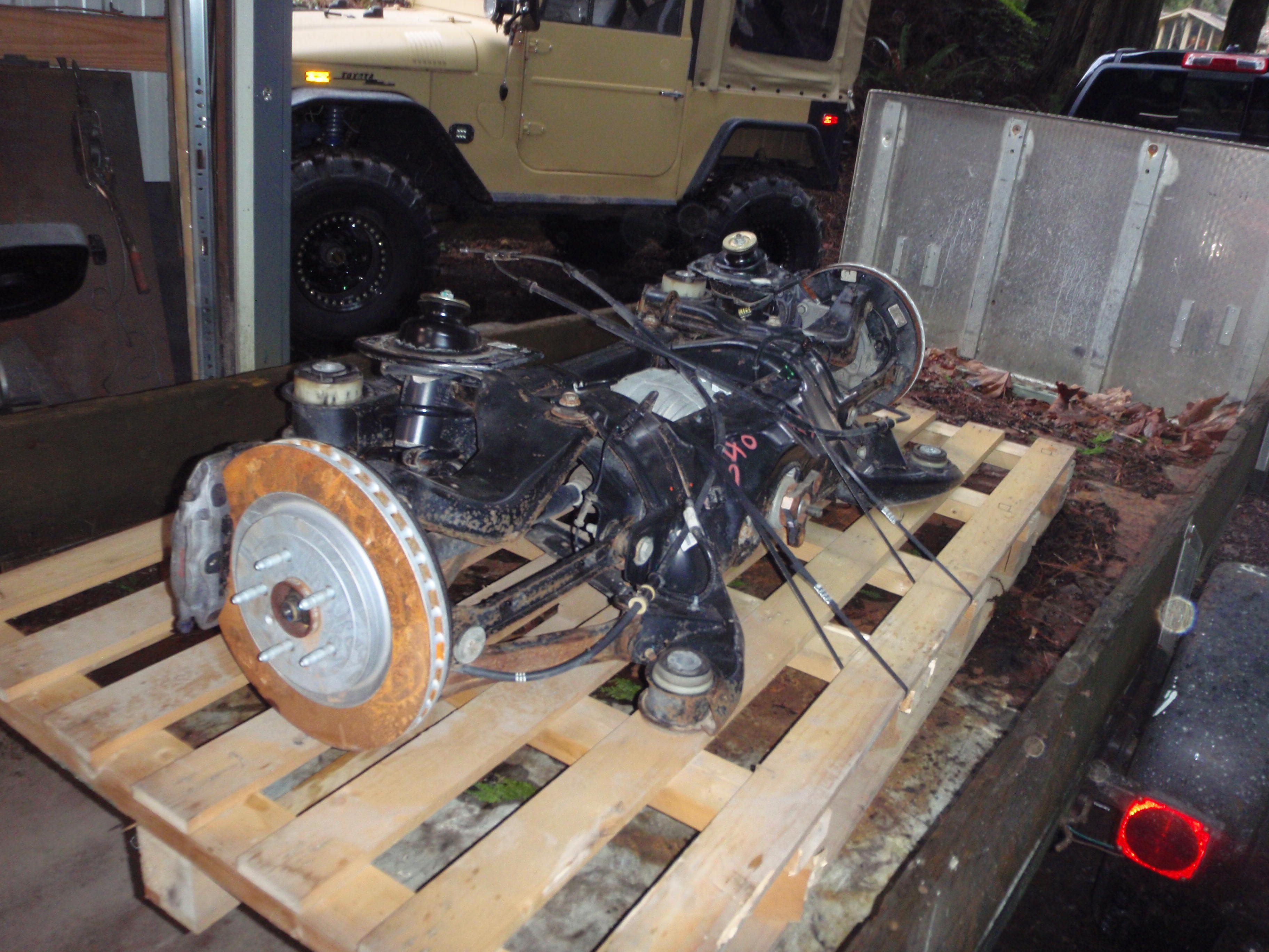
it is 4" wider per side - which corresponds nicely with the 4" flares
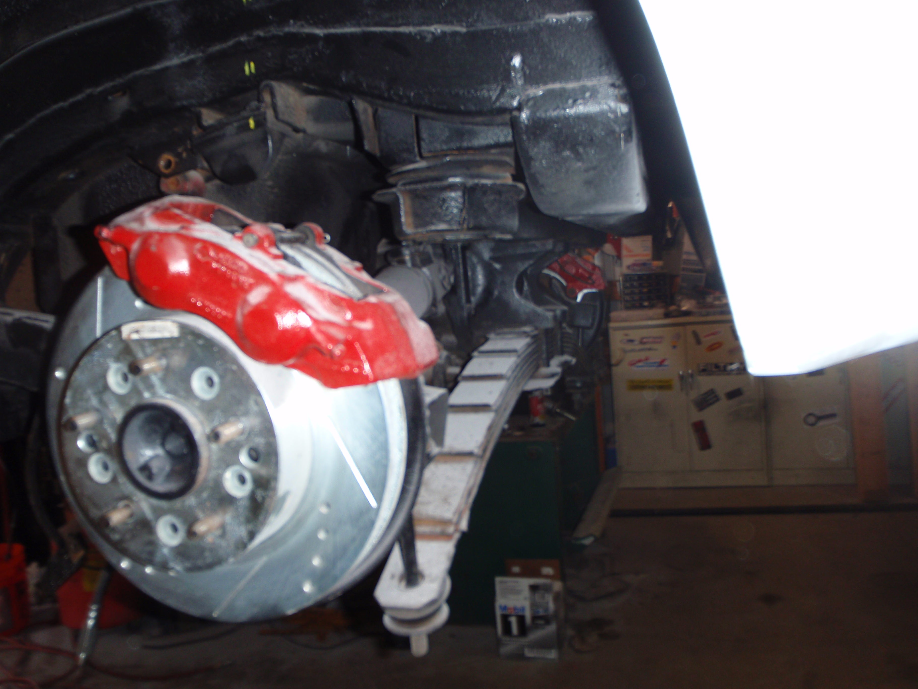
I'm pretty much doomed to upgrading the front because these brakes are large by huge
the basic is this - the front mounts will need a new mount welded to the back of that cross frame. The rear is in line with the frame, but I'm not sure how much of a step it is compared between the two.
another view
there's the difference in track width - I know, deep offset looks cool; center offset handles better
as for suspension. you'll know the moment I do. The Camaro is basically a coil-over, so if I weld a new mount plate - it would work, but I'm not sure how well so we will see - I may use a transverse spring....
it is 4" wider per side - which corresponds nicely with the 4" flares
I'm pretty much doomed to upgrading the front because these brakes are large by huge
the basic is this - the front mounts will need a new mount welded to the back of that cross frame. The rear is in line with the frame, but I'm not sure how much of a step it is compared between the two.
another view
there's the difference in track width - I know, deep offset looks cool; center offset handles better
as for suspension. you'll know the moment I do. The Camaro is basically a coil-over, so if I weld a new mount plate - it would work, but I'm not sure how well so we will see - I may use a transverse spring....
The following users liked this post:
Pegan2261 (11-19-2021)
04-13-2018, 01:40 PM
#154
Melting Slicks
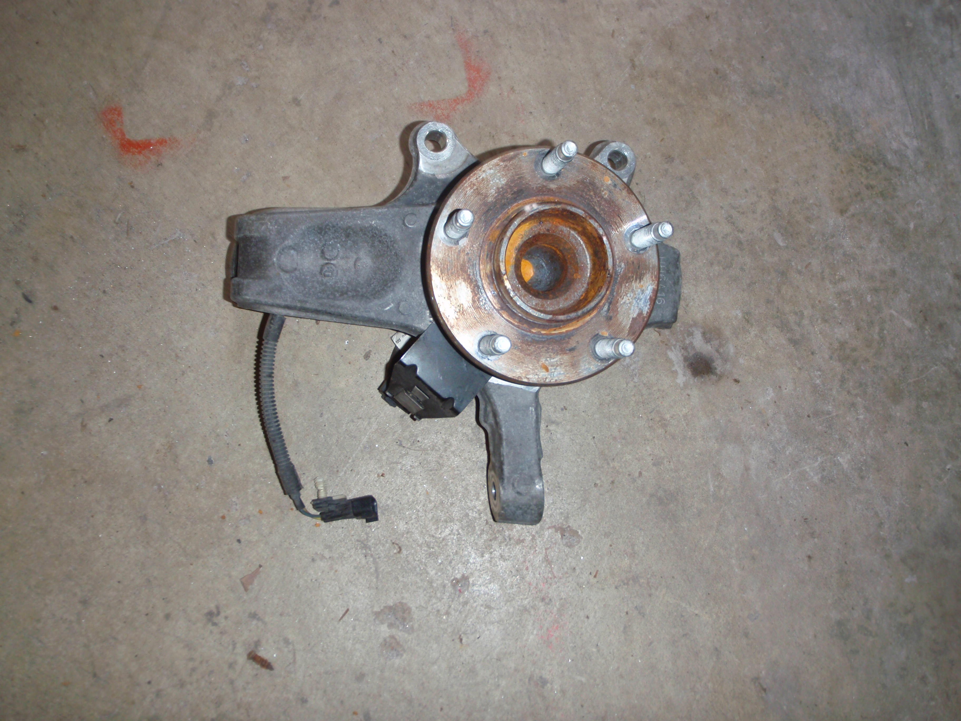
I just ordered the C5 spindles for the front. I haven't, yet, decided whether or not I'll use stock C5 A-arms or build my own.... the fine print is I'm going to switch sides for the spindles then use the stock, C3 steering. If it really needs it, I'll add a borgeson box - but at this moment, I'm not convinced that the work required is worth the end result to make it rack and pinion...
I'm willing to listen to opinions but your opinions should have "and when I installed ___, this is what I found" ... I can google too, so I don't need rehashed google opinions (sorry, but it seems I more then my share of checkbook racers, so in an attempt to maintain peace, I provide some warning )
)
I'm willing to listen to opinions but your opinions should have "and when I installed ___, this is what I found" ... I can google too, so I don't need rehashed google opinions (sorry, but it seems I more then my share of checkbook racers, so in an attempt to maintain peace, I provide some warning
)
04-15-2018, 09:33 PM
#155
Melting Slicks
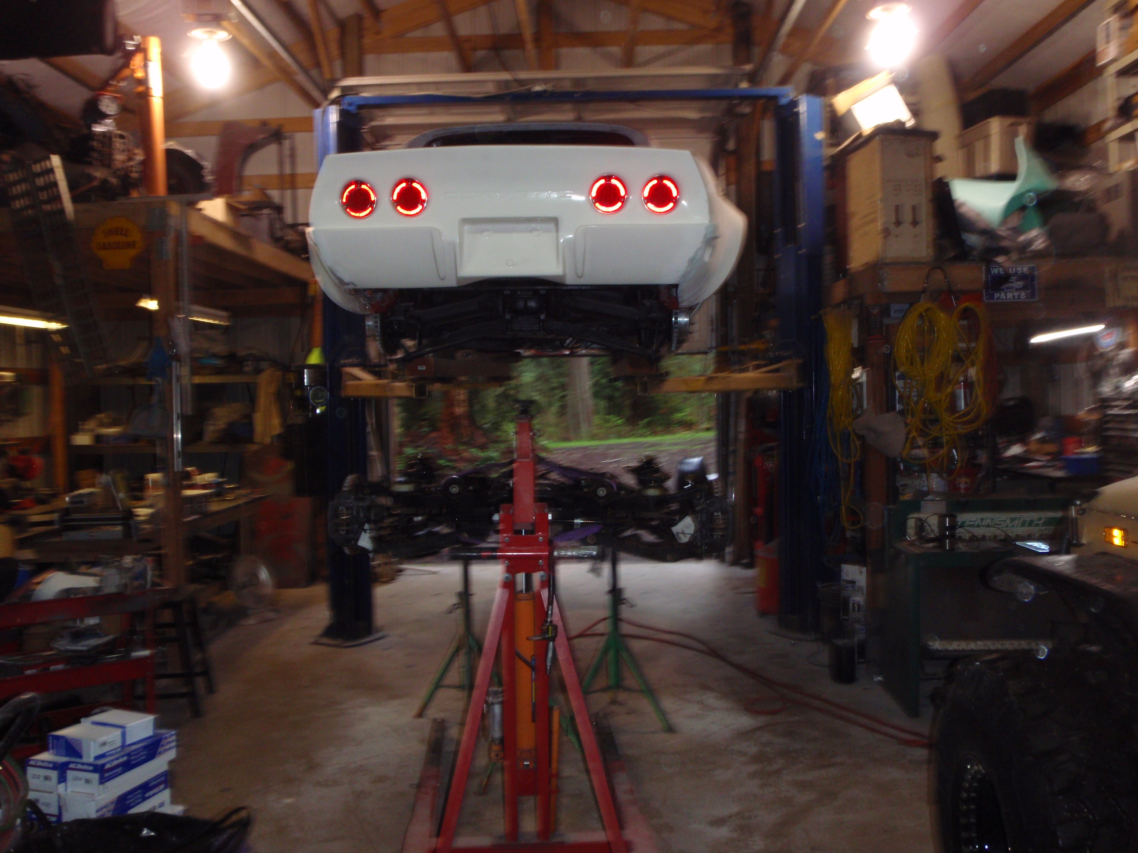
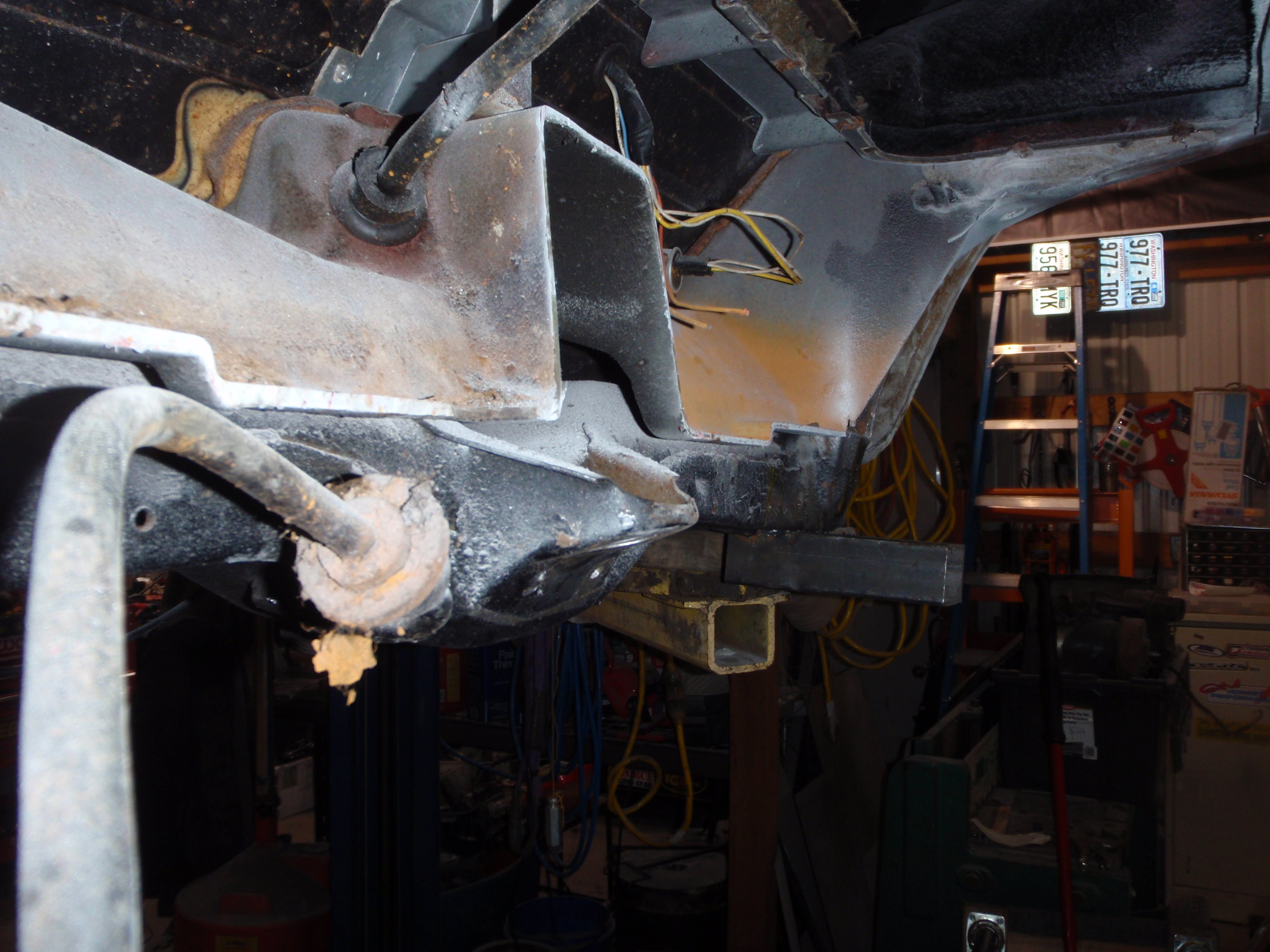
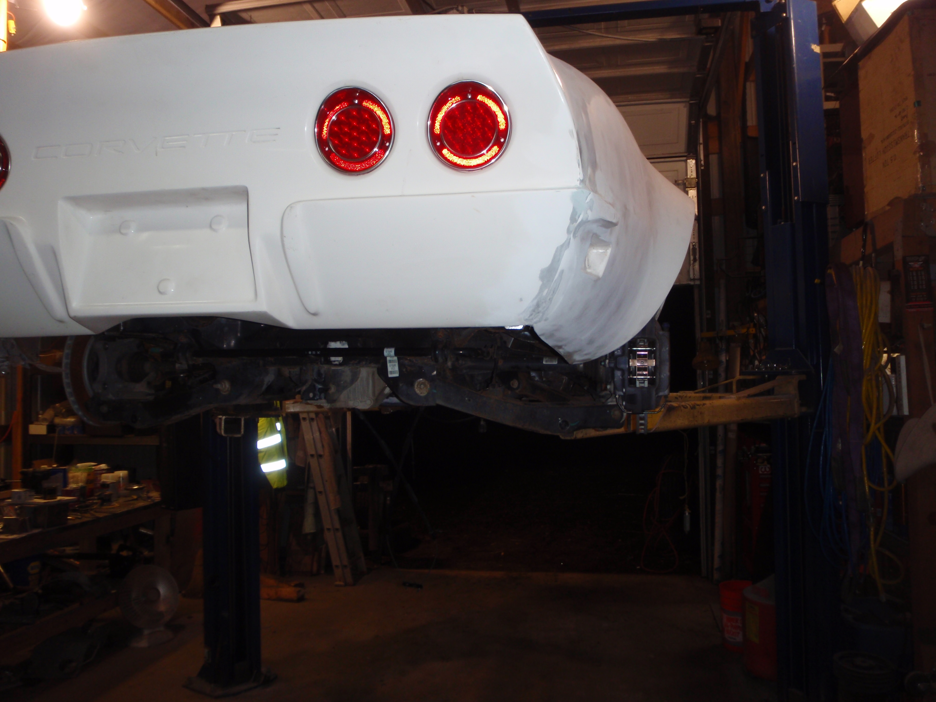
I can only imagine the aghast horror the ones who prefer restored cars would see in the following pictures. For that reason, the following is rated DON'T LOOK for NCRS contestants, judges, their wives or their serfs.
okay, again, NSFNCRS
we good? good
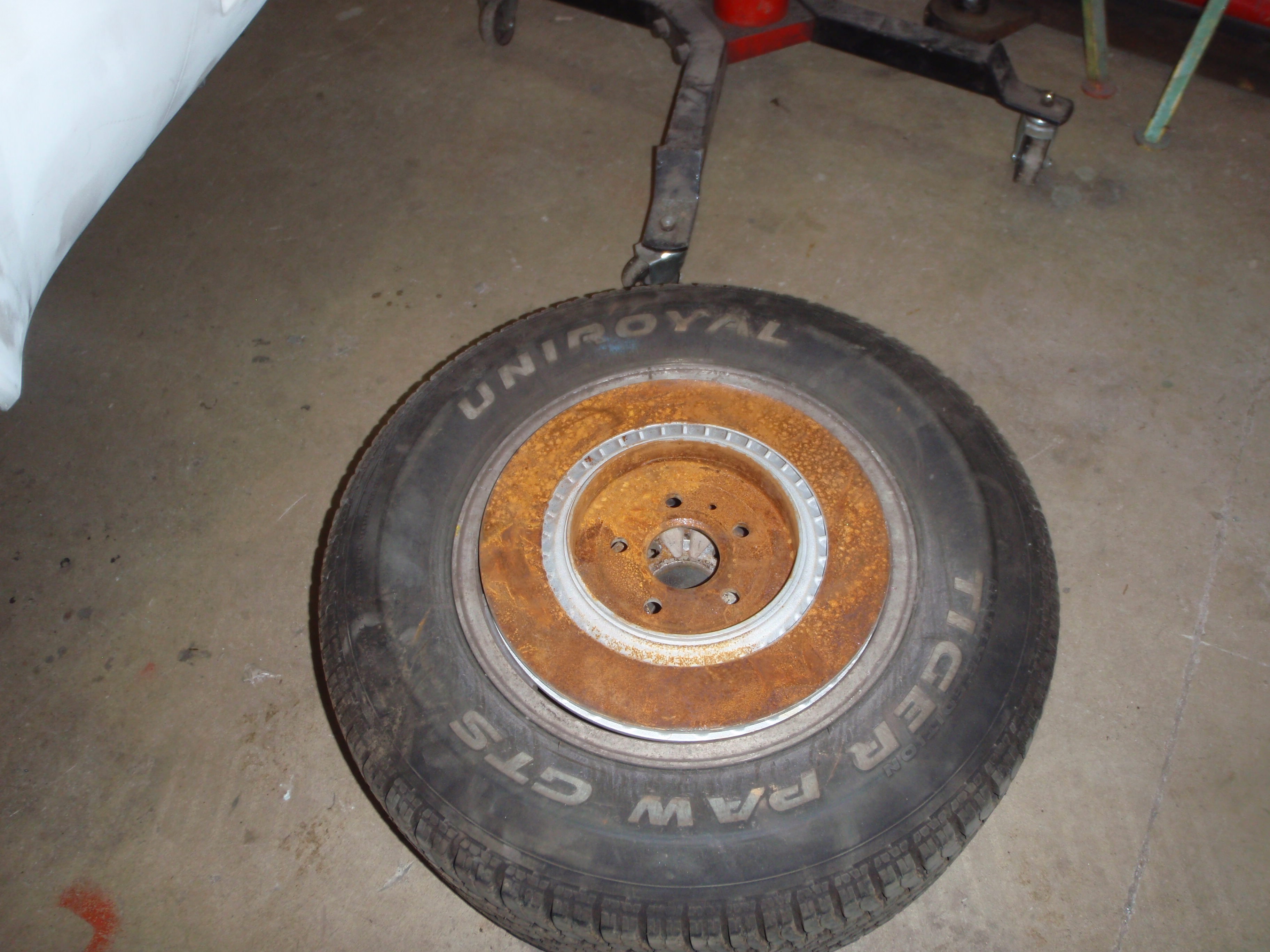
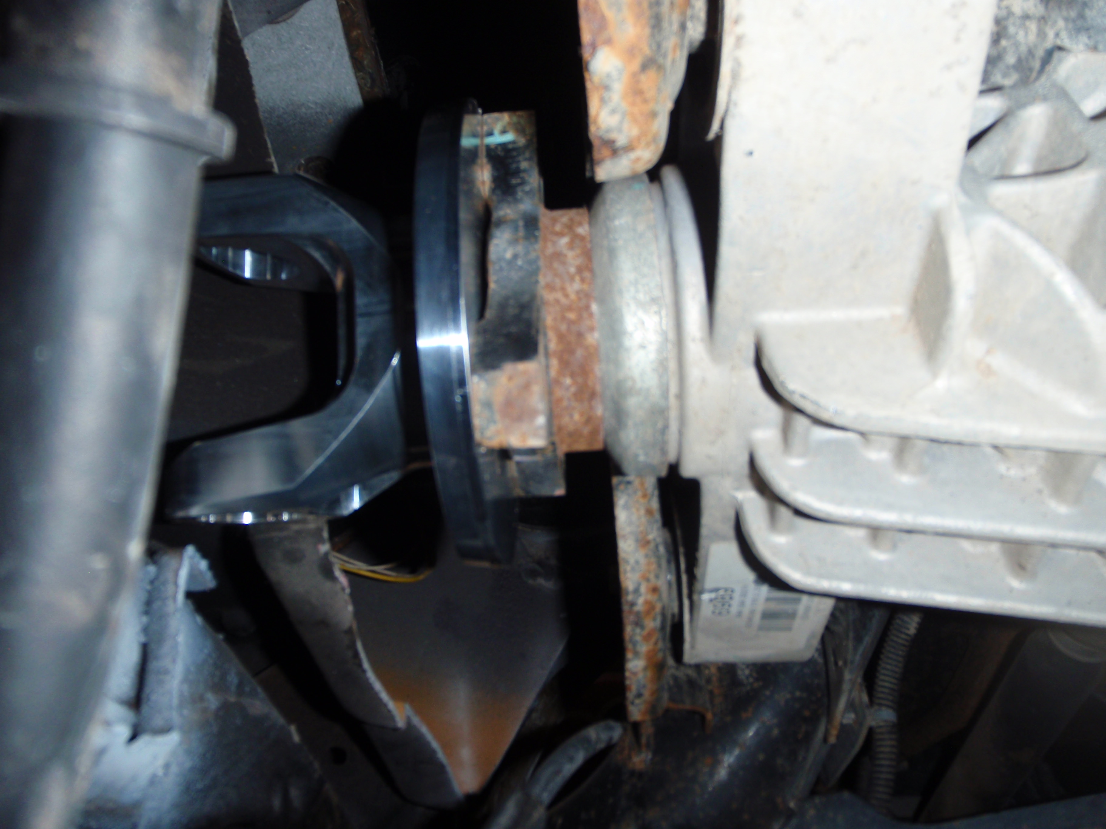
this, needs to fall out
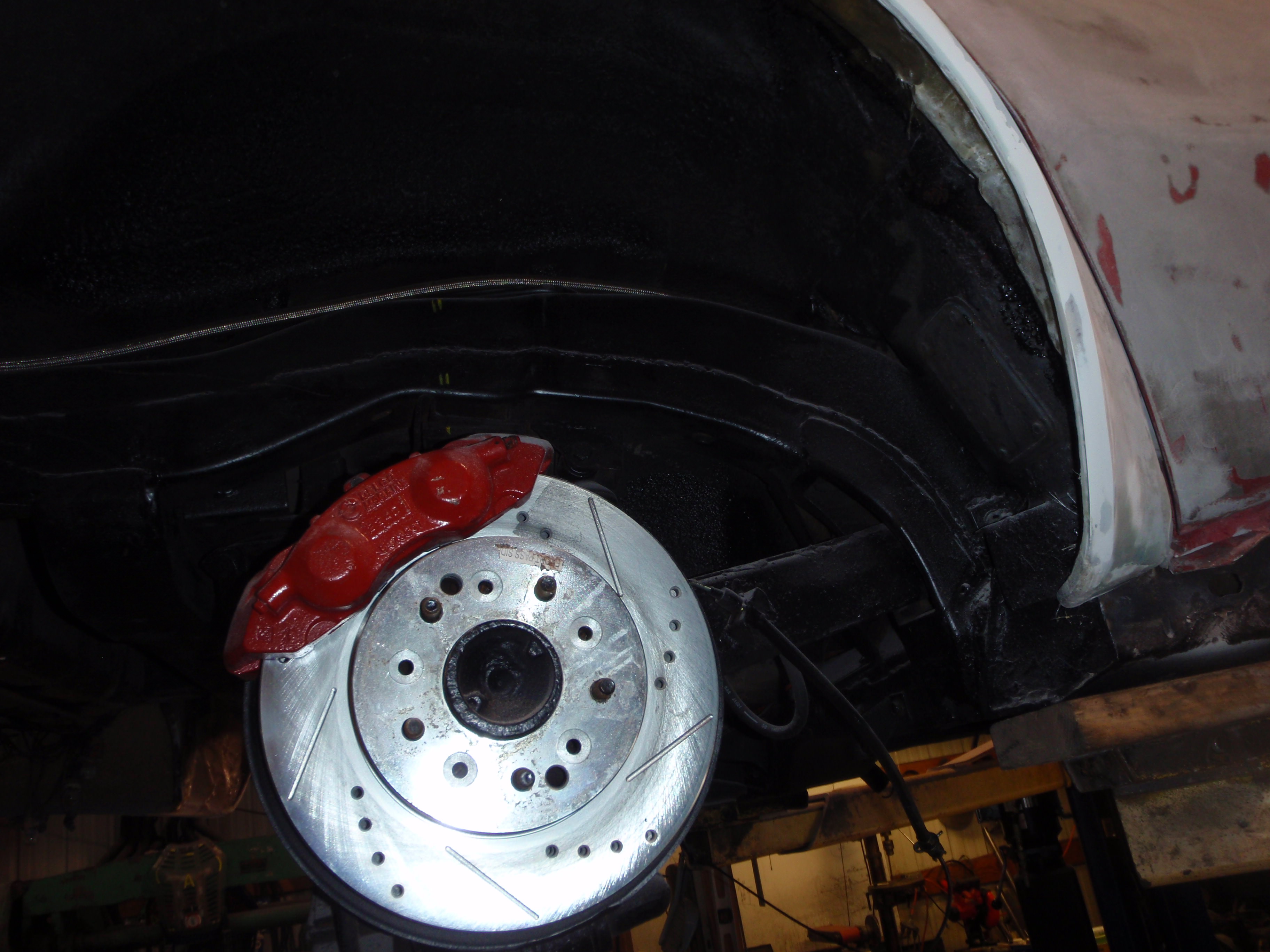
nice, new brakes... that will never be used
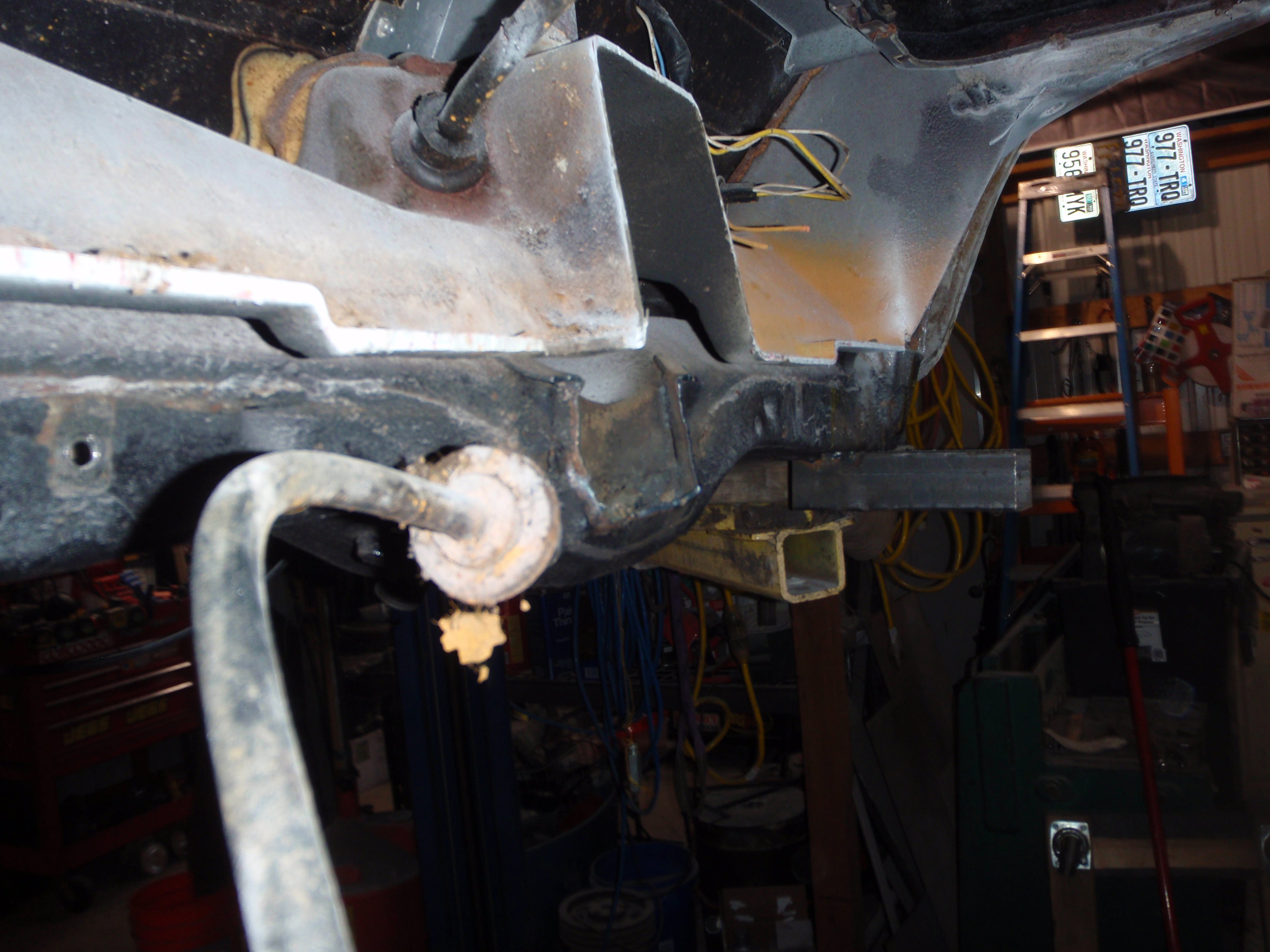
today's tutorial.
How to remove trailing arms in 2 hours or less
first, loosen the outside nut and take all the cotter pins out (including the one that holds the shims in place)
then pry out the outer-most shims (it actually is pretty easy)
then cut the bolt on the outside
now move to the inside bolt, cut the head off
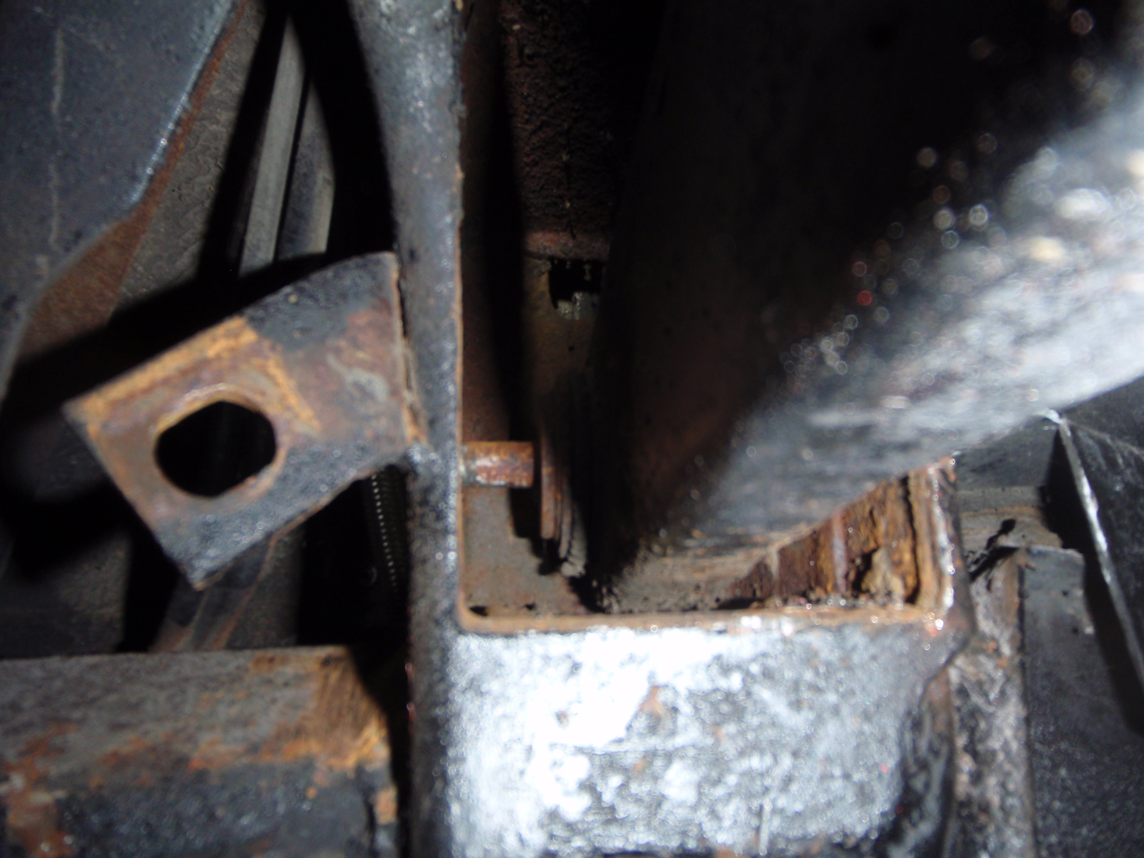
knock the head off with a air chisel
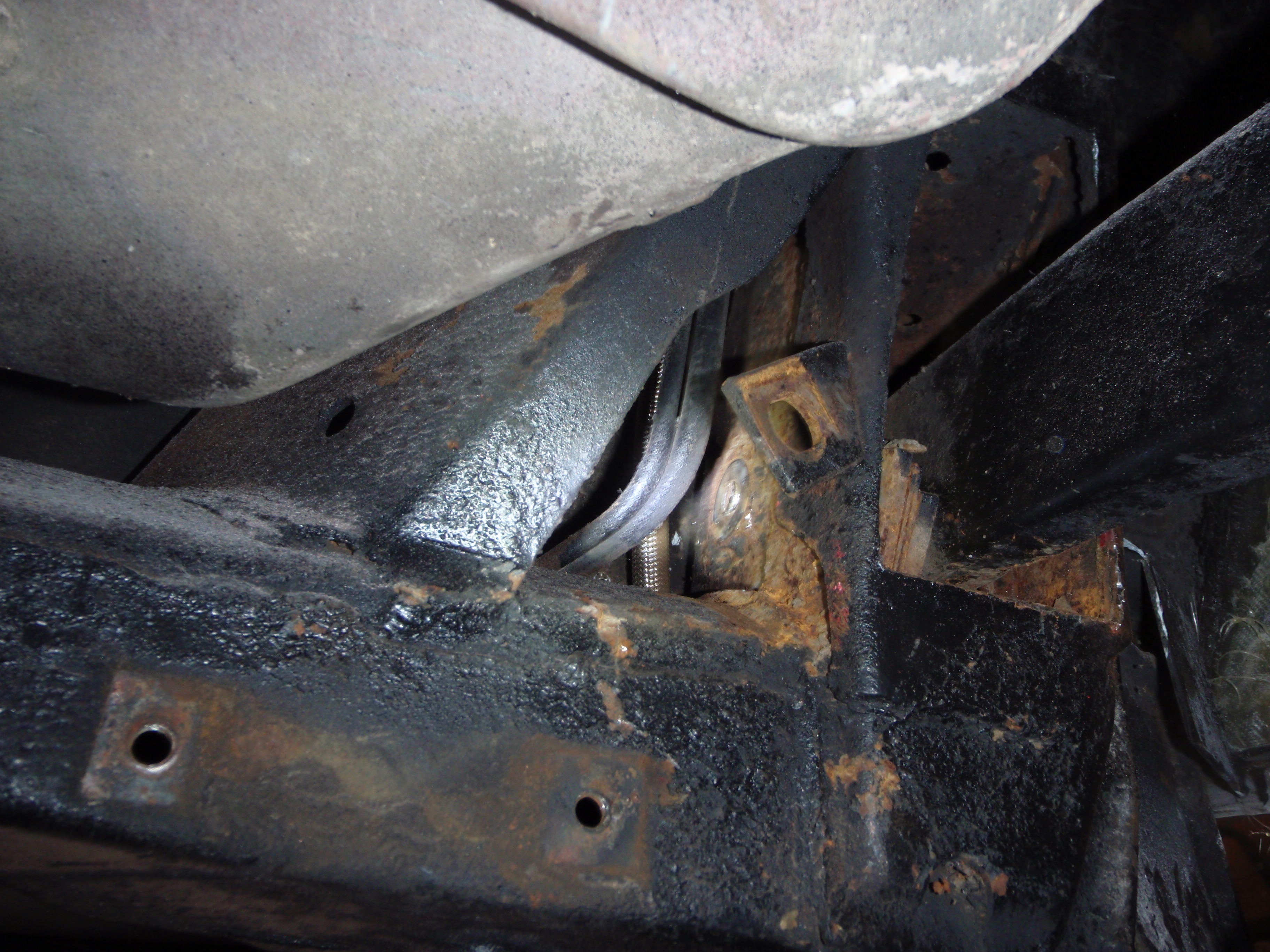
pry in, cut the bolt on the inside
remove.... this took - to this point, 3 hours.
If anyone needs a 3.36 gear rear.... it's for sale.
it seriously took more time to get the tools out and ready, I went through 2 blades - mostly because you're only using the very end.... I used them later.... see below
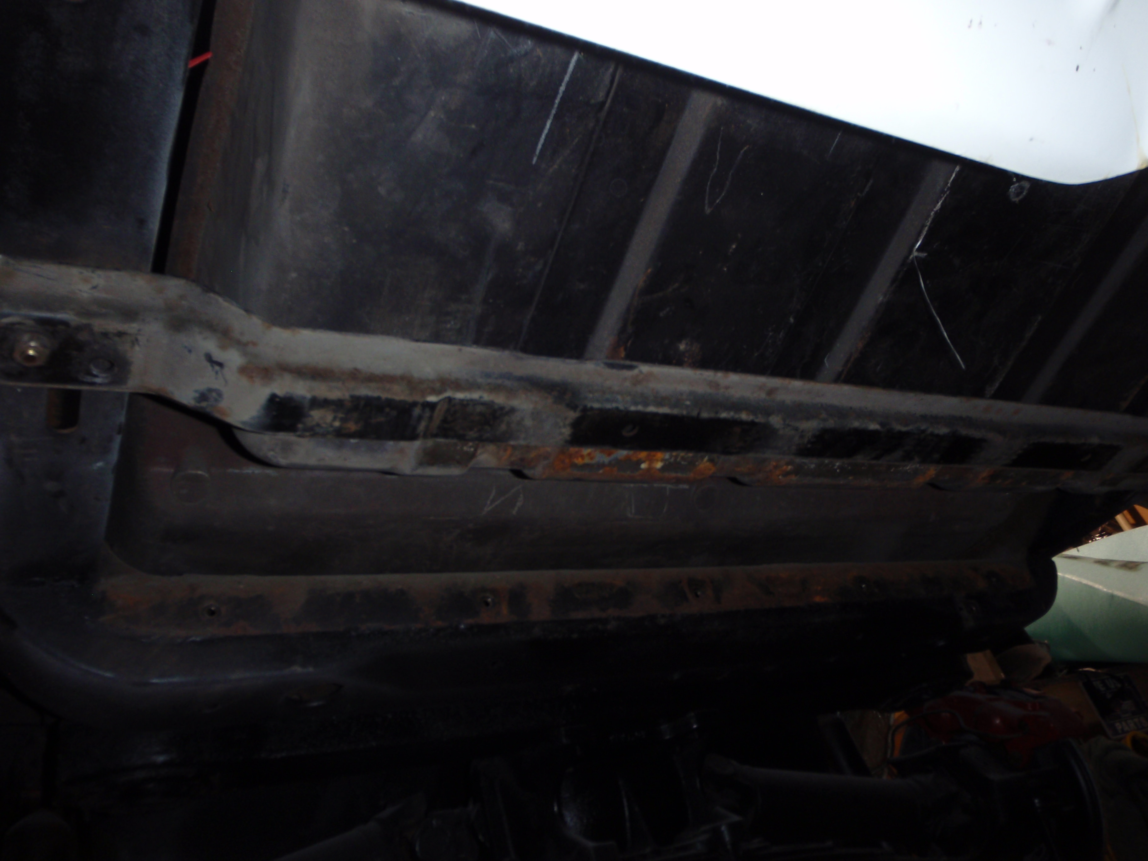
first fit without obstruction... well, the well boxes are obstructing
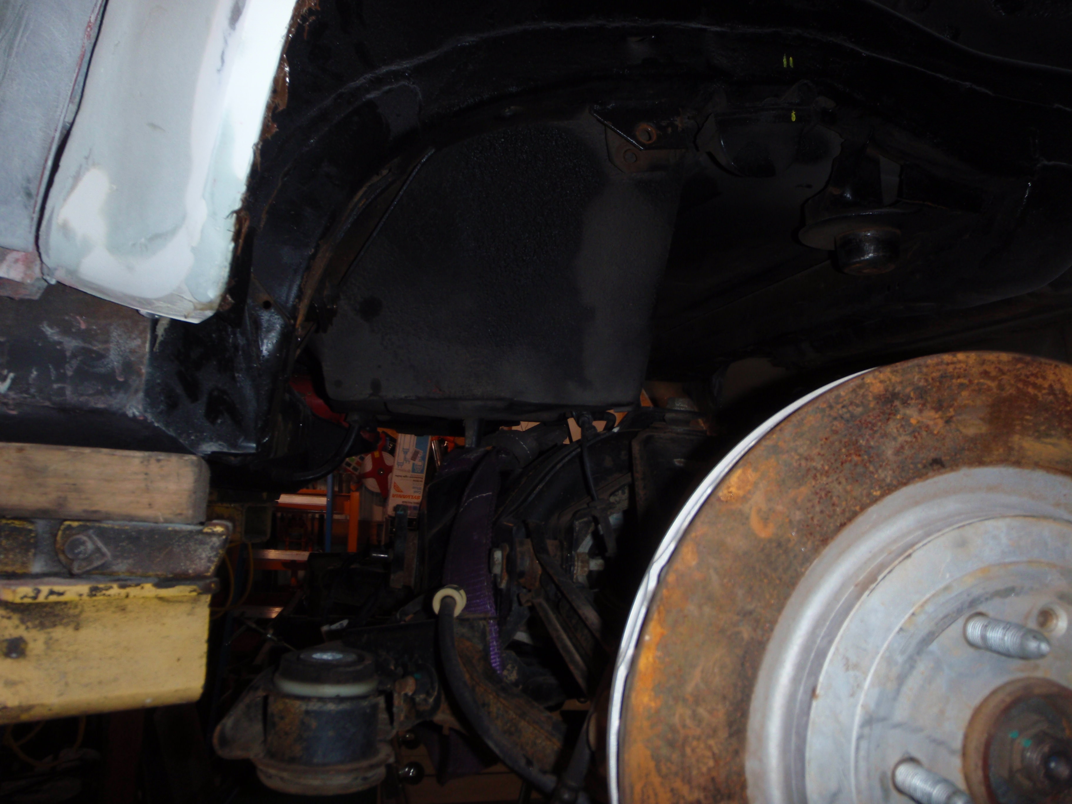
beside the boxes, problem 2 is apparent in this picture too
better seen here
I'll build a battery boxy for behind the passenger seat.... cap the rest
in all of this, getting windows tinted.... I hope he does a good job because I know hundreds of people who'll use him if he is
tinting booth
a few cars
but here's where I'm at now
I'm considering simply welding the entire structure in place.... it would be stronger and eliminate some bushings... as far as I can see, all the bolts would be accessible - which is why I have a production pause going on....
I think it looks pretty cool
I suspect I can use stock C7 wheels
okay, again, NSFNCRS
we good? good
this, needs to fall out
nice, new brakes... that will never be used
today's tutorial.
How to remove trailing arms in 2 hours or less
first, loosen the outside nut and take all the cotter pins out (including the one that holds the shims in place)
then pry out the outer-most shims (it actually is pretty easy)
then cut the bolt on the outside
now move to the inside bolt, cut the head off
knock the head off with a air chisel
pry in, cut the bolt on the inside
remove.... this took - to this point, 3 hours.
If anyone needs a 3.36 gear rear.... it's for sale.
it seriously took more time to get the tools out and ready, I went through 2 blades - mostly because you're only using the very end.... I used them later.... see below
first fit without obstruction... well, the well boxes are obstructing
beside the boxes, problem 2 is apparent in this picture too
better seen here
I'll build a battery boxy for behind the passenger seat.... cap the rest
in all of this, getting windows tinted.... I hope he does a good job because I know hundreds of people who'll use him if he is
tinting booth
a few cars
but here's where I'm at now
I'm considering simply welding the entire structure in place.... it would be stronger and eliminate some bushings... as far as I can see, all the bolts would be accessible - which is why I have a production pause going on....
I think it looks pretty cool
I suspect I can use stock C7 wheels
The following users liked this post:
SuperBuickGuy (04-16-2018)
 04-18-2018, 12:24 AM
#158
Melting Slicks
and lots of pictures you'll get
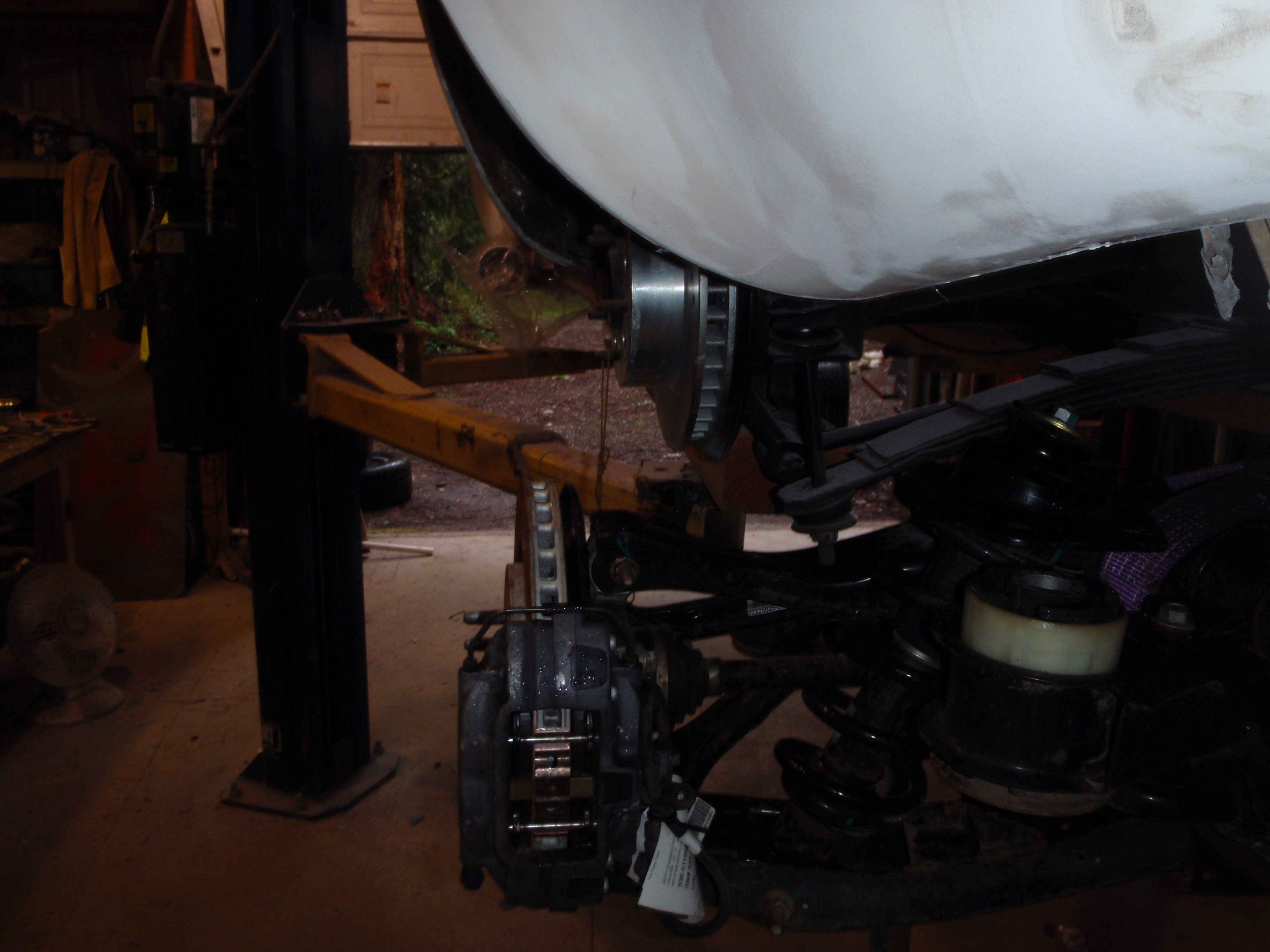
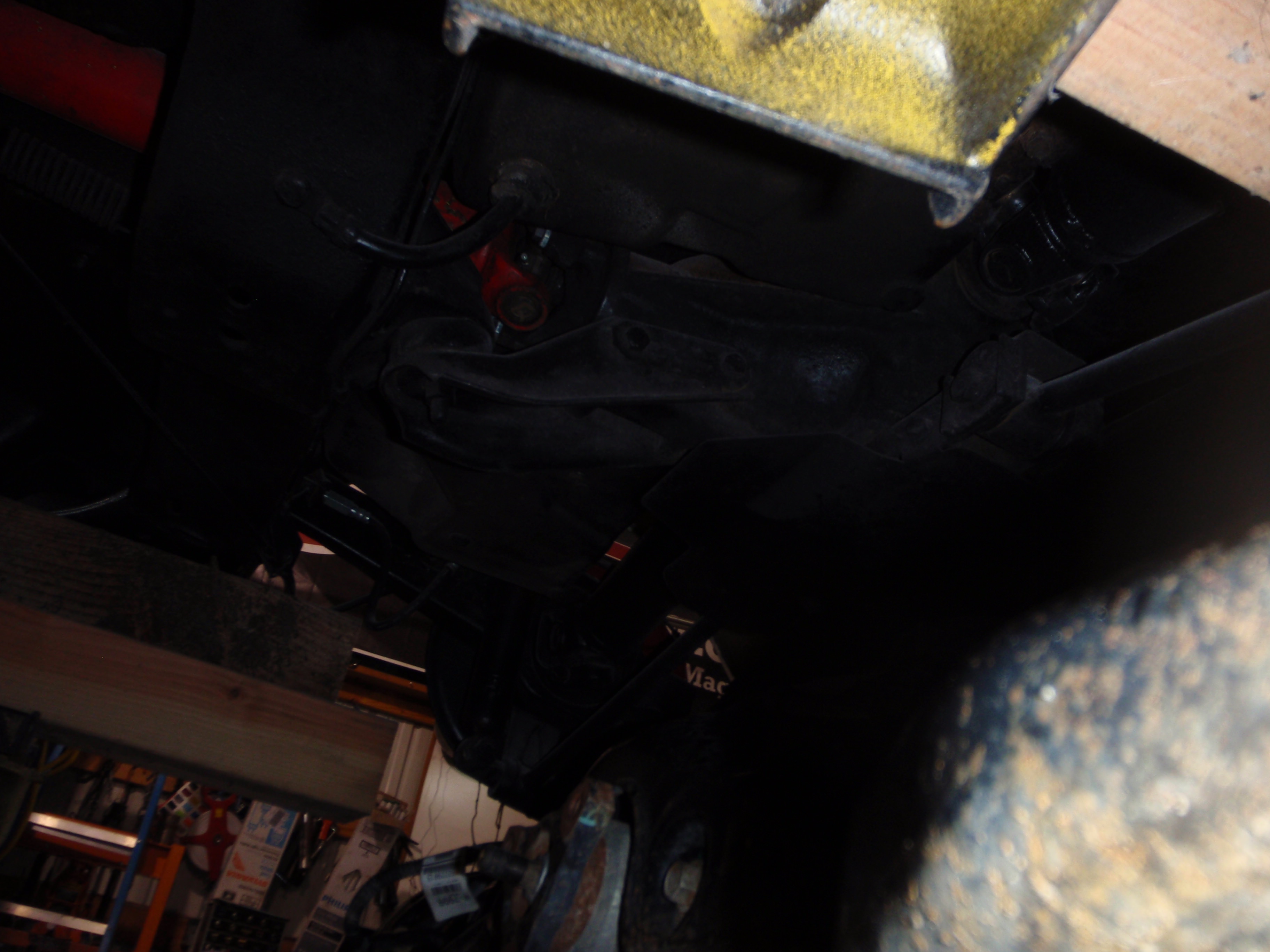
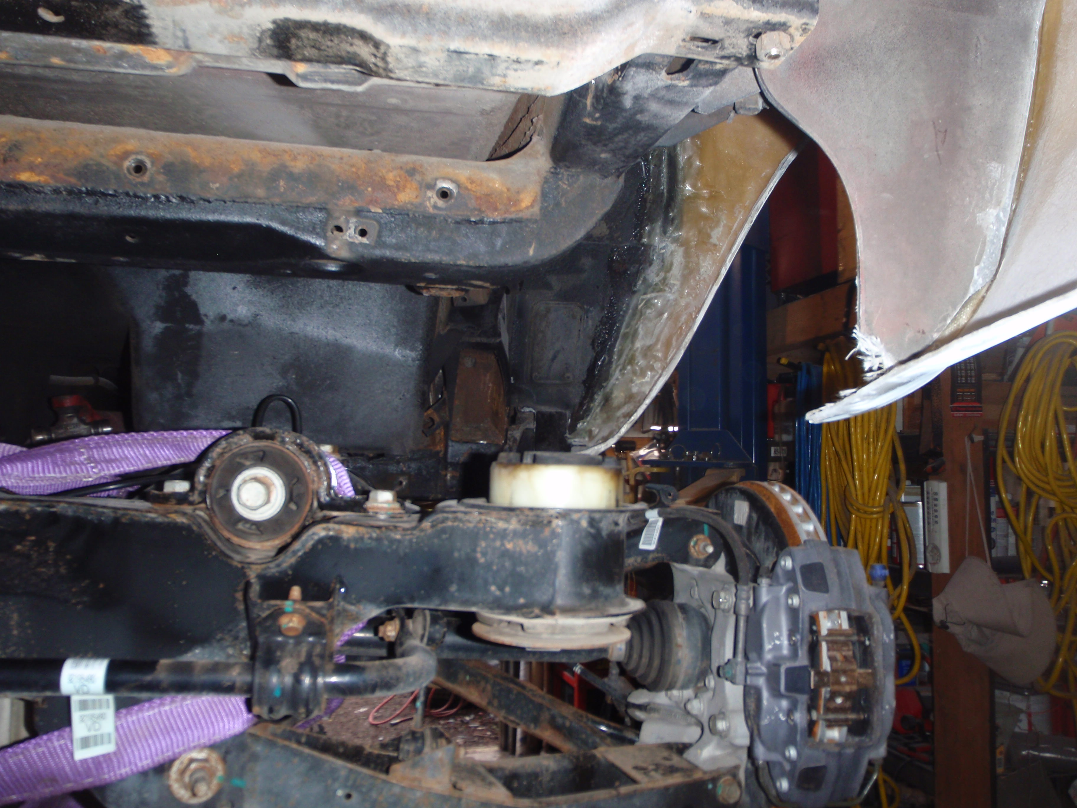
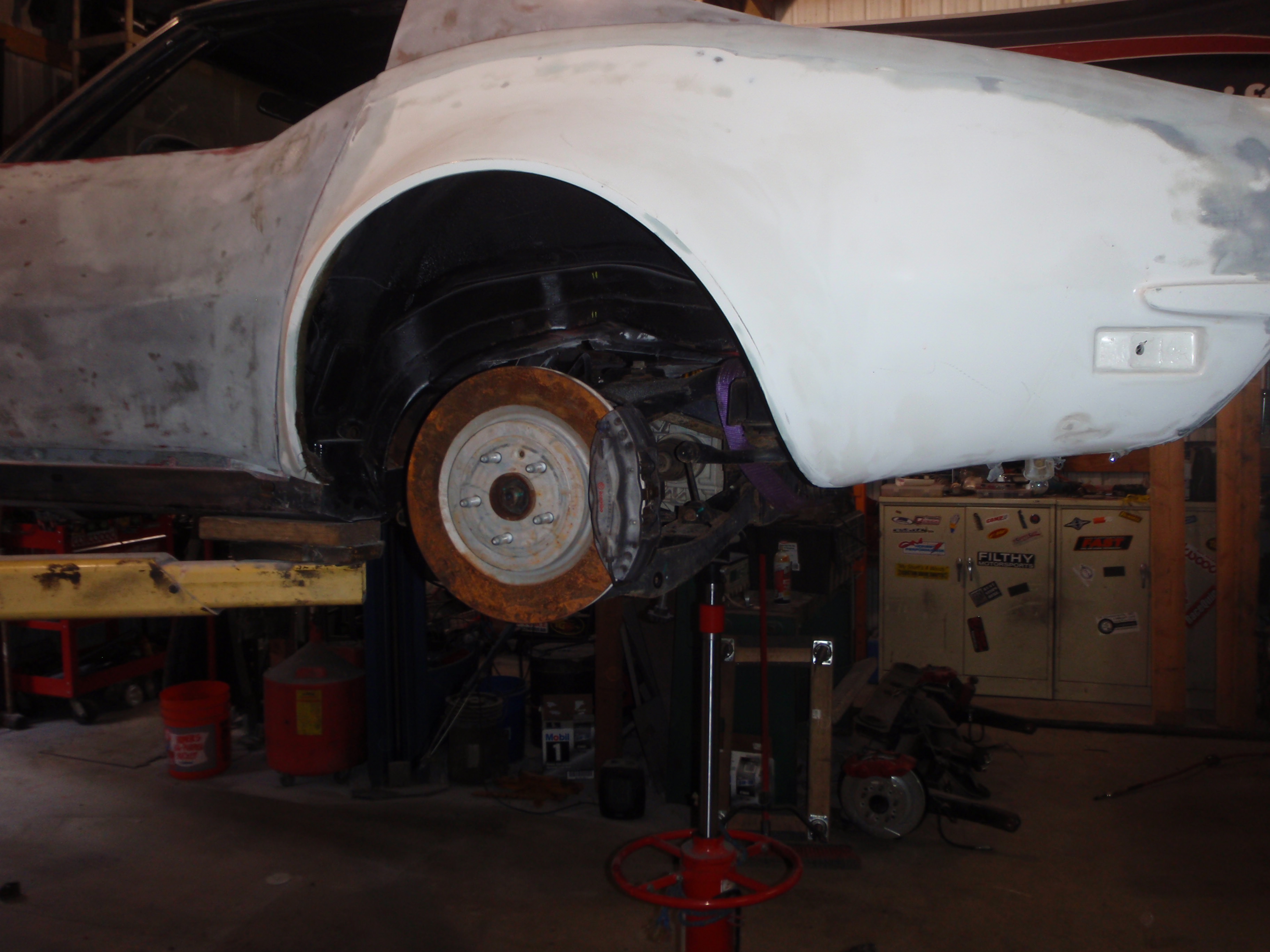
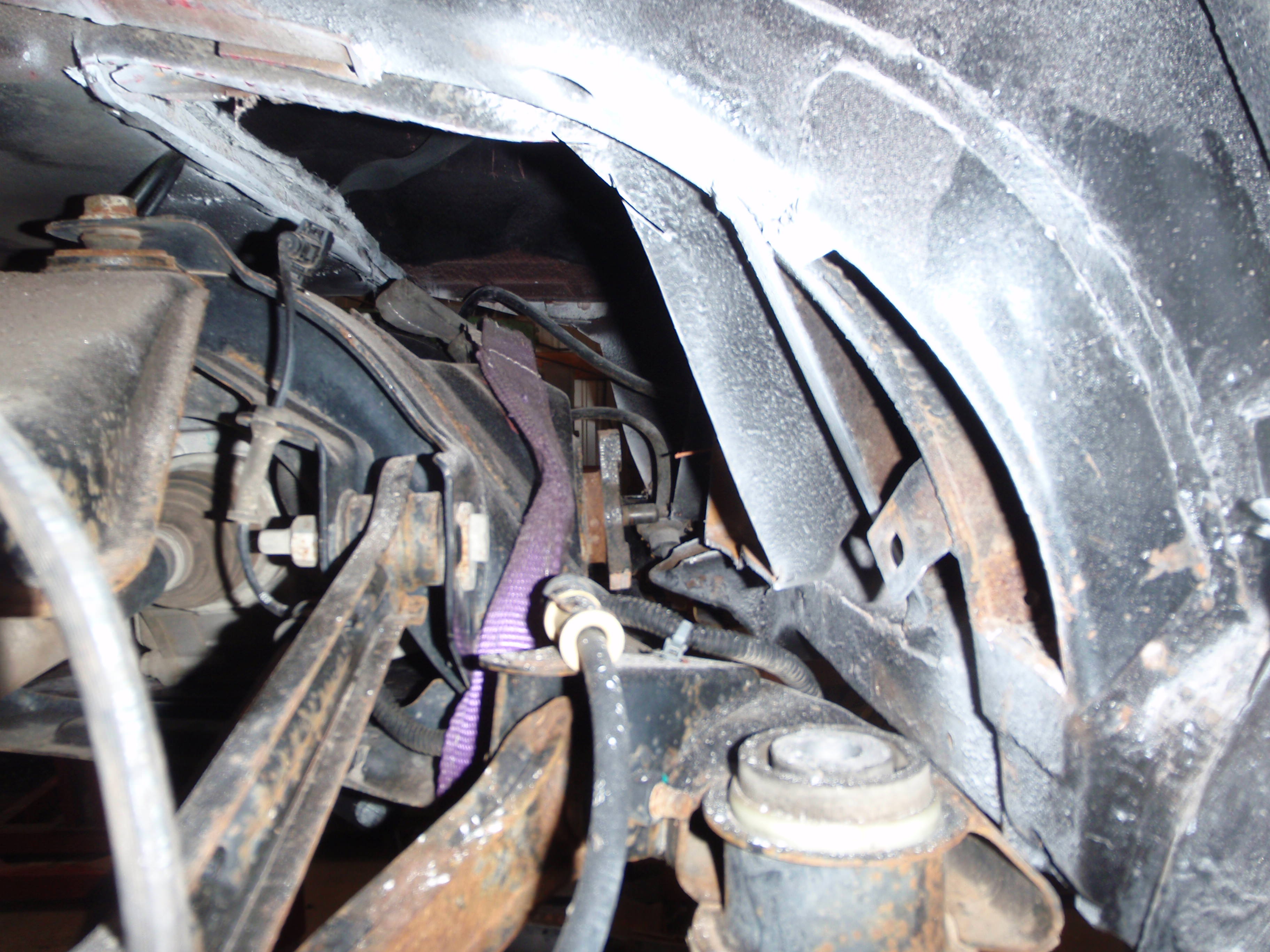
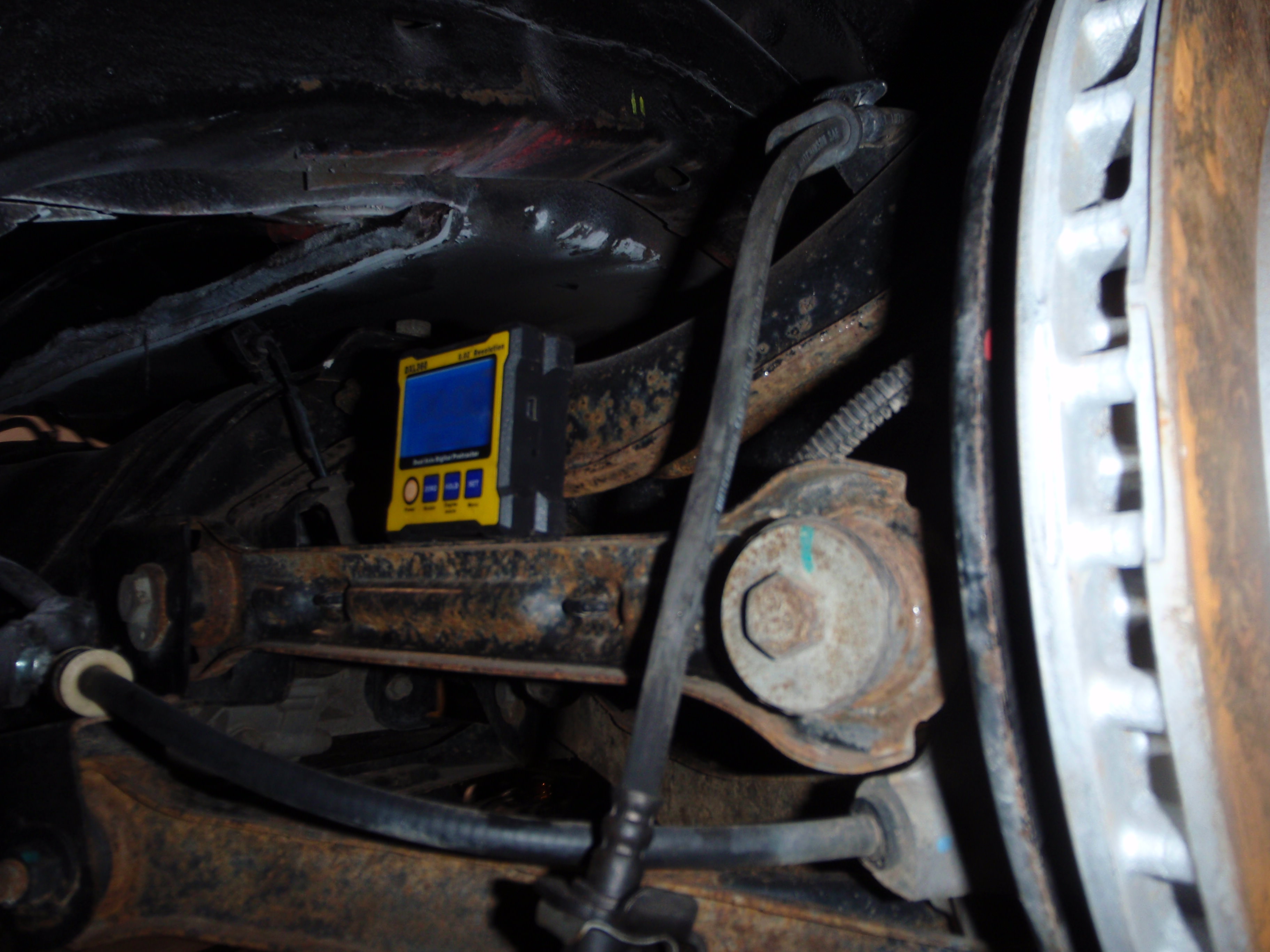
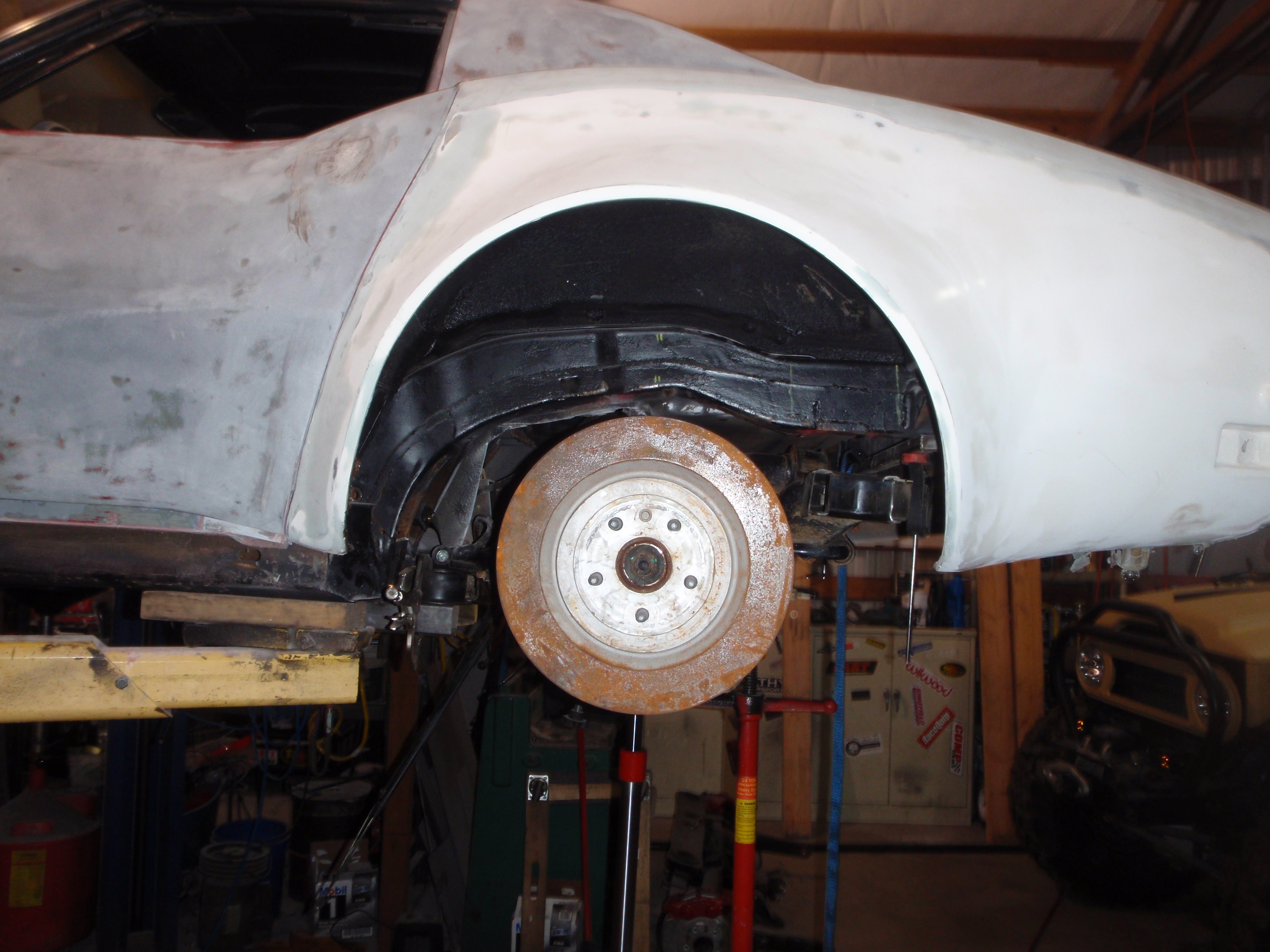
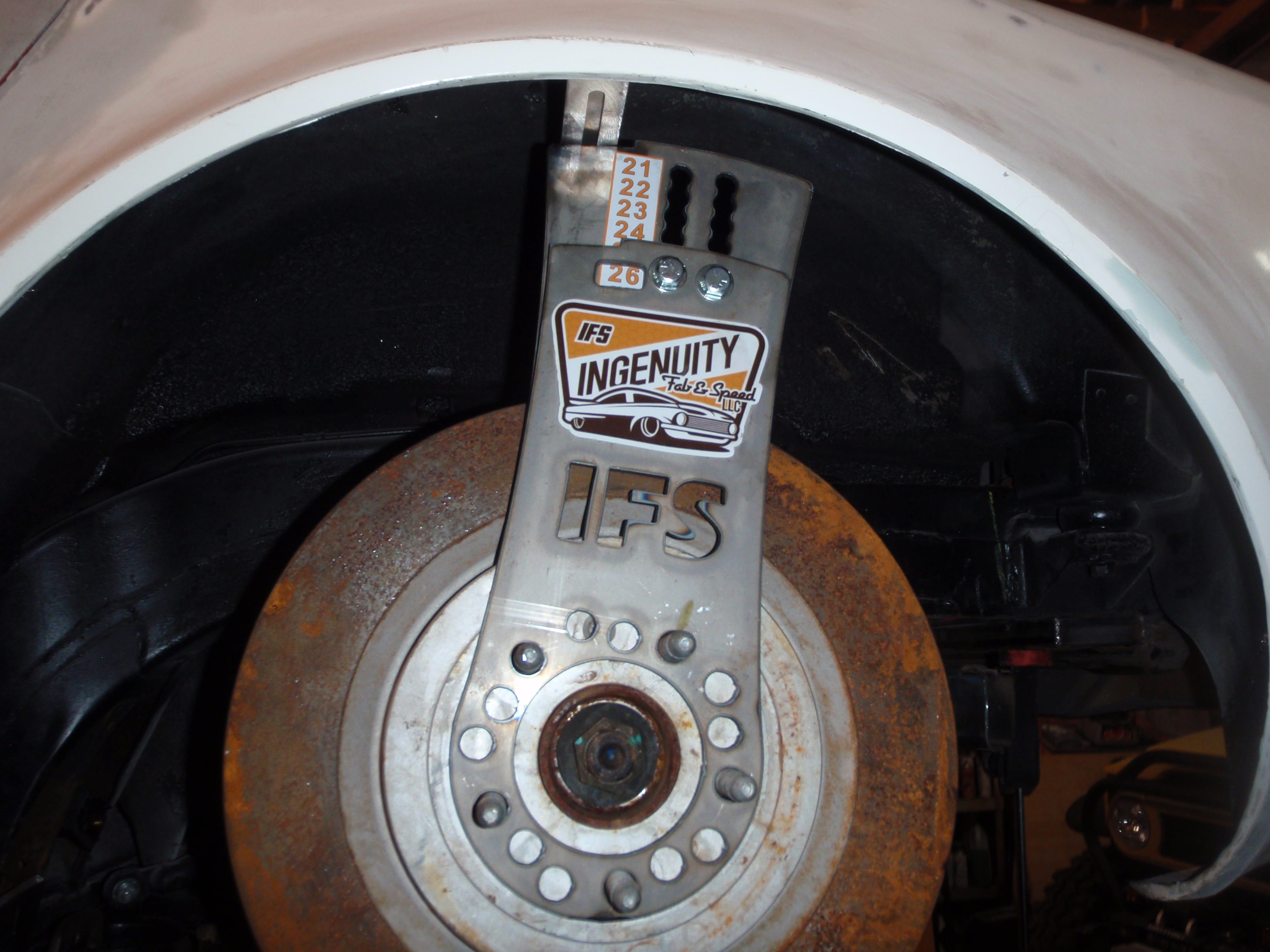
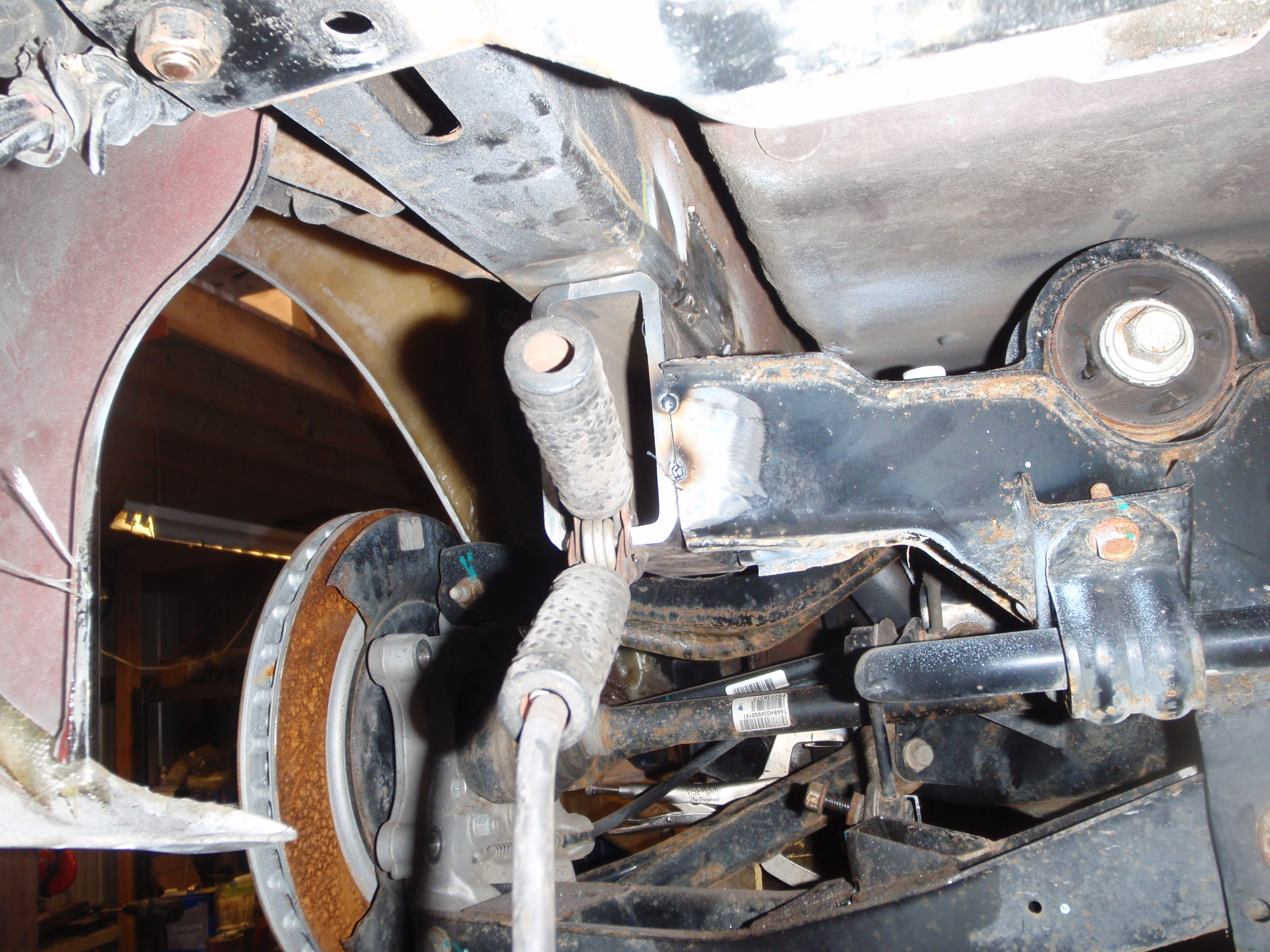
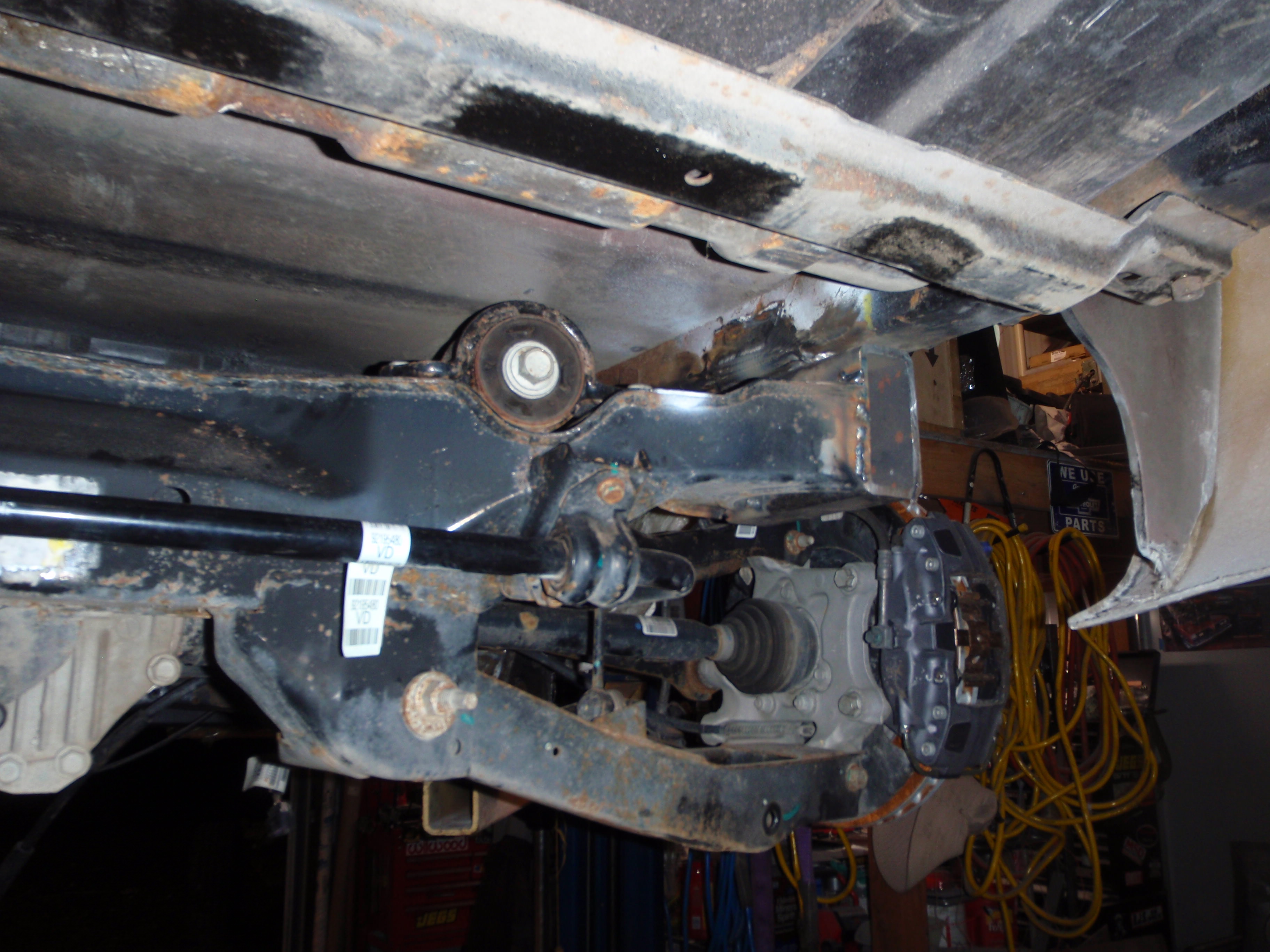
So this set of pictures is after disconnecting the sway bar and seeing how close to perpendicular the axle is moving. I think, this is just a guess, but I think the mounts would be about 1 1/2 below the cross bar on the C3... no big deal to cut and re-shape, but that's my eduguess as to where this is going to end up
pictures
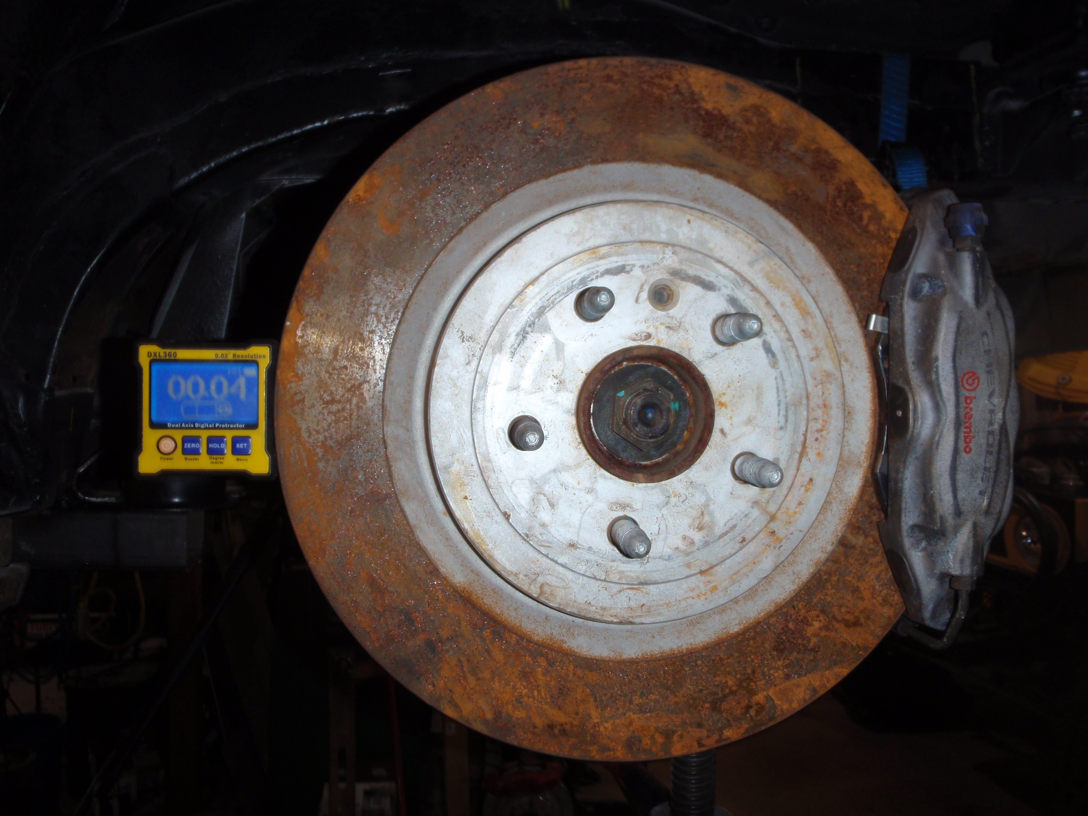
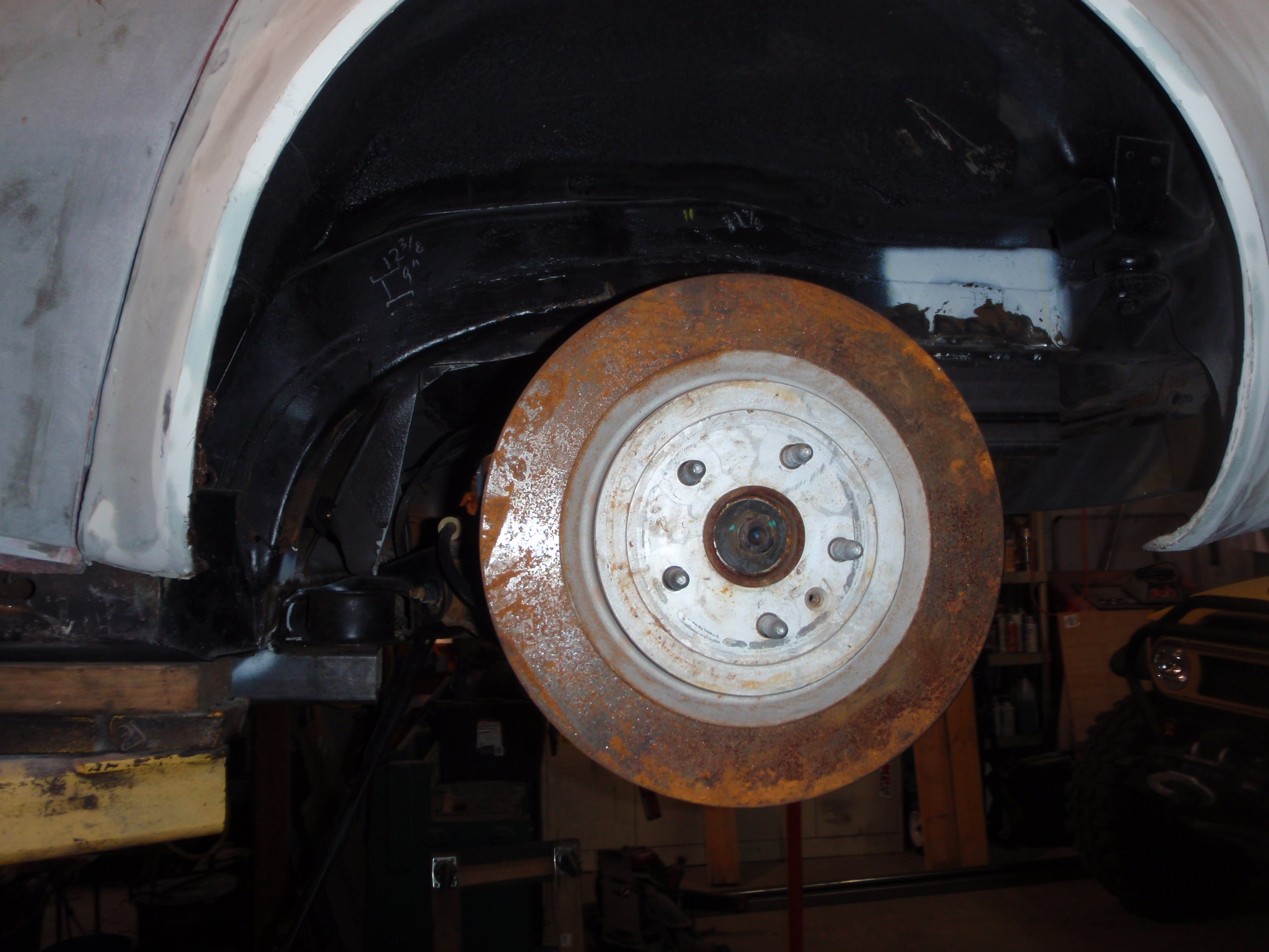
zero(ish) at full drop
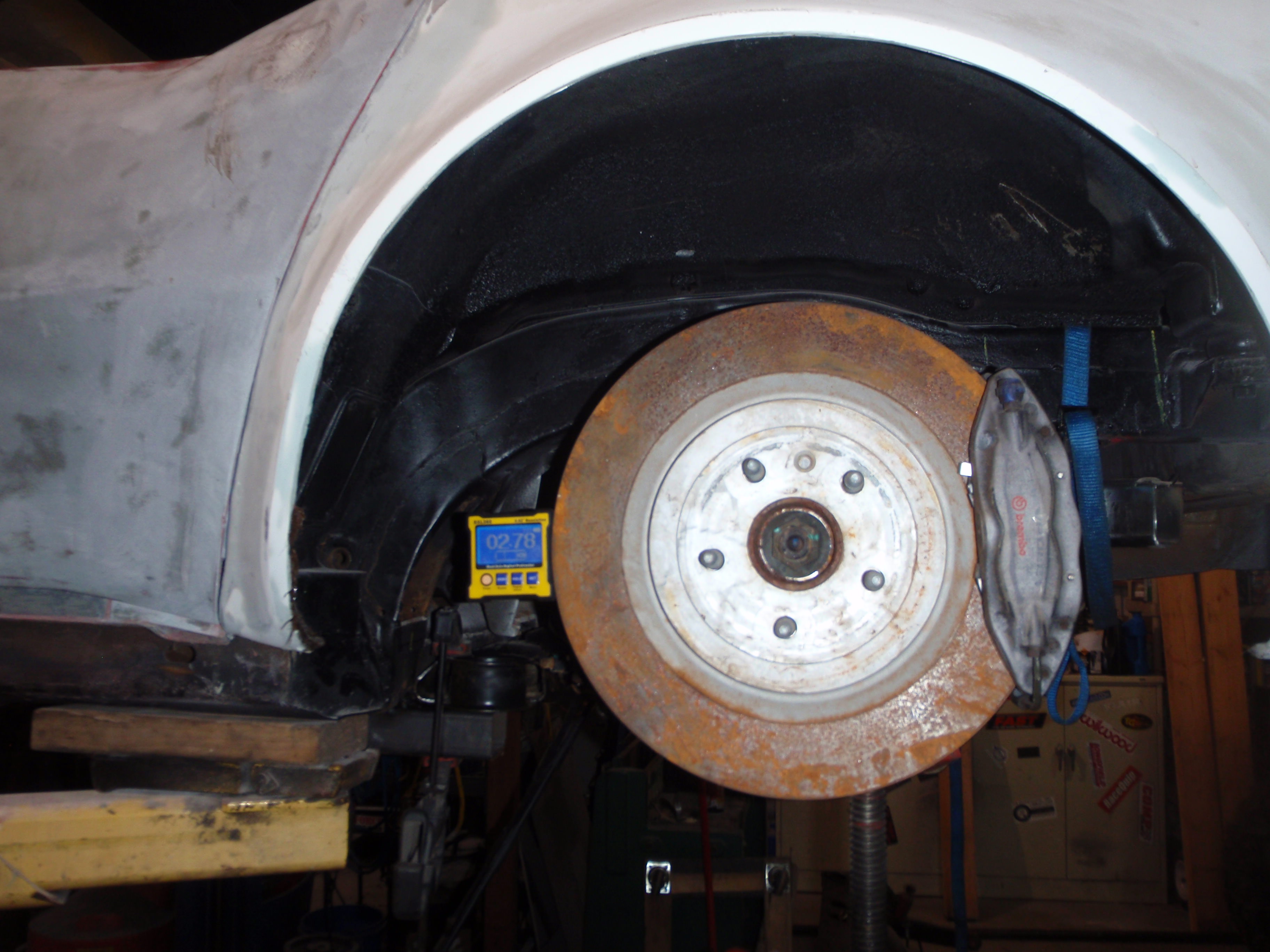
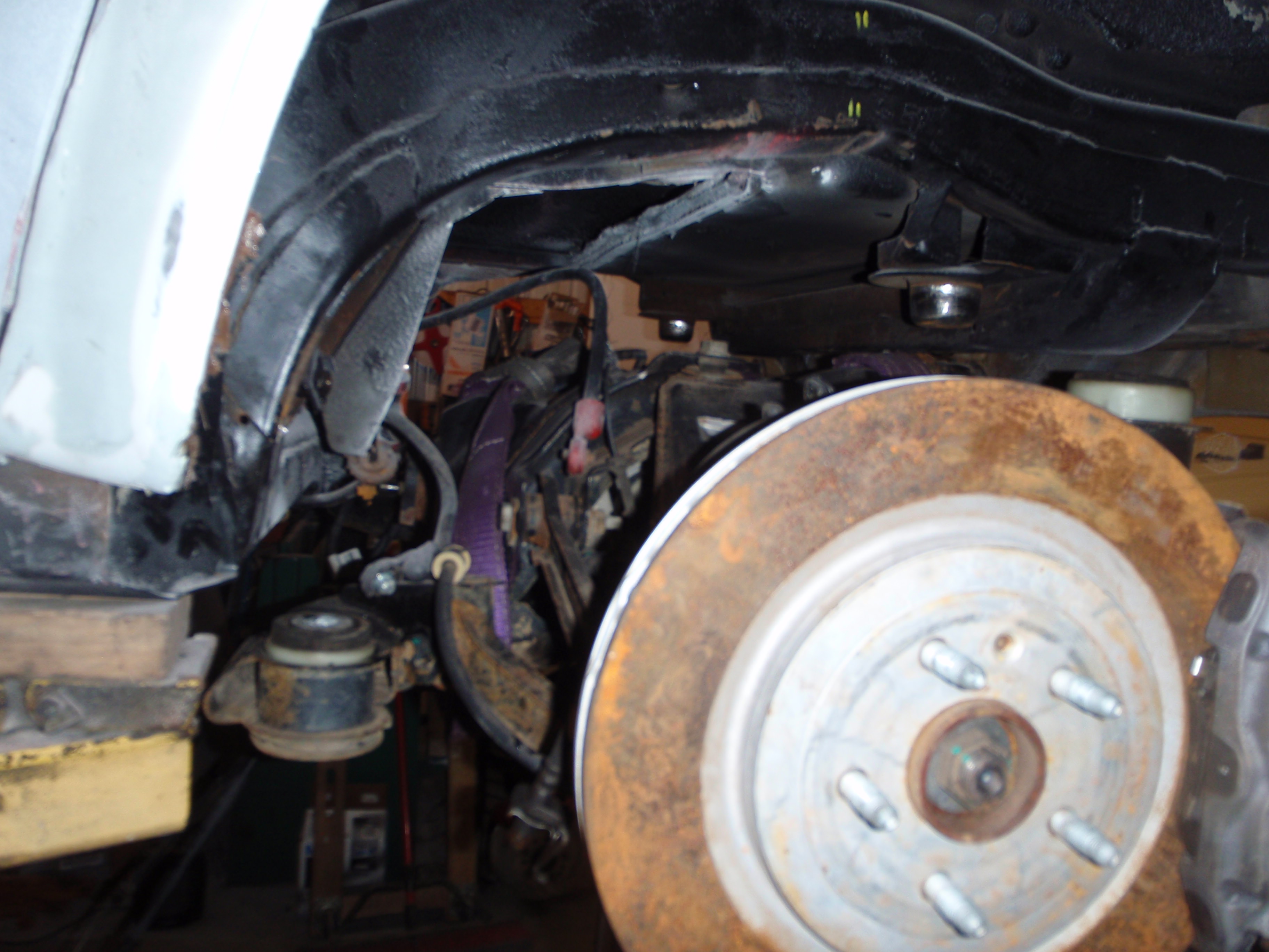
3 degrees at full compression (which is about 2" into the tire so not going that far)
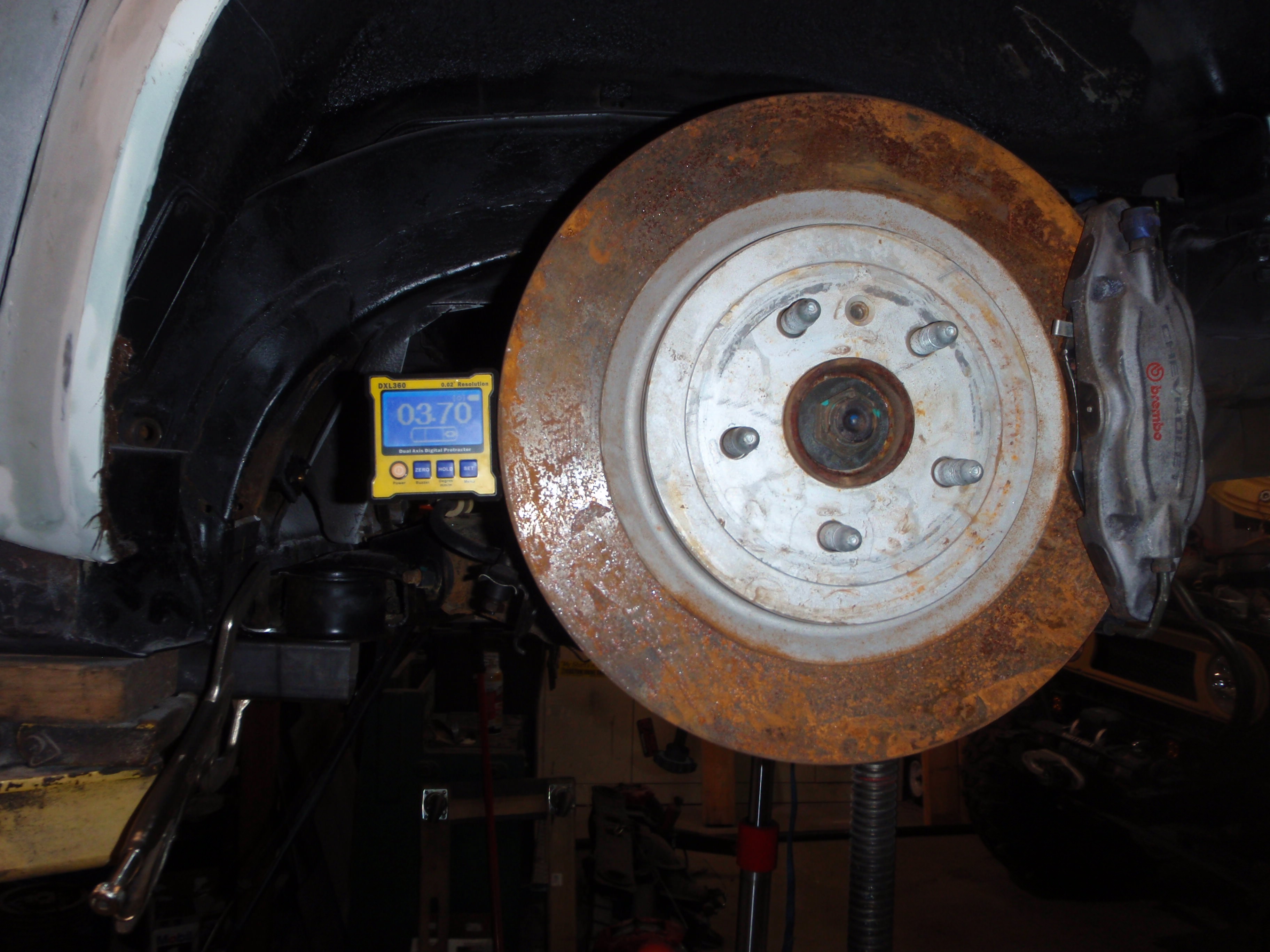
I know it seems like 4 but it was zeroed and moved before this picture....
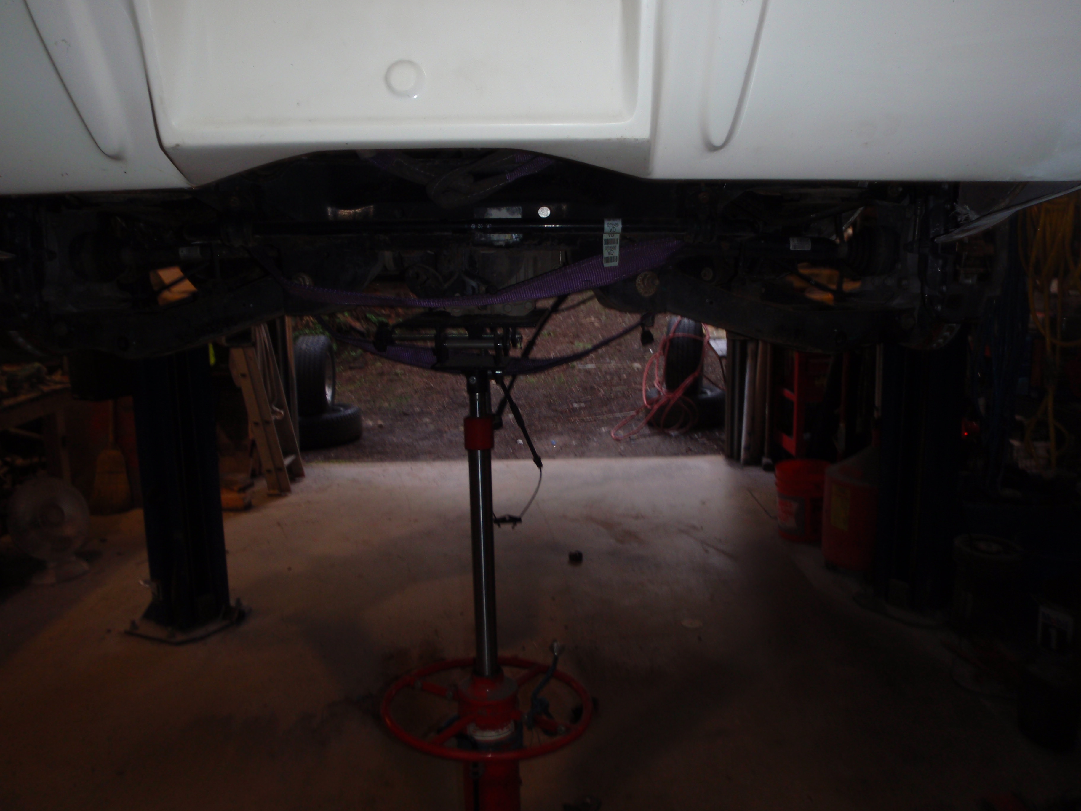
that's about middle of the travel (it has roughly 6 inches maybe a touch more if pushed - which is kind of amazing itself since that's about 1 inch more then my H3 Hummer had on the front)
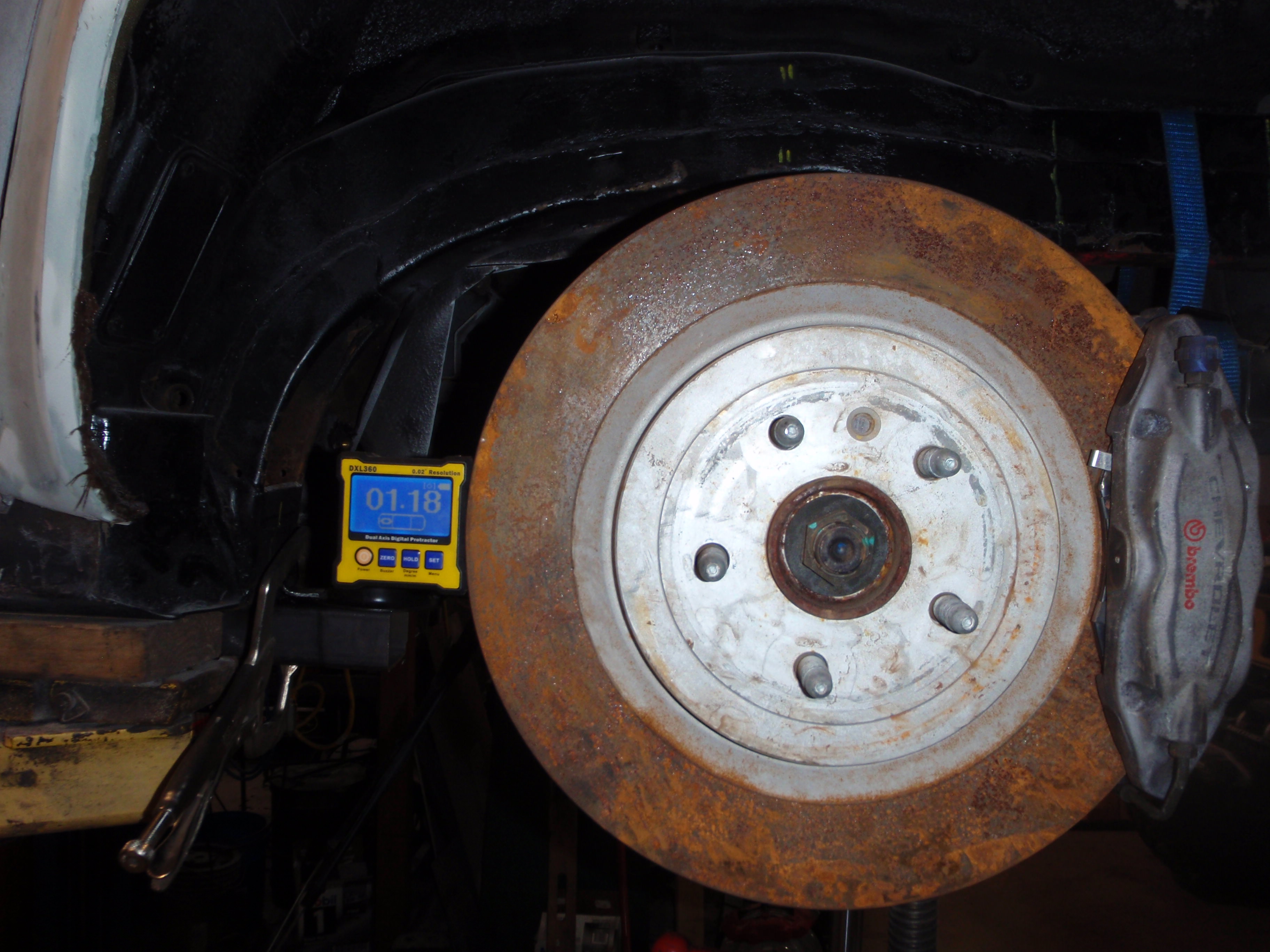
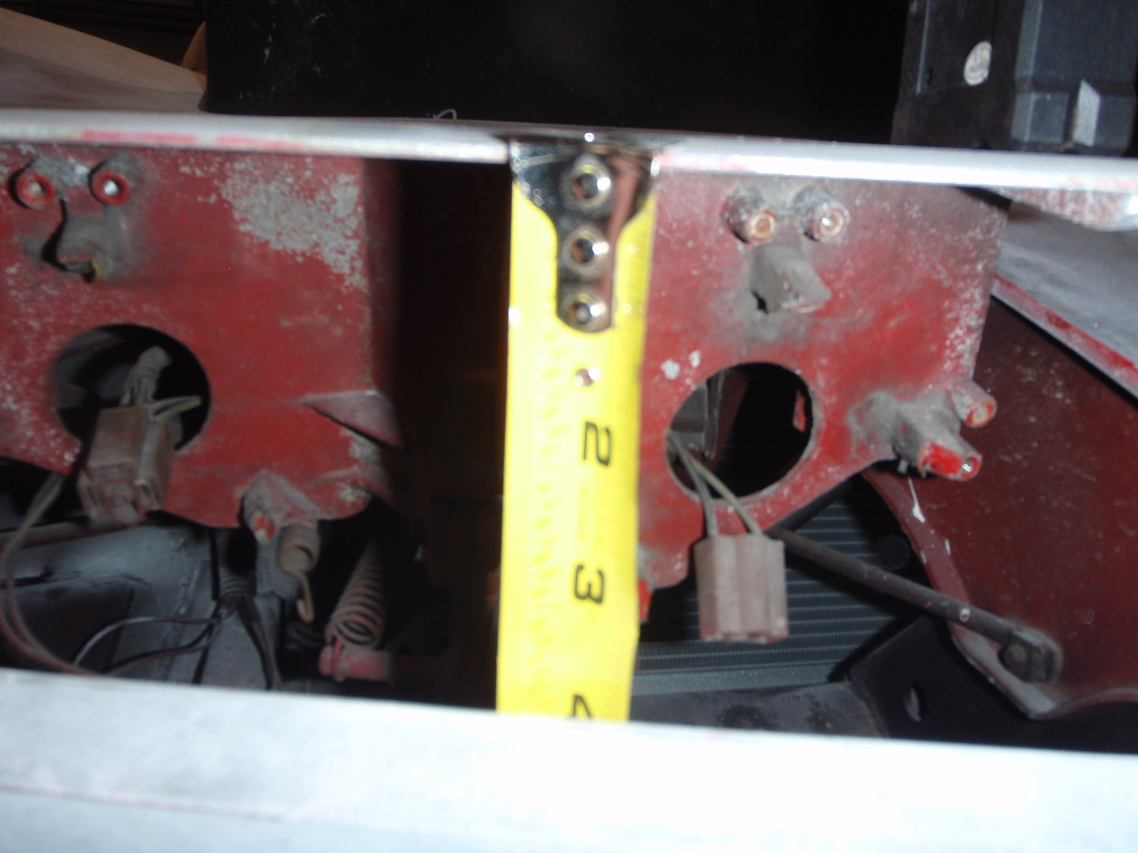
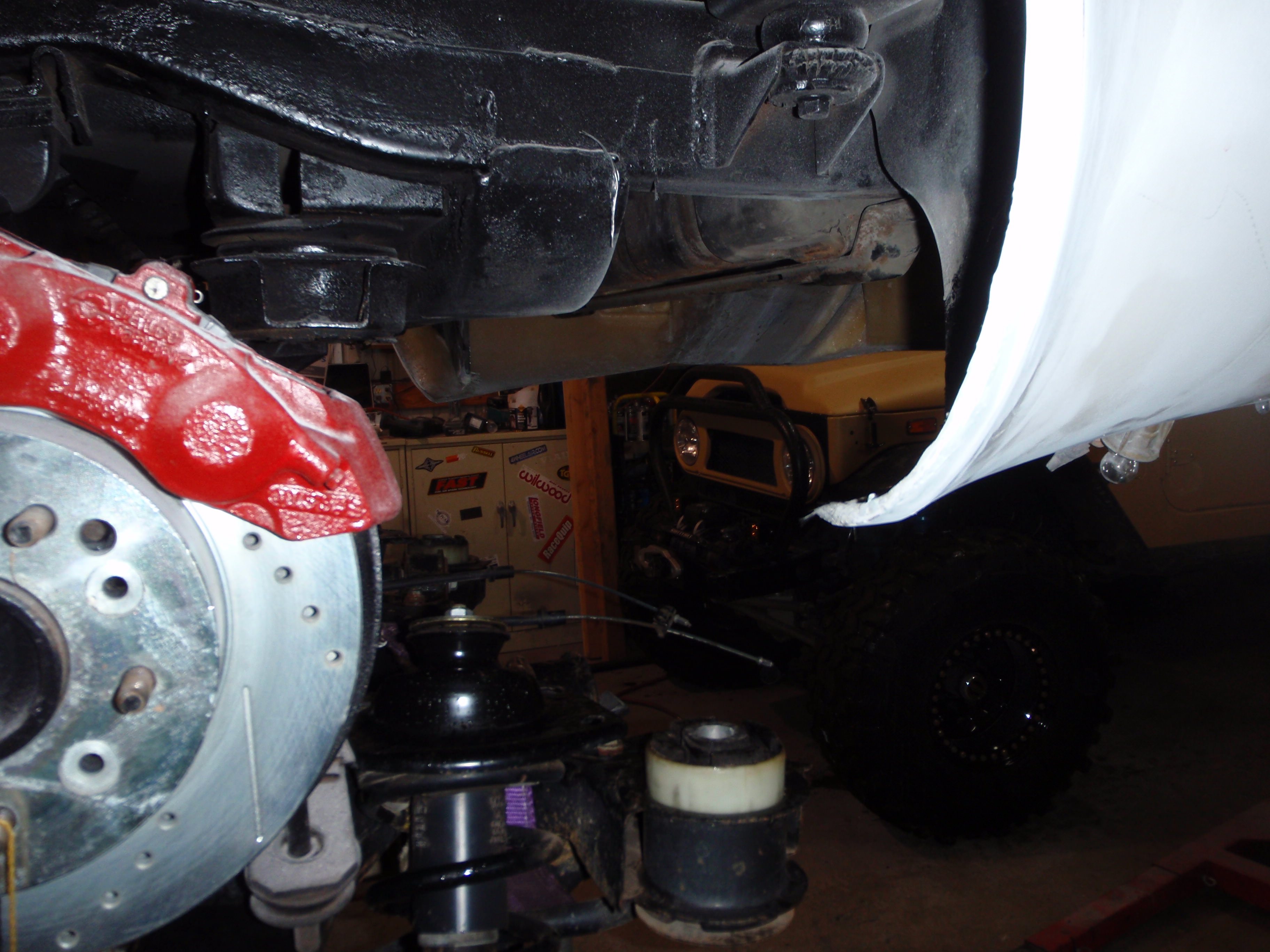
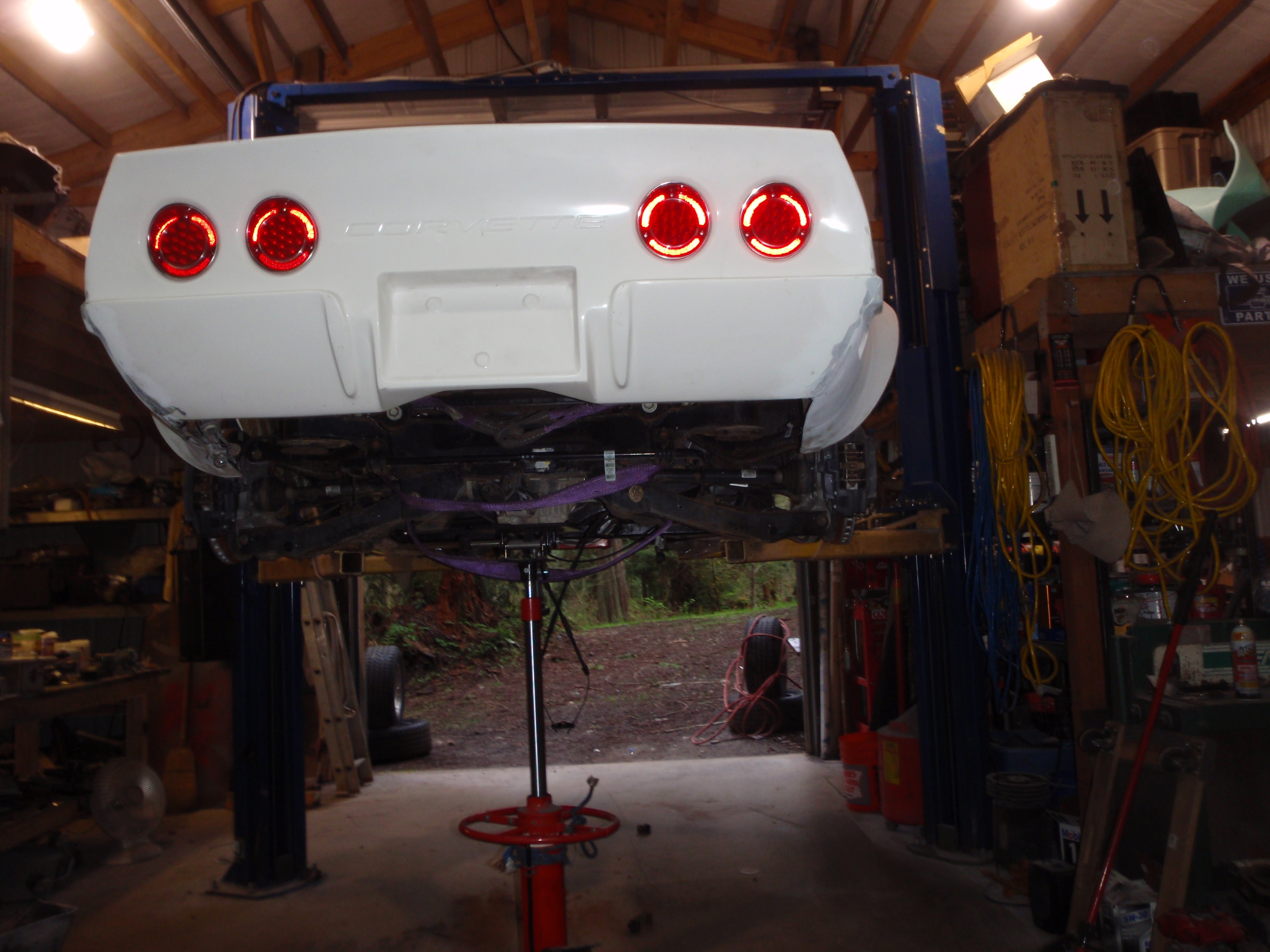
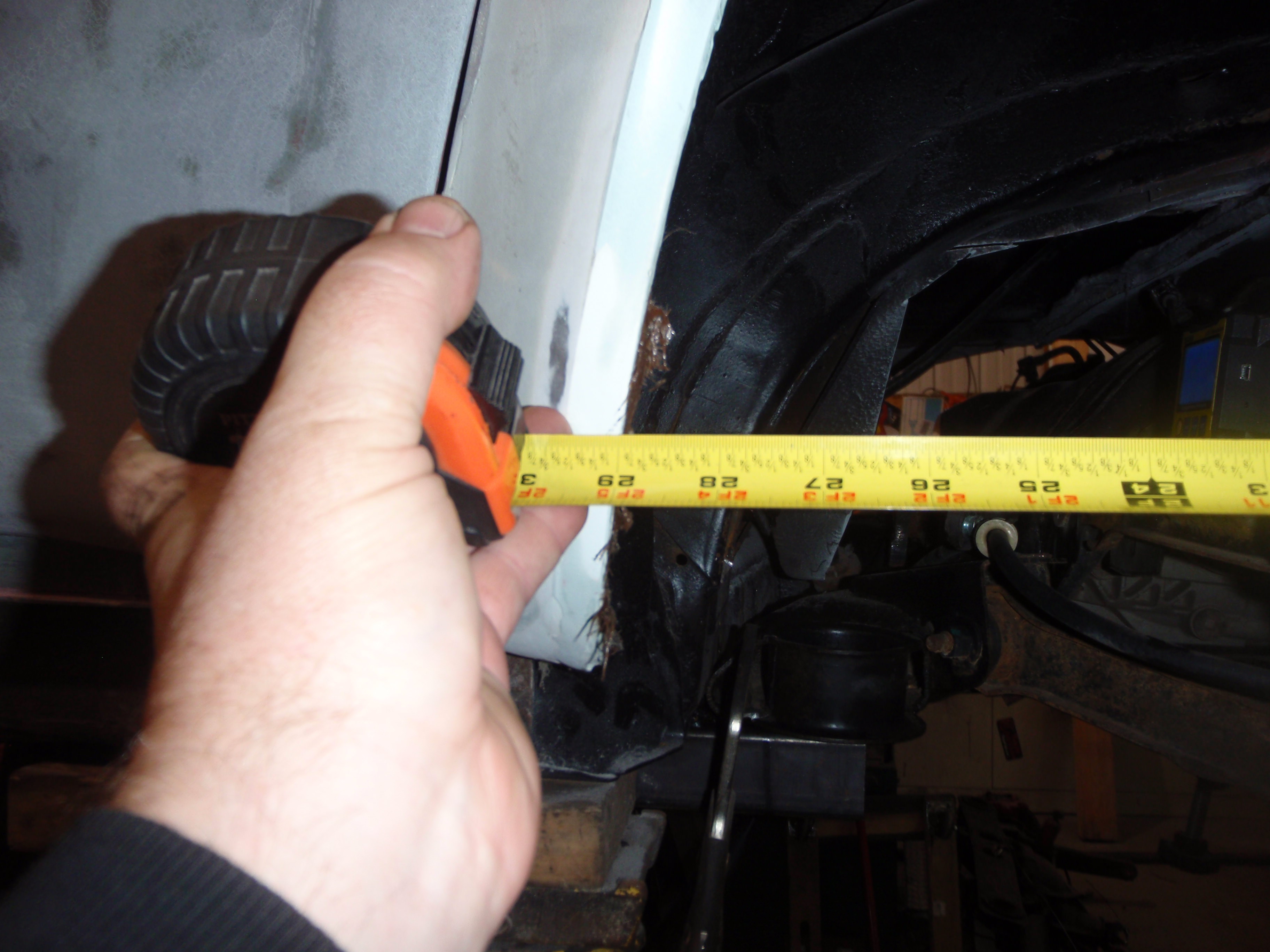
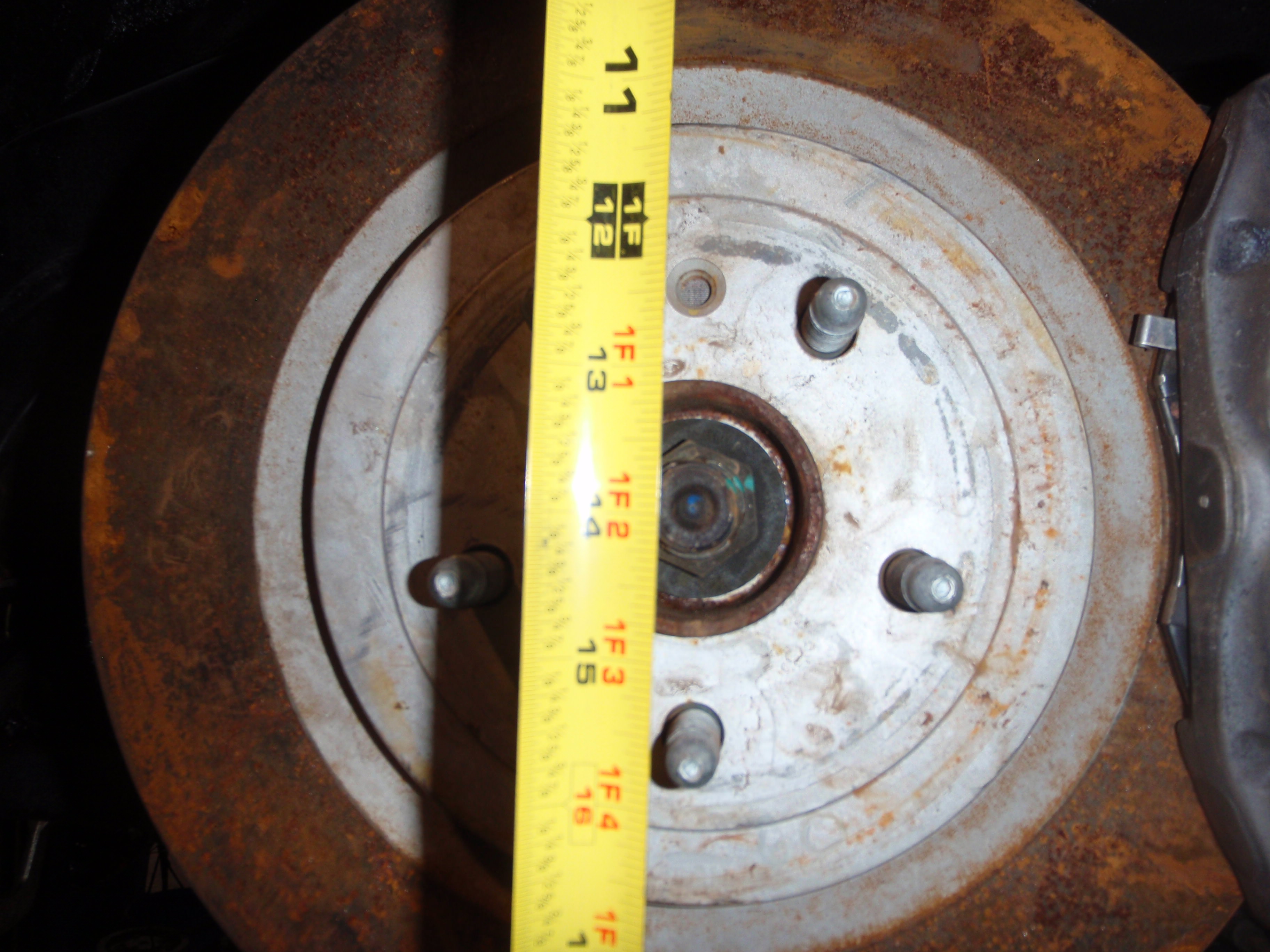
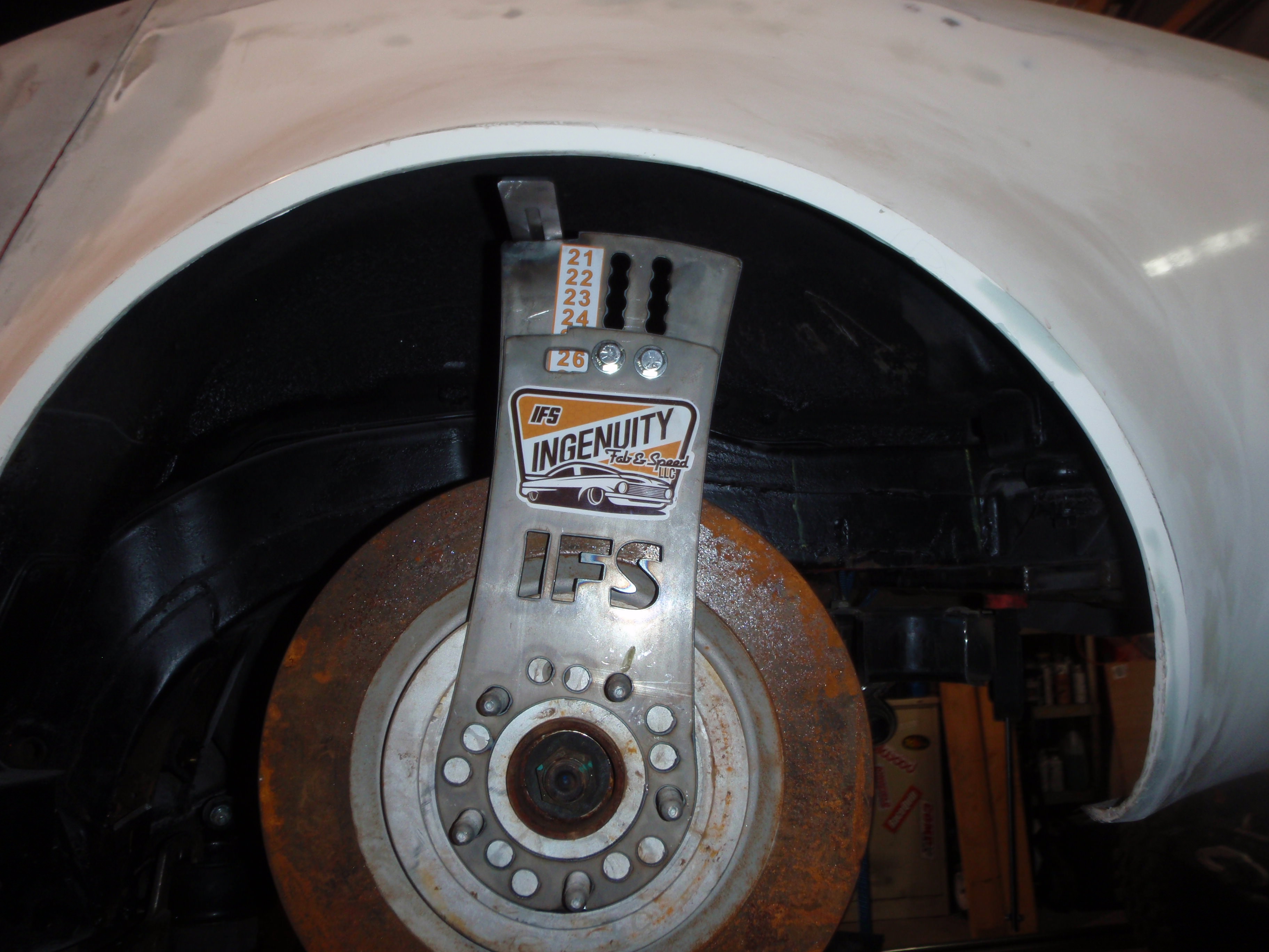
29" opening at full drop
If I was a snot, I'd not tell you that it's really easy to get the suspension where it needs to be....
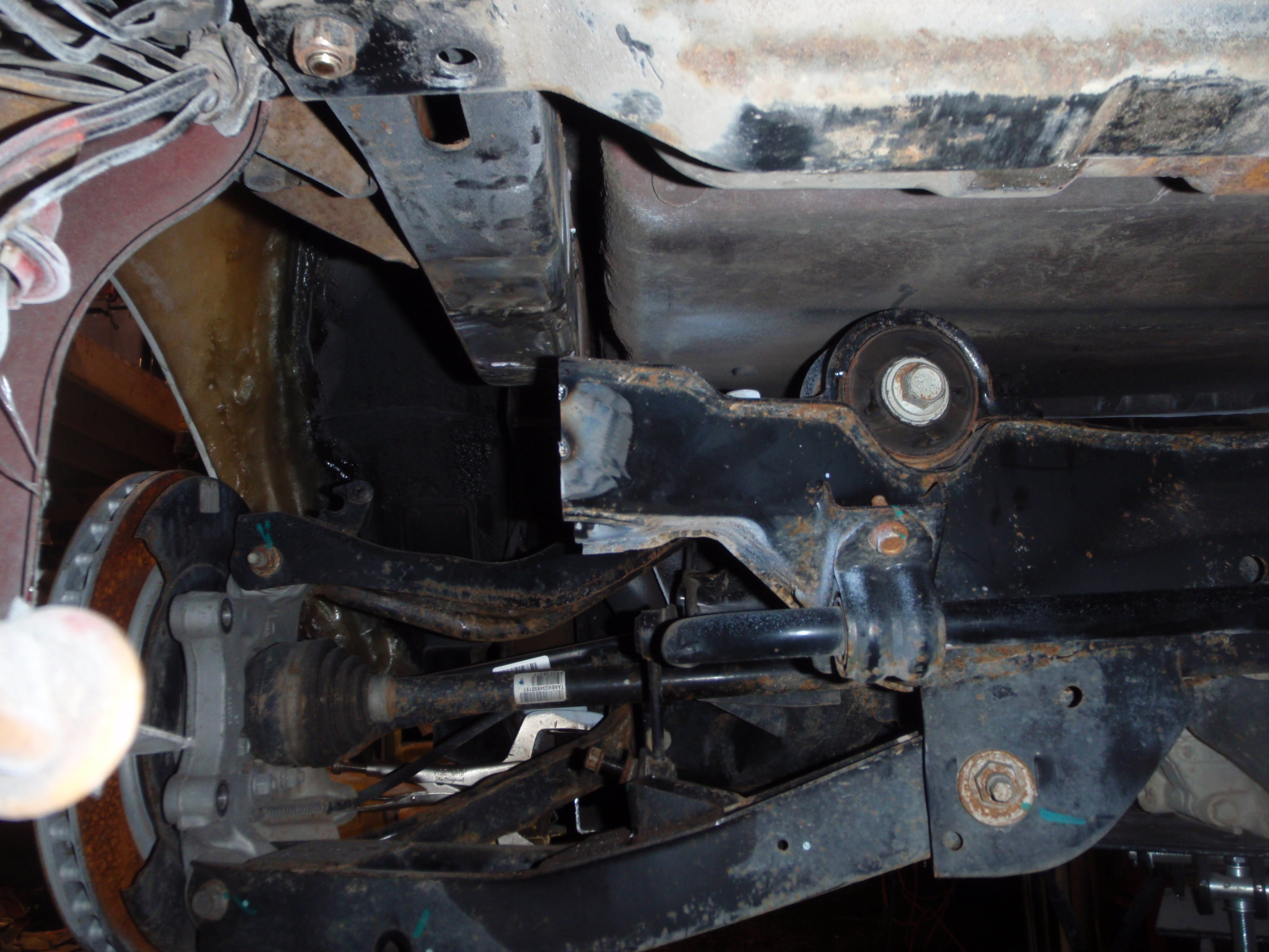
level this bar - at ride height this bar must ABSOLUTELY be level.... the suspension is designed to toe in/toe out during travel - and it actually helps it turn, but it must be level otherwise steering inputs won't be predictable.
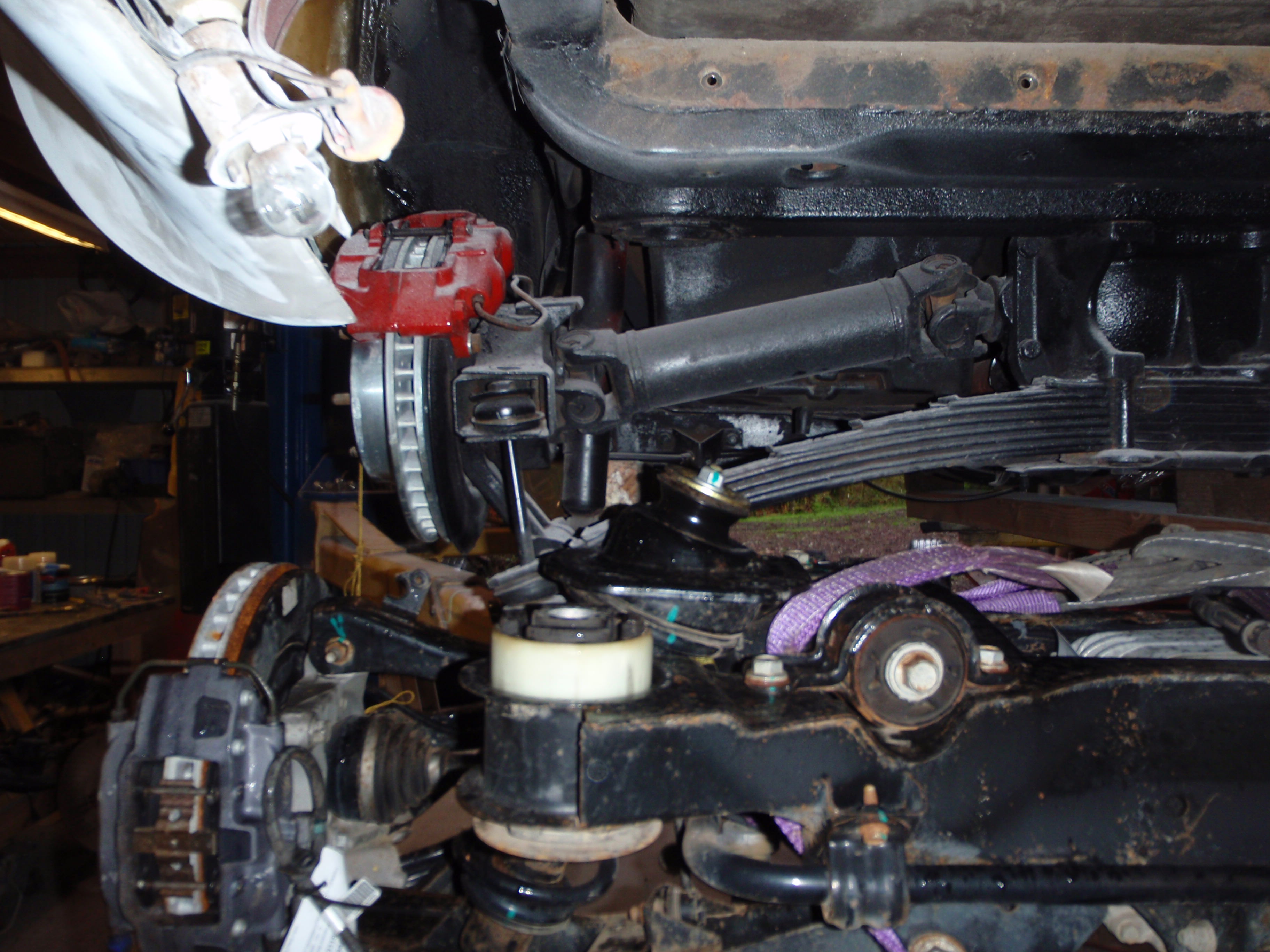
all that's left is rotating the axle so the tire goes (close to) straight up and down in the wheel opening. With that said, advanced suspension says you want the wheels to get closer together on the inside of the turn and wider on the outside.... HOWEVER, not too much otherwise you'll have to steer after every large bump... in this case, 1* is enough (which is back to my prediction as to the orientation of the axle as view from the side... tl;dr - front needs to go down about 1 1/2 inches, I think)
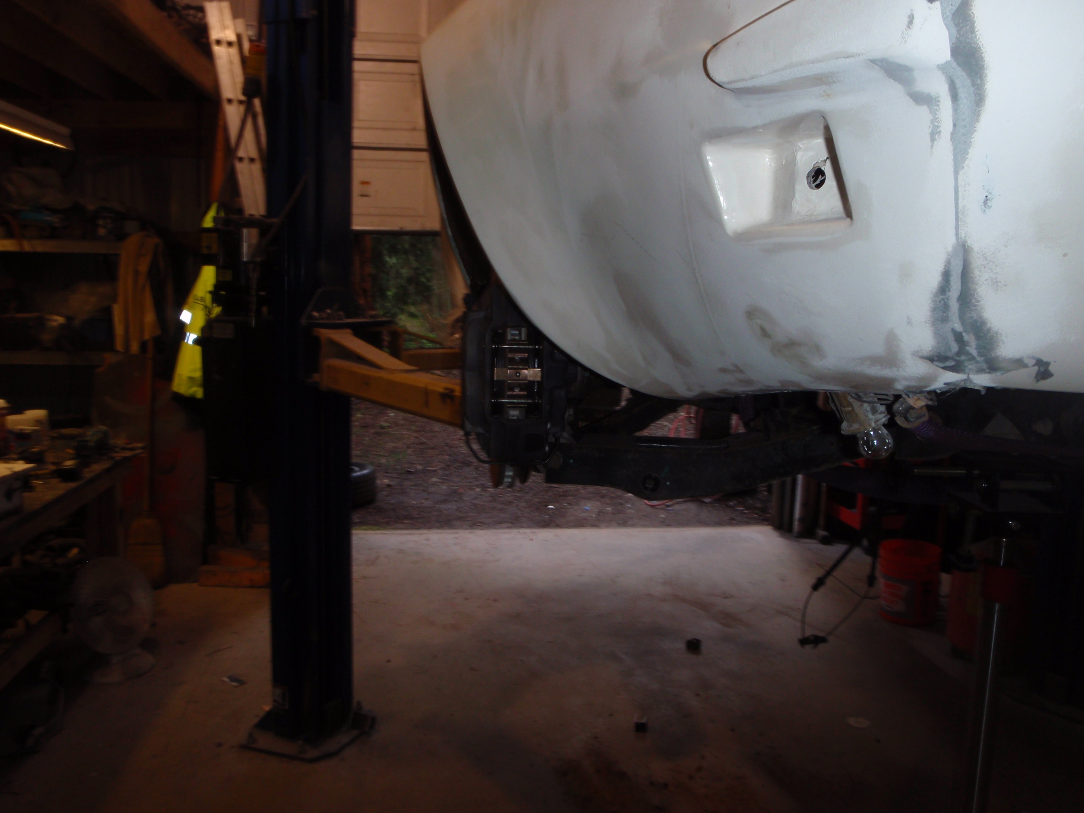
the tire size Custom Image Corvette designed the flares for is 28".... that means this is basically the most downward travel
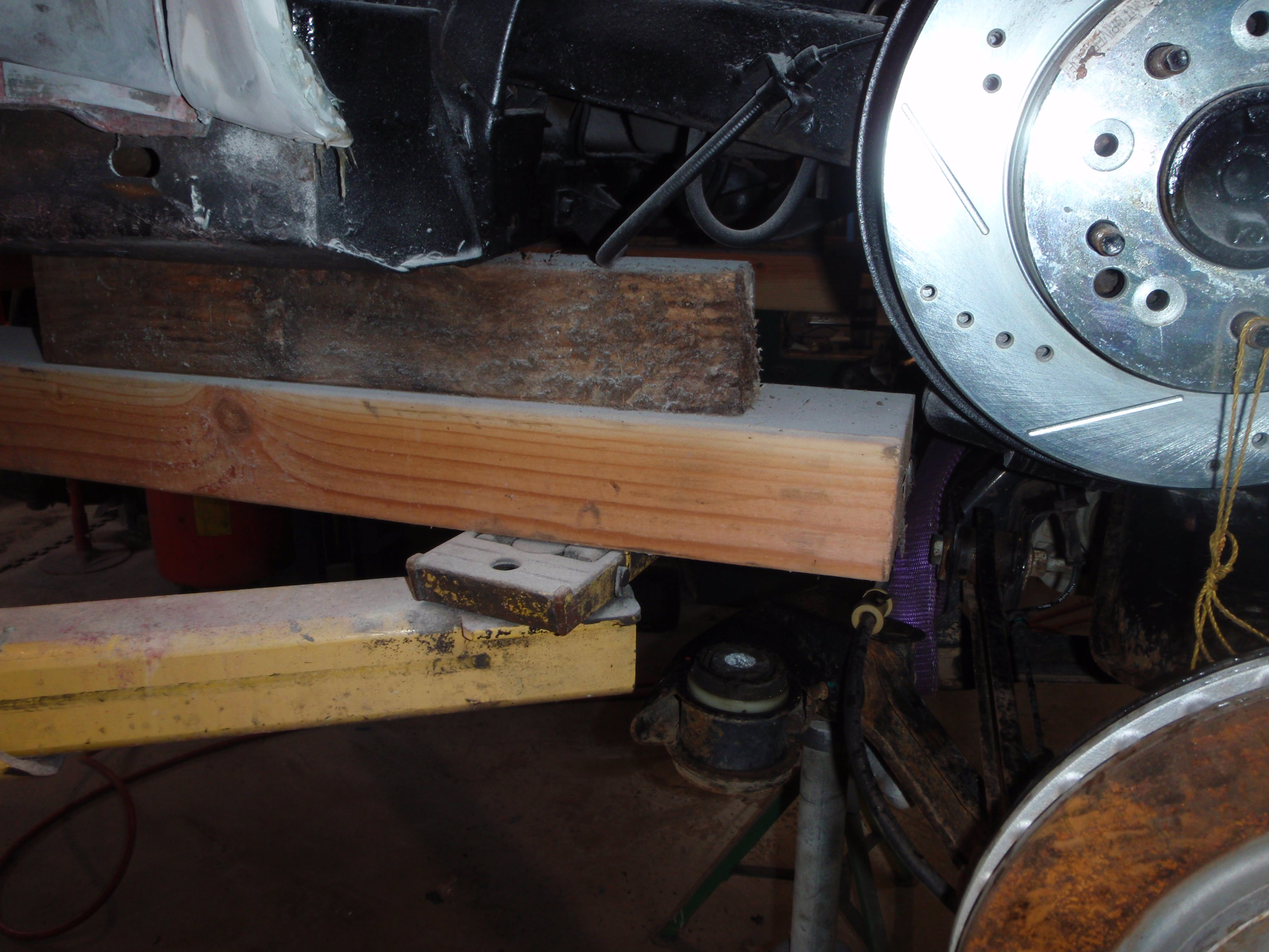
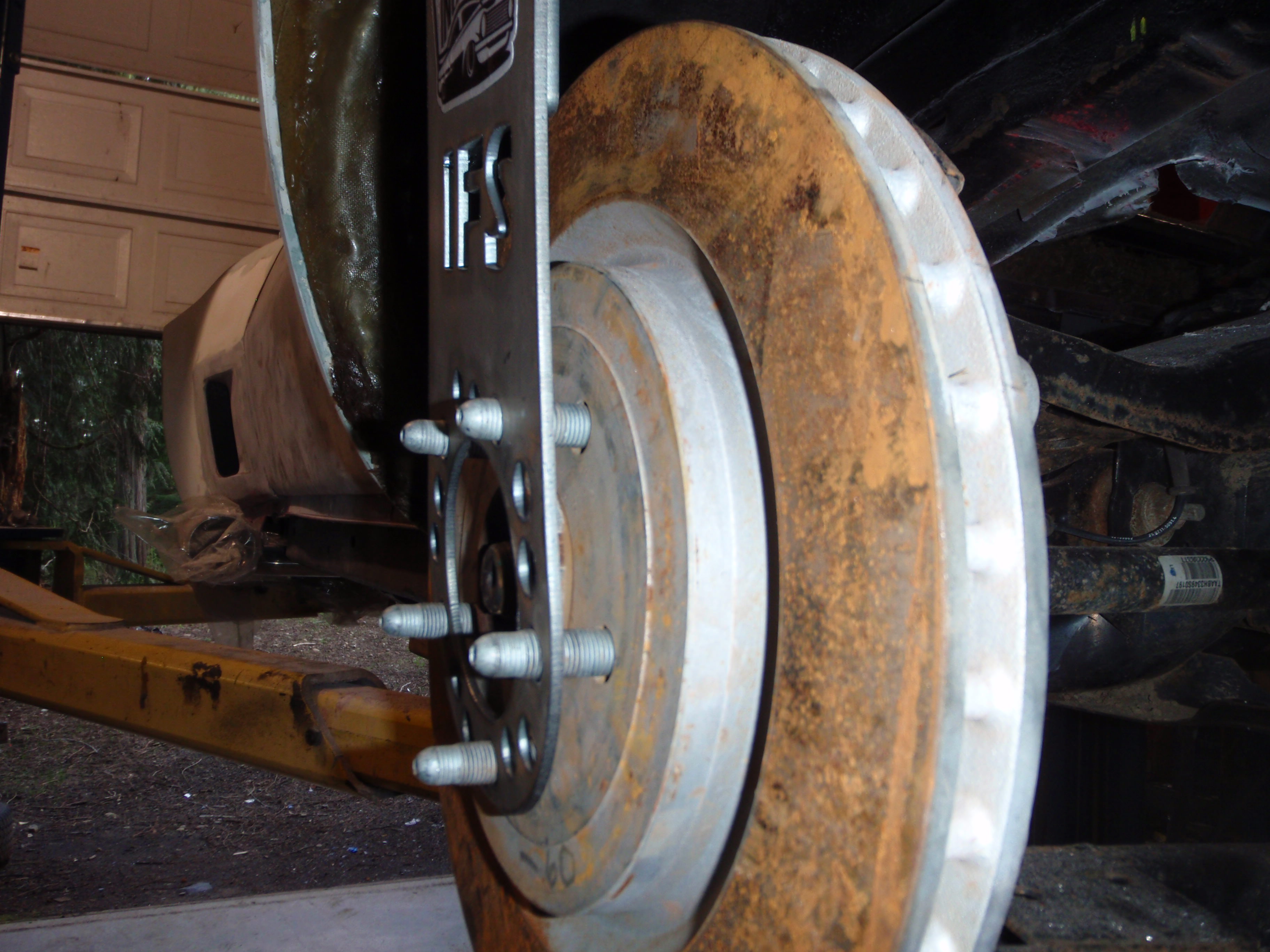
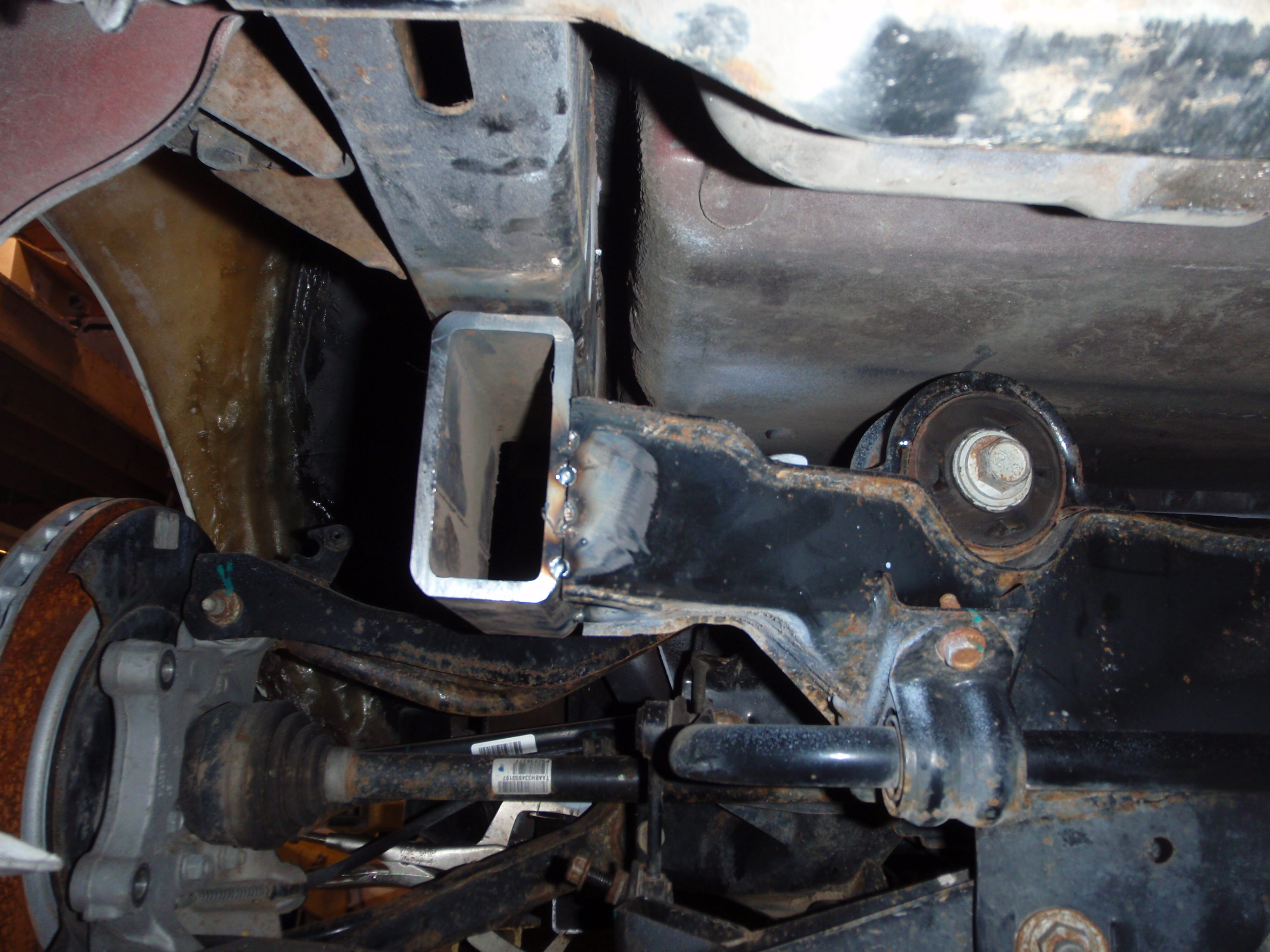
Sunday I said I needed to take 1/4 inch off... no, it needs 1/2 inch
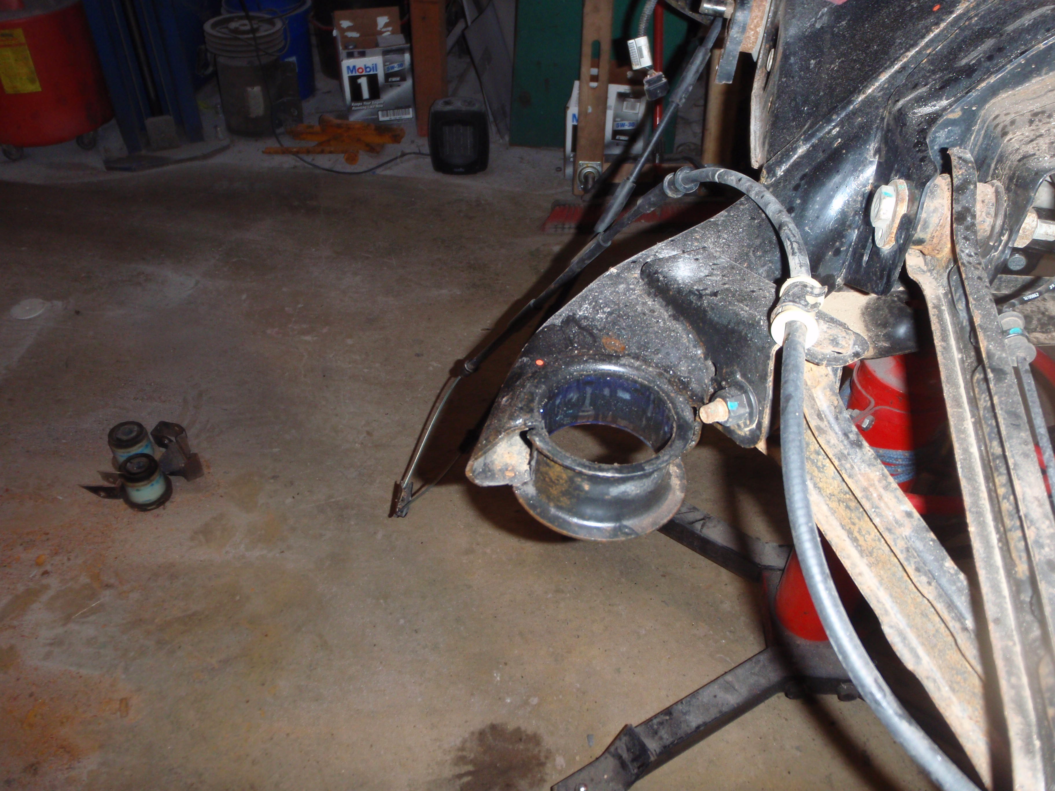
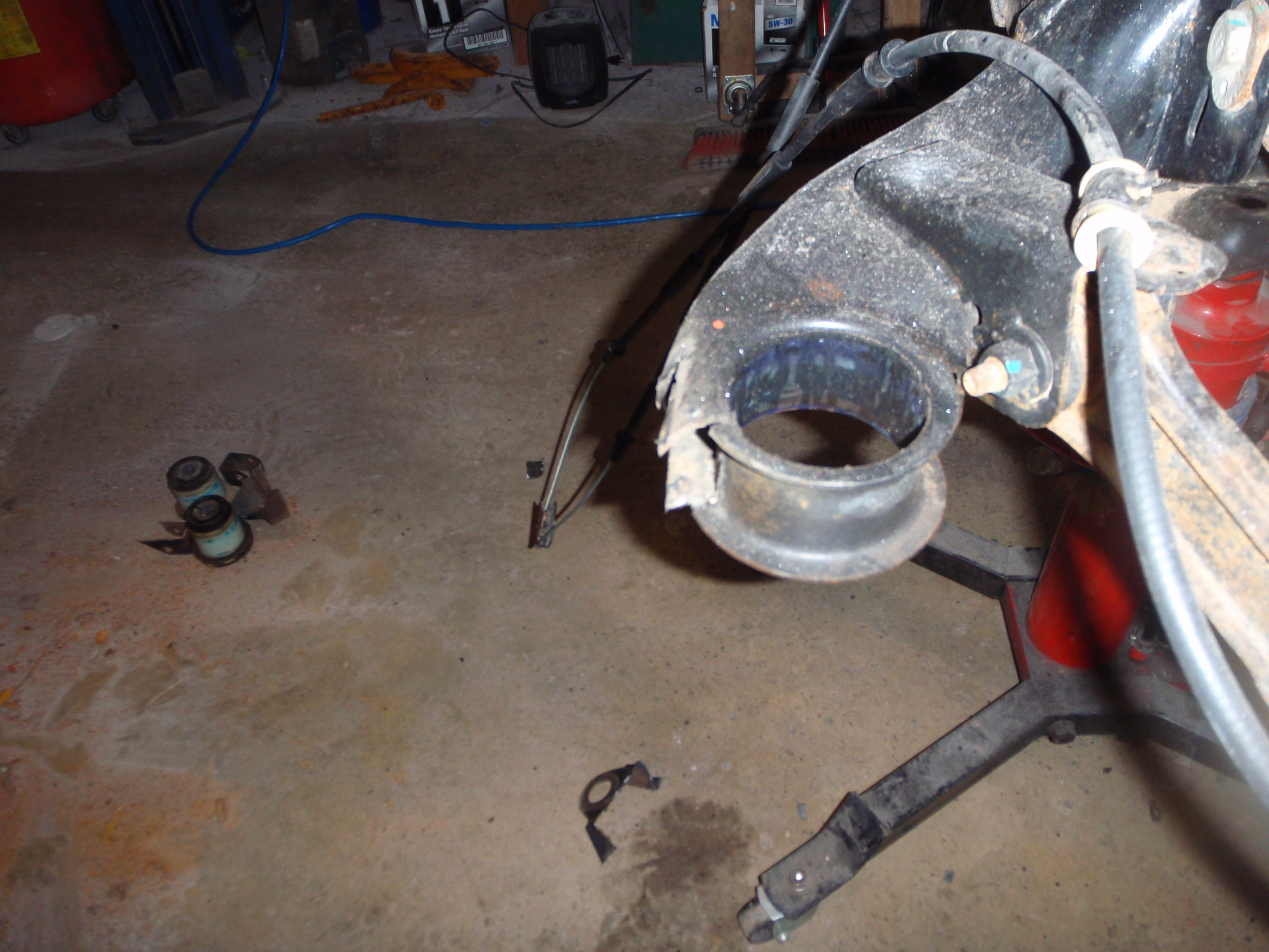
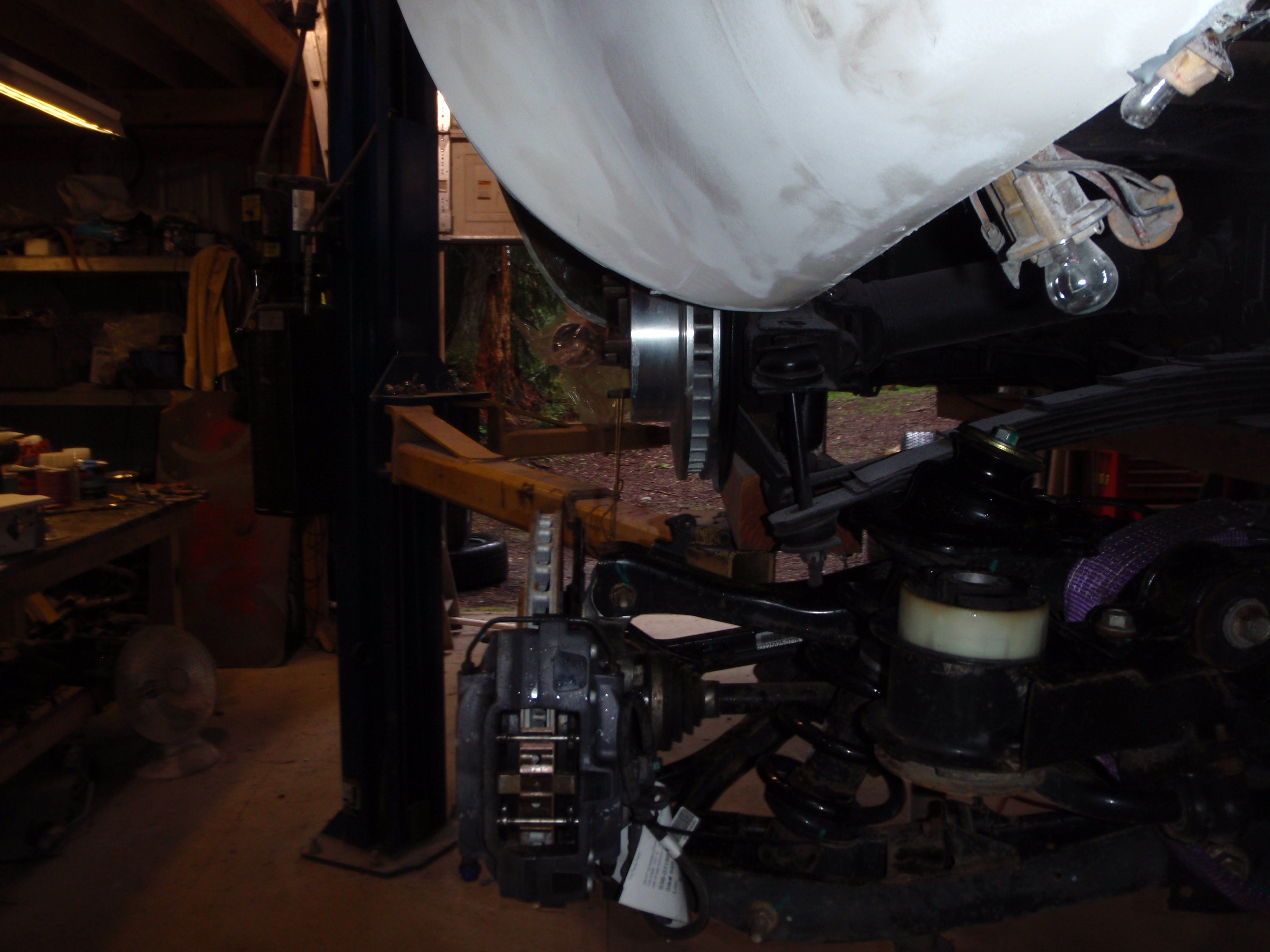
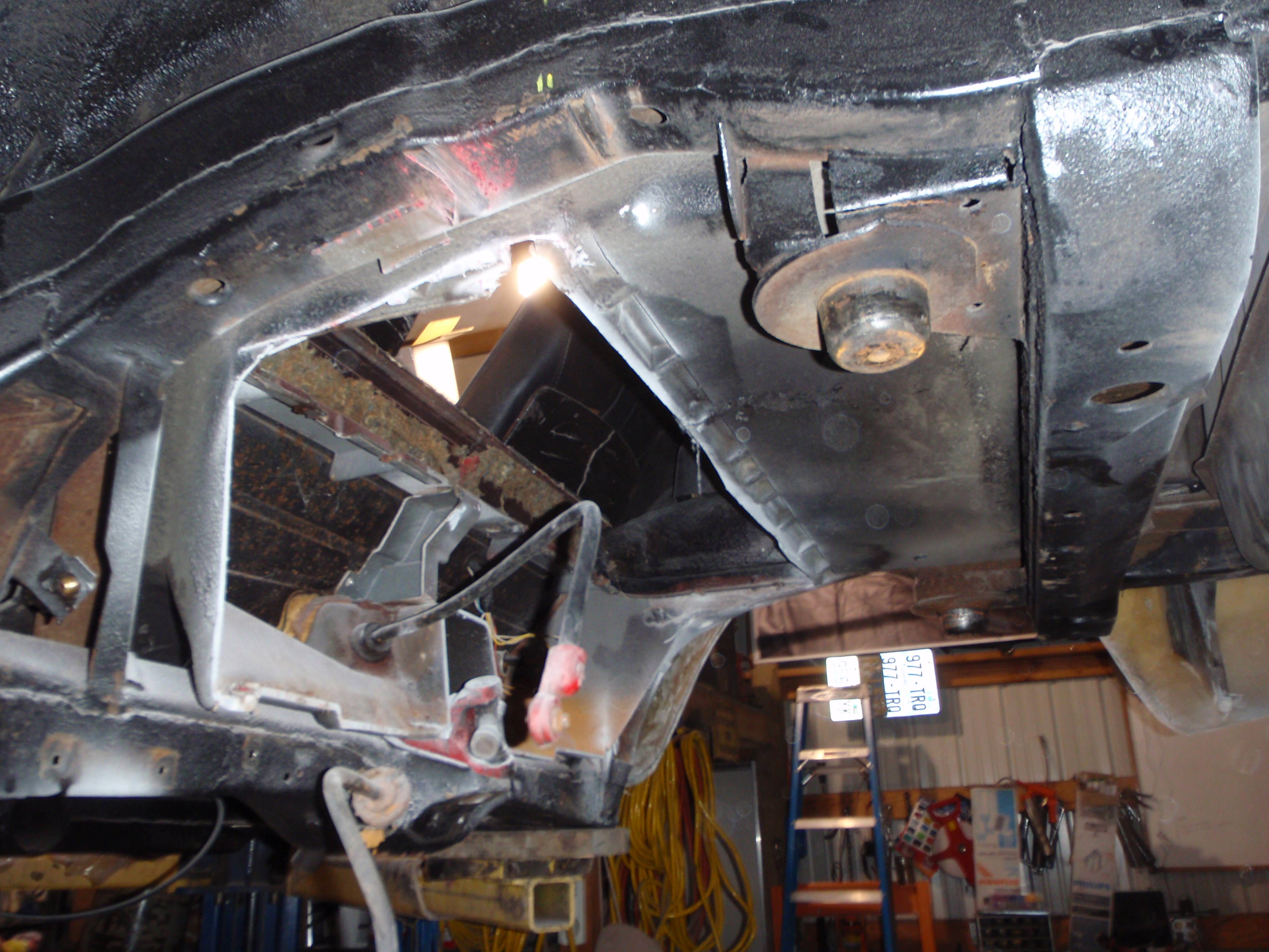
and knock that cussable front support off
done
and if you look really closely, you'll see the wheel is more centered
Thursday I'm going to start making front brackets then start pondering what the rear is going to look like. the last fun bit will be figuring out the coil over mount... there is an elegant solution for the driveshaft... but that you'll just have to wait to see
So this set of pictures is after disconnecting the sway bar and seeing how close to perpendicular the axle is moving. I think, this is just a guess, but I think the mounts would be about 1 1/2 below the cross bar on the C3... no big deal to cut and re-shape, but that's my eduguess as to where this is going to end up
pictures
zero(ish) at full drop
3 degrees at full compression (which is about 2" into the tire so not going that far)
I know it seems like 4 but it was zeroed and moved before this picture....
that's about middle of the travel (it has roughly 6 inches maybe a touch more if pushed - which is kind of amazing itself since that's about 1 inch more then my H3 Hummer had on the front)
29" opening at full drop
If I was a snot, I'd not tell you that it's really easy to get the suspension where it needs to be....
level this bar - at ride height this bar must ABSOLUTELY be level.... the suspension is designed to toe in/toe out during travel - and it actually helps it turn, but it must be level otherwise steering inputs won't be predictable.
all that's left is rotating the axle so the tire goes (close to) straight up and down in the wheel opening. With that said, advanced suspension says you want the wheels to get closer together on the inside of the turn and wider on the outside.... HOWEVER, not too much otherwise you'll have to steer after every large bump... in this case, 1* is enough (which is back to my prediction as to the orientation of the axle as view from the side... tl;dr - front needs to go down about 1 1/2 inches, I think)
the tire size Custom Image Corvette designed the flares for is 28".... that means this is basically the most downward travel
Sunday I said I needed to take 1/4 inch off... no, it needs 1/2 inch
and knock that cussable front support off
done
and if you look really closely, you'll see the wheel is more centered
Thursday I'm going to start making front brackets then start pondering what the rear is going to look like. the last fun bit will be figuring out the coil over mount... there is an elegant solution for the driveshaft... but that you'll just have to wait to see
The following users liked this post:
Metalhead140 (04-18-2018)
04-20-2018, 12:37 AM
#159
Melting Slicks
so I measured. 26x12.3 .... you'll see how I verified this at the end
oh an 9" backspace ... means I can use Z06 wheels
of course all things do not work perfectly the first time.... one hole was just a tad undersized.. easy fix on the drill press
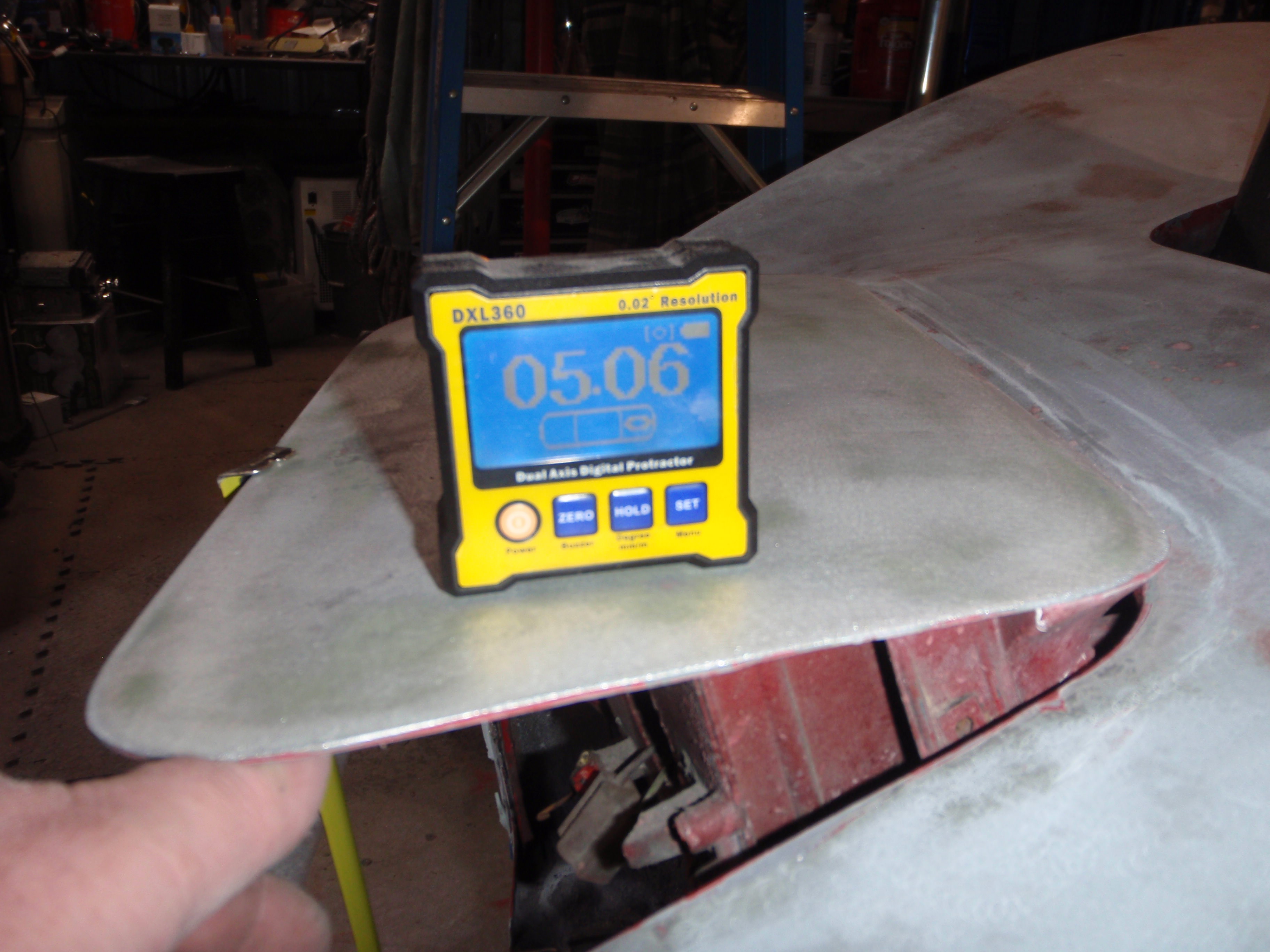
1 degree difference - the transmission is 2.85 degrees
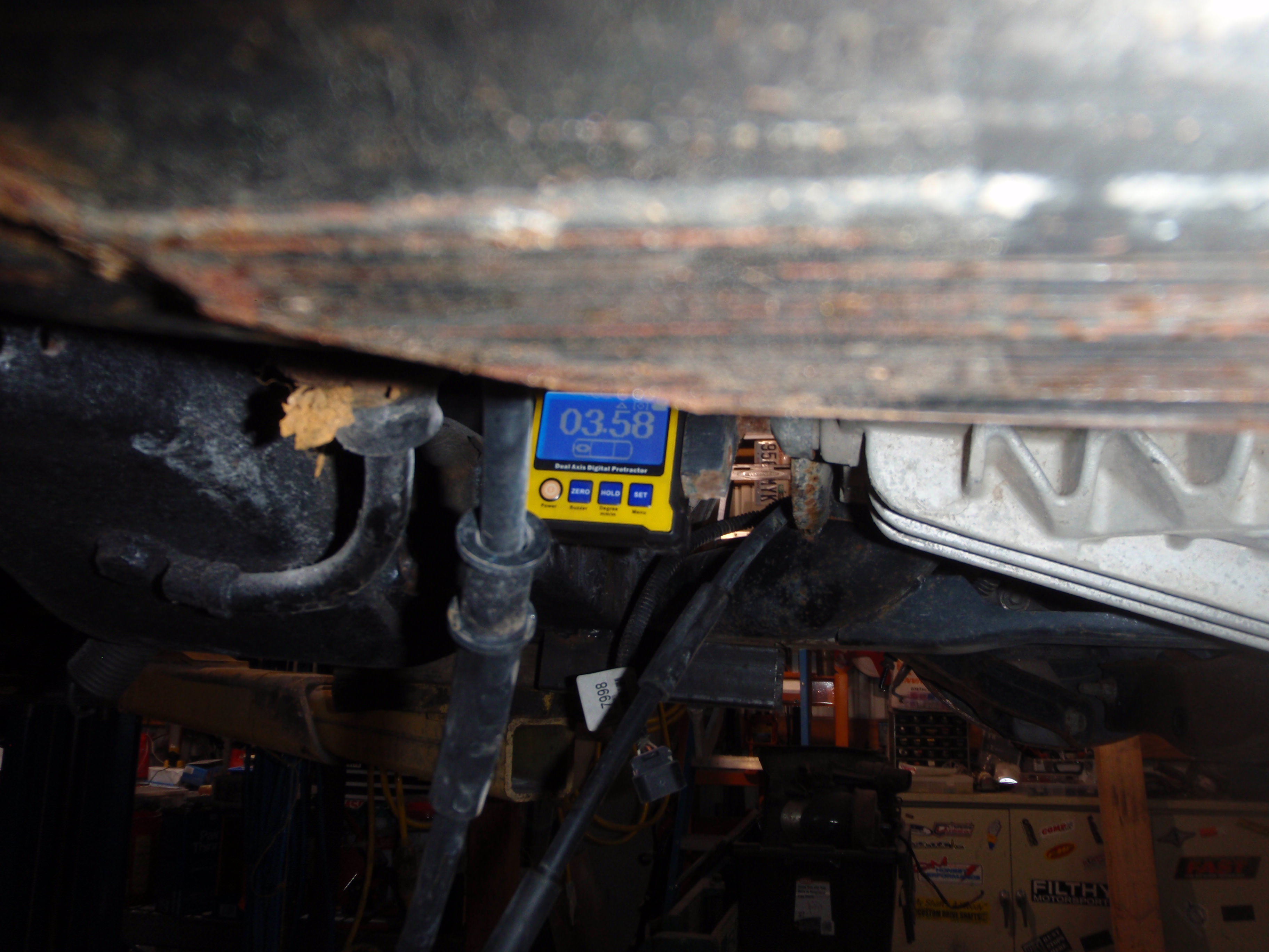
now to put it in place for permanence
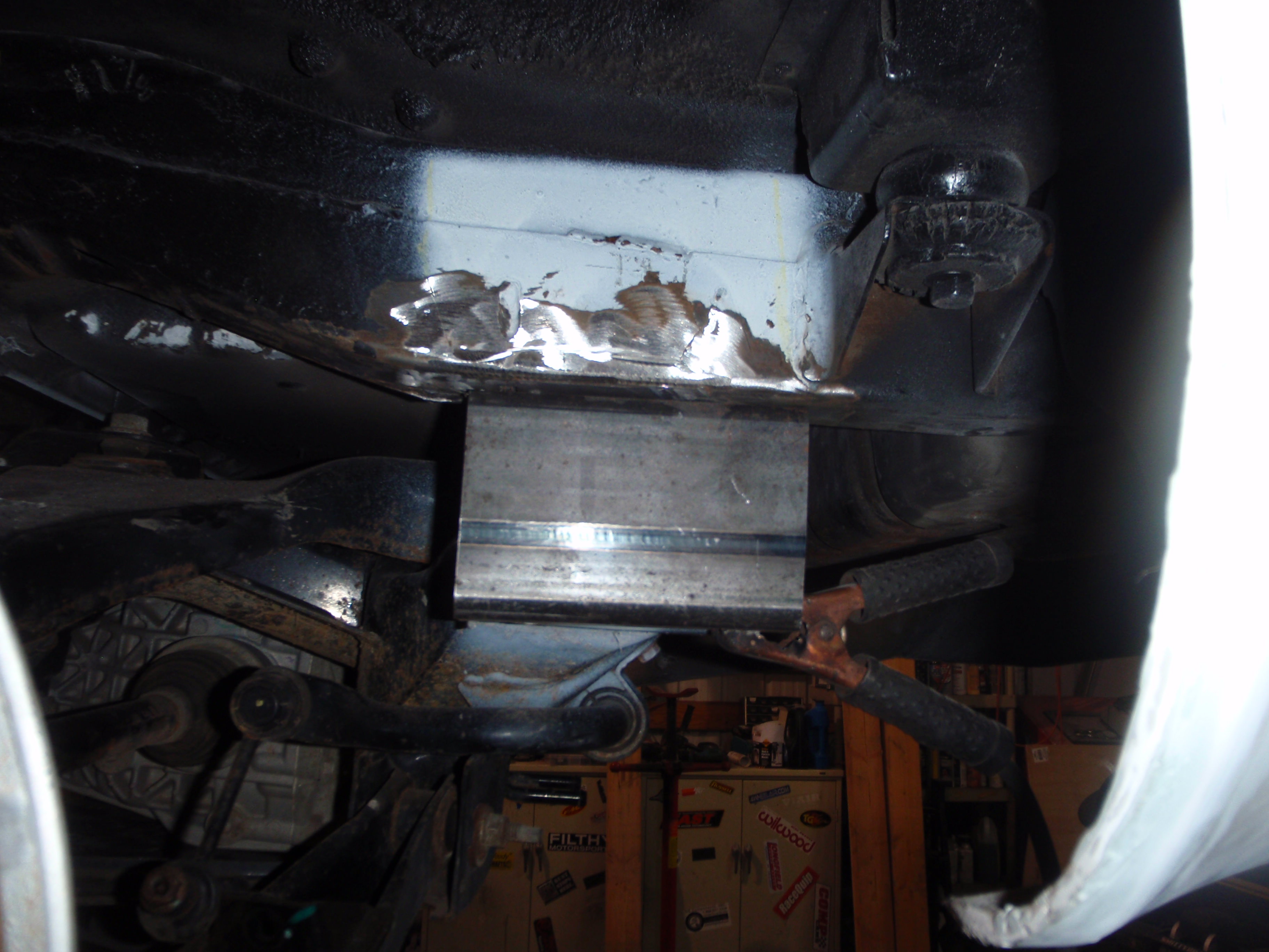
trim, tack
knock apart,
tack again in the right spot
get the welds I can't reach from the bottom
and there it is... front is still on temp stands, but it should all be in place Sunday
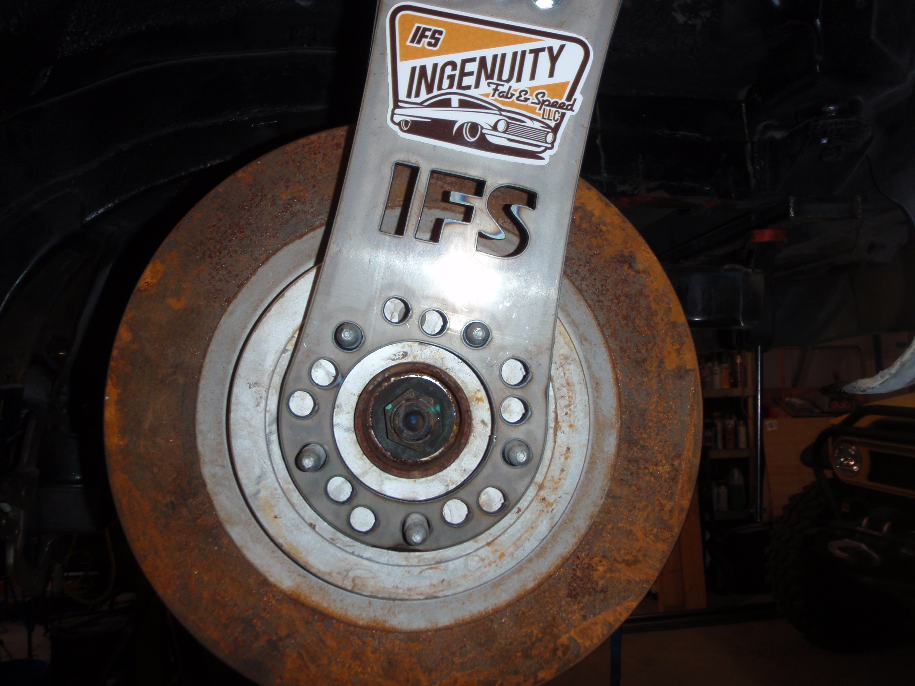
hmmm,, I think these brakes are bigger then stock
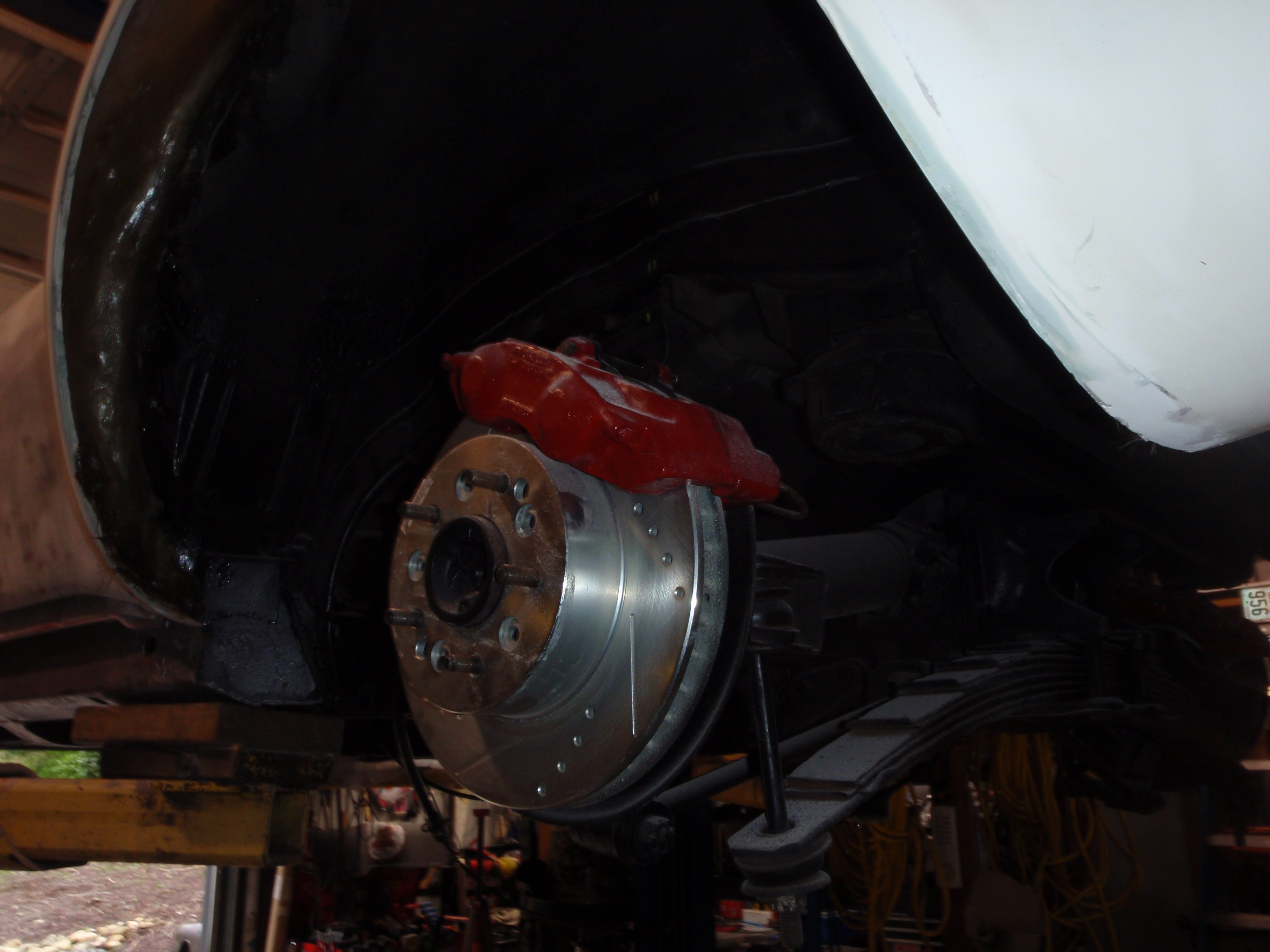
verification.... fits
and yes, centered even
oh an 9" backspace ... means I can use Z06 wheels
of course all things do not work perfectly the first time.... one hole was just a tad undersized.. easy fix on the drill press
1 degree difference - the transmission is 2.85 degrees
now to put it in place for permanence
trim, tack
knock apart,
tack again in the right spot
get the welds I can't reach from the bottom
and there it is... front is still on temp stands, but it should all be in place Sunday
hmmm,, I think these brakes are bigger then stock
verification.... fits
and yes, centered even
The following users liked this post:
Metalhead140 (04-21-2018)
04-21-2018, 04:43 PM
#160
Melting Slicks
Parts arrived...
clever solution (probably should have done the other one so I could use a smaller U-joint but this means I need to put enough motor in front of it to warrant the use of the 1350 u-joint... otherwise, I'll be laughed at).
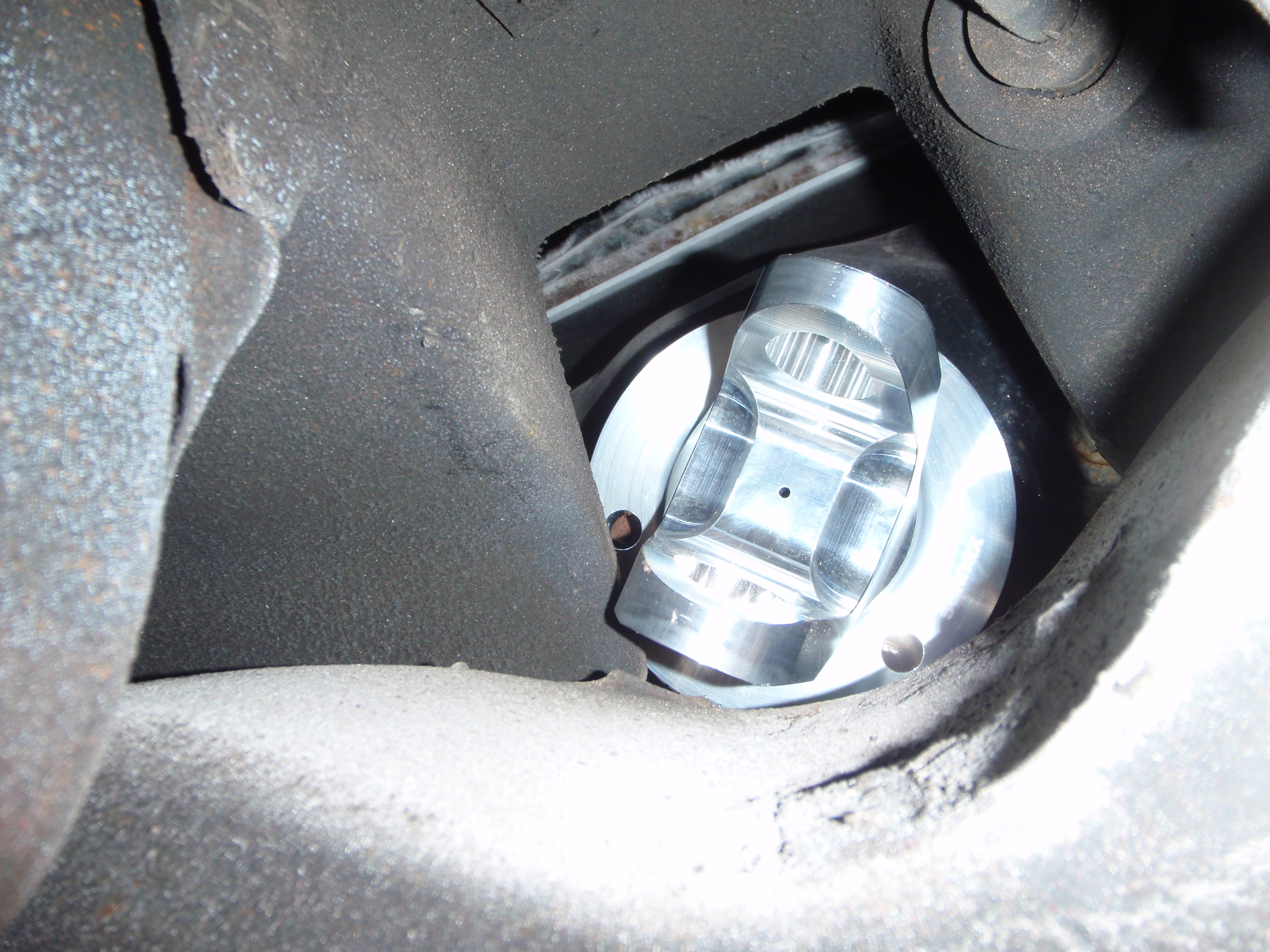
these arrived too.... now all that's left is everything
clever solution (probably should have done the other one so I could use a smaller U-joint but this means I need to put enough motor in front of it to warrant the use of the 1350 u-joint... otherwise, I'll be laughed at).
these arrived too.... now all that's left is everything