
Where does the black ammeter wire connect to?
 02-12-2018, 04:28 PM
#1
Instructor


Thread Starter

Hi,
I replaced my ammeter with a working unit (tested with a 9v battery), but it's not working because I get 12V at the B/W wire, but nothing at the black wire.
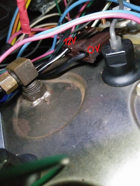
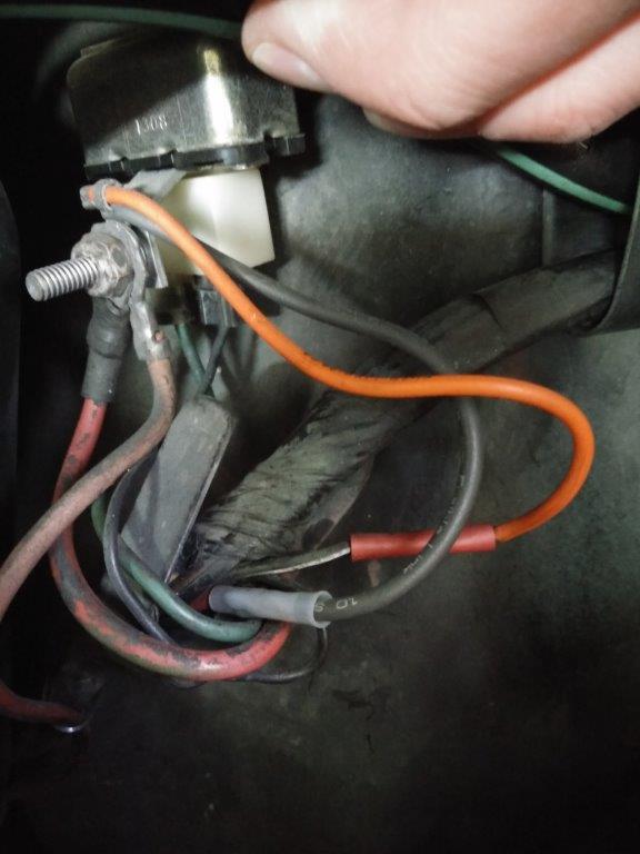
I think the B/W wire connects to the horn relay through the orange fusible link, but I'm not sure where the black wire connects to?
Any thoughts where I should start looking?
Thanks!

I replaced my ammeter with a working unit (tested with a 9v battery), but it's not working because I get 12V at the B/W wire, but nothing at the black wire.
I think the B/W wire connects to the horn relay through the orange fusible link, but I'm not sure where the black wire connects to?
Any thoughts where I should start looking?
Thanks!
 02-12-2018, 05:17 PM
#3
Pro

Hi,
I replaced my ammeter with a working unit (tested with a 9v battery), but it's not working because I get 12V at the B/W wire, but nothing at the black wire.
Attachment 48254241
I think the B/W wire connects to the horn relay through the orange fusible link, but I'm not sure where the black wire connects to?
Attachment 48254242
Any thoughts where I should start looking?
y
Thanks!
The following users liked this post:
GKO777 (02-13-2018)

The following users liked this post:
GKO777 (02-13-2018)
02-12-2018, 07:53 PM
#5
Le Mans Master

Member Since: Aug 2006
Location: mount holly NC
Posts: 6,985
Received 1,244 Likes
on
965 Posts
C3 of Year Finalist (appearance mods) 2019

Looks like the BLACK goes to the starter and the B/W goes to the Horn relay.
https://docs.google.com/viewer?a=v&p...GE5N2EzZGI2Mjc
https://docs.google.com/viewer?a=v&p...GE5N2EzZGI2Mjc
The following users liked this post:
GKO777 (02-13-2018)
 02-13-2018, 06:56 AM
#7
Instructor
Thread Starter

Having a picture (like how the black wire for the ammeter is connected to the red wire going to the starter) helps a lot, it's not always clear how that's done by looking at schematics...
02-13-2018, 03:12 PM
#9
Instructor
Thread Starter
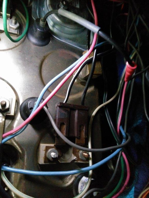
Today I opened up the wiring harness and first found the black wire, with a blue female connector attached. Opened the harness some more and found the red wire going to the starter that clearly was fused together with the yellow connector you see.
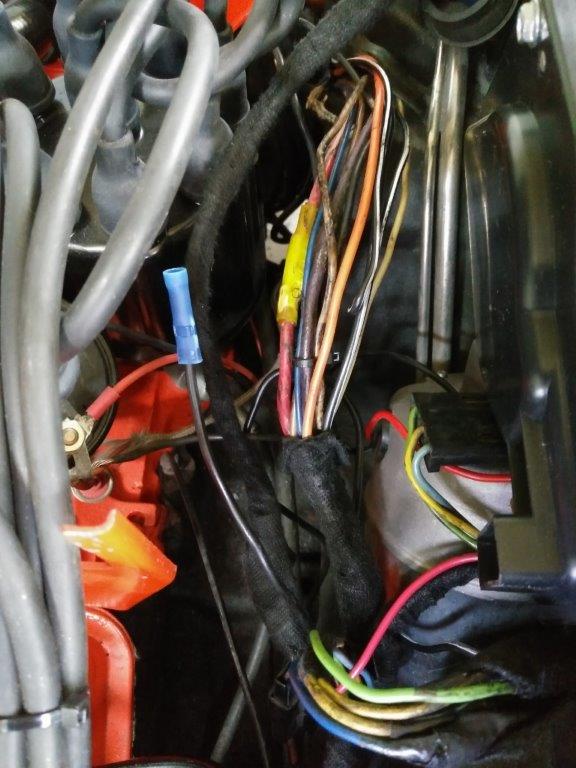
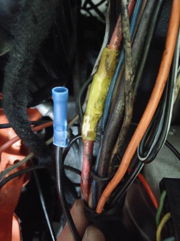
Thanks for all your help so far!
Now I would ideally find a pigtail that is cut from an original harness, with the 2 red wires, the black wire and the fusible link in between. That would be the easiest to install, given the difference in wire sizes... If anyone has this and wants to sell, I'm interested!
02-13-2018, 04:36 PM
#10
Pro
Check on the forum under parts. Should be lots around. I bough one off a member. You can make you own as well. A fusible link has the wire 4 wire sizes smaller so if the red is a #10 then you put in a #14 wire. Too much current will burn the smaller wire quicker than larger.
Looks way better with a original though. If you find one use heat shrink and solder the wires together to repair to eliminate voltage drops as it is your ammeter circuit. Congrats on finding your problem
Looks way better with a original though. If you find one use heat shrink and solder the wires together to repair to eliminate voltage drops as it is your ammeter circuit. Congrats on finding your problem
02-13-2018, 10:17 PM
#11
Le Mans Master
Member Since: Aug 2006
Location: mount holly NC
Posts: 6,985
Received 1,244 Likes
on
965 Posts
C3 of Year Finalist (appearance mods) 2019
Your thumbs now face away from each other.
Now bring your hands together as if to pray.
Now all the fingers match.
The bulkhead connectors show left and right if you bring them together they match.
Let's say you follow a wire to the LEFT top dot, the wire exits the other half at the top RIGHT.
The following users liked this post:
GKO777 (02-14-2018)
02-14-2018, 07:11 AM
#12
Instructor
Thread Starter
Put both your hands in front of you with the palms up.
Your thumbs now face away from each other.
Now bring your hands together as if to pray.
Now all the fingers match.
The bulkhead connectors show left and right if you bring them together they match.
Let's say you follow a wire to the LEFT top dot, the wire exits the other half at the top RIGHT.
Your thumbs now face away from each other.
Now bring your hands together as if to pray.
Now all the fingers match.
The bulkhead connectors show left and right if you bring them together they match.
Let's say you follow a wire to the LEFT top dot, the wire exits the other half at the top RIGHT.
02-14-2018, 07:23 AM
#13
Team Owner

The ammeter leads are both connected to the same power wire in the harness. But, they are connected at a fixed distance apart (around 12" or so). That length of wire between them acts as a 'current shunt' and produces a voltage drop which is proportional to the current flowing in that wire. The small voltage drop on that length of wire is sent to the ammeter which is scaled to read "AMPS".
Although that sounds complicated, the wiring is very simple: two ammeter leads run to one [main] power wire and attached at a fixed distance apart.
You cannot run those ammeter leads to ANY location on that wire or at a terminal connector and get the ammeter to read correctly. They must tie into that power lead at specific locations for the ammeter to be calibrated properly.
Last edited by 7T1vette; 02-14-2018 at 07:23 AM.
The following users liked this post:
wadenelson (08-20-2021)
02-14-2018, 07:44 AM
#15
Instructor
Thread Starter
The ammeter leads are both connected to the same power wire in the harness. But, they are connected at a fixed distance apart (around 12" or so). That length of wire between them acts as a 'current shunt' and produces a voltage drop which is proportional to the current flowing in that wire. The small voltage drop on that length of wire is sent to the ammeter which is scaled to read "AMPS".
Although that sounds complicated, the wiring is very simple: two ammeter leads run to one [main] power wire and attached at a fixed distance apart.
You cannot run those ammeter leads to ANY location on that wire or at a terminal connector and get the ammeter to read correctly. They must tie into that power lead at specific locations for the ammeter to be calibrated properly.
Although that sounds complicated, the wiring is very simple: two ammeter leads run to one [main] power wire and attached at a fixed distance apart.
You cannot run those ammeter leads to ANY location on that wire or at a terminal connector and get the ammeter to read correctly. They must tie into that power lead at specific locations for the ammeter to be calibrated properly.
Now just see if I can buy the original pigtail from someone with the fusible link still in place...
02-15-2018, 01:25 PM
#17
Instructor
Thread Starter
One last question: the brown connector seems to fit both ways on the ammeter. In the first picture you can see how it is connected now (B/W wire to the bottom of the cluster, Black to the top), but I saw another picture on this forum where the the connector seemed fitted the other way around.
I have to close the dash up again before I can test (I don't have the fusible link yet), so I want to have it connected the right way...
I have to close the dash up again before I can test (I don't have the fusible link yet), so I want to have it connected the right way...
02-15-2018, 01:37 PM
#18
Le Mans Master
Member Since: Aug 2006
Location: mount holly NC
Posts: 6,985
Received 1,244 Likes
on
965 Posts
C3 of Year Finalist (appearance mods) 2019
One last question: the brown connector seems to fit both ways on the ammeter. In the first picture you can see how it is connected now (B/W wire to the bottom of the cluster, Black to the top), but I saw another picture on this forum where the the connector seemed fitted the other way around.
I have to close the dash up again before I can test (I don't have the fusible link yet), so I want to have it connected the right way...
I have to close the dash up again before I can test (I don't have the fusible link yet), so I want to have it connected the right way...

 02-15-2018, 05:17 PM
#20
Melting Slicks


there should be a couple of dimples on the spade terminals, these go on the open side of the plastic connector, to fit on easily, that is why they make it that way.

