
How are you wiring your Dewitt's SPAL Fans?
 09-17-2006, 11:42 PM
#1
Instructor

Thread Starter

Member Since: Jan 2005
Location: Formerly DFW Missing Texas Now in NJ
Posts: 162
Likes: 0
Received 0 Likes
on
0 Posts

I'm almost done getting the whole car back together. Today was SPAL fan day...
I bought the Dewitt's Dual SPAL Fan package. I like the radiator I bought from Dewitt's earlier and figured my best bet was to stick with them for the fans too.
The fans mount up great. I had a little trouble with positioning them. I centered them on the radiator at first but they hit the upper A Arm on the drivers side. I moved them over 3/4 of an inch and they fit great now.
Wiring the fans up has been something of a challenge. The diagrams are straight forward but my brain hurt trying to figure it all out. Although that's probably just me.
The questions I have are related to the wiring
1) Fuse - The kit came with two fuses. Essentially they were one wire in a ring back into the fuse. I'm assuming the red wire gets cut so you can run this in-line. It was a bit strange the way they came. Am I right?
2) Switched Power/Power From Ignition - The relays each have an orange wire that I assume controls power to the fans when the ignition is on. The instructions say connect these wires to a power source controlled from the ignition if you want the fans only to run when the car is on. Or you can run the orange wires to a constant power source and the fans will run whenever the engine exceeds the temperature setting.
For now I have the orange wires run to the horn relay which is constant power. I figure in Texas this isn't such a bad idea as the fans will keep the motor from heating up after it's turned off. (It's been over 106 degrees here the last few weeks.)
However, this is also a great way to drain the battery when I'm not paying attention. What source do you use for the Switched/Ignition controlled power for these orange wires? I've gone through the wiring diagram and I'm at a loss for the best place in the engine compartment to wire them.
3) Ground! - The SPAL controller has two wires 1 black and 1 white that need ground and the second fan has a black wire that needs ground. The relay does not have a separate ground. Where do you guys ground these wires? I'm thinking of drilling a hole in the frame and bolting them all together to this point. I was going to use the alternator but the ground bolt stripped the threads in the new alternator (well I did, not the bolt) and I was able to get the wires that are supposed to go there connected. I don't want to tempt fate adding the fan wires to the alternator. There is a small threaded hole on the block just above the motor mount on the driver side but I'm afraid to run the wires between/close to the headers.
Any suggestions on a good grounding point would be appreciated.
4) Temperature sensor - I installed the temp sender that came with the kit to the passenger head location between cylinders 6-8. The gauge sending unit that I ordered is too big for the Vortec heads so I put it in the rear hole on the intake. I'm hoping this will be OK. I'm thinking this area will be 10-15 degrees cooler than the head so the gauge will be lower than the actual temp. I'm also assuming the aluminum intake will be adequate ground.
5) Really dumb question - Is chrome an acceptable conductor of electricity? Can I ground something to a chrome bracket? (I'm assuming yes. I'm not sure why this isn't obvious to me.)
Thanks in advance.
Whiplash
I bought the Dewitt's Dual SPAL Fan package. I like the radiator I bought from Dewitt's earlier and figured my best bet was to stick with them for the fans too.
The fans mount up great. I had a little trouble with positioning them. I centered them on the radiator at first but they hit the upper A Arm on the drivers side. I moved them over 3/4 of an inch and they fit great now.
Wiring the fans up has been something of a challenge. The diagrams are straight forward but my brain hurt trying to figure it all out.
Although that's probably just me.The questions I have are related to the wiring
1) Fuse - The kit came with two fuses. Essentially they were one wire in a ring back into the fuse. I'm assuming the red wire gets cut so you can run this in-line. It was a bit strange the way they came. Am I right?
2) Switched Power/Power From Ignition - The relays each have an orange wire that I assume controls power to the fans when the ignition is on. The instructions say connect these wires to a power source controlled from the ignition if you want the fans only to run when the car is on. Or you can run the orange wires to a constant power source and the fans will run whenever the engine exceeds the temperature setting.
For now I have the orange wires run to the horn relay which is constant power. I figure in Texas this isn't such a bad idea as the fans will keep the motor from heating up after it's turned off. (It's been over 106 degrees here the last few weeks.)
However, this is also a great way to drain the battery when I'm not paying attention. What source do you use for the Switched/Ignition controlled power for these orange wires? I've gone through the wiring diagram and I'm at a loss for the best place in the engine compartment to wire them.
3) Ground! - The SPAL controller has two wires 1 black and 1 white that need ground and the second fan has a black wire that needs ground. The relay does not have a separate ground. Where do you guys ground these wires? I'm thinking of drilling a hole in the frame and bolting them all together to this point. I was going to use the alternator but the ground bolt stripped the threads in the new alternator (well I did, not the bolt) and I was able to get the wires that are supposed to go there connected. I don't want to tempt fate adding the fan wires to the alternator. There is a small threaded hole on the block just above the motor mount on the driver side but I'm afraid to run the wires between/close to the headers.
Any suggestions on a good grounding point would be appreciated.
4) Temperature sensor - I installed the temp sender that came with the kit to the passenger head location between cylinders 6-8. The gauge sending unit that I ordered is too big for the Vortec heads so I put it in the rear hole on the intake. I'm hoping this will be OK. I'm thinking this area will be 10-15 degrees cooler than the head so the gauge will be lower than the actual temp. I'm also assuming the aluminum intake will be adequate ground.
5) Really dumb question - Is chrome an acceptable conductor of electricity? Can I ground something to a chrome bracket? (I'm assuming yes. I'm not sure why this isn't obvious to me.)
Thanks in advance.
Whiplash
Last edited by Whiplash71; 09-17-2006 at 11:56 PM.
 09-18-2006, 08:30 AM
#2
Melting Slicks

Originally Posted by Whiplash71
1) Fuse - The kit came with two fuses. Essentially they were one wire in a ring back into the fuse. I'm assuming the red wire gets cut so you can run this in-line. It was a bit strange the way they came. Am I right?
2) Switched Power/Power From Ignition - The relays each have an orange wire that I assume controls power to the fans when the ignition is on. The instructions say connect these wires to a power source controlled from the ignition if you want the fans only to run when the car is on. Or you can run the orange wires to a constant power source and the fans will run whenever the engine exceeds the temperature setting.
For now I have the orange wires run to the horn relay which is constant power. I figure in Texas this isn't such a bad idea as the fans will keep the motor from heating up after it's turned off. (It's been over 106 degrees here the last few weeks.)
However, this is also a great way to drain the battery when I'm not paying attention. What source do you use for the Switched/Ignition controlled power for these orange wires? I've gone through the wiring diagram and I'm at a loss for the best place in the engine compartment to wire them.
3) Ground! - The SPAL controller has two wires 1 black and 1 white that need ground and the second fan has a black wire that needs ground. The relay does not have a separate ground. Where do you guys ground these wires? I'm thinking of drilling a hole in the frame and bolting them all together to this point. I was going to use the alternator but the ground bolt stripped the threads in the new alternator (well I did, not the bolt) and I was able to get the wires that are supposed to go there connected. I don't want to tempt fate adding the fan wires to the alternator. There is a small threaded hole on the block just above the motor mount on the driver side but I'm afraid to run the wires between/close to the headers.
Any suggestions on a good grounding point would be appreciated.
Any suggestions on a good grounding point would be appreciated.
4) Temperature sensor - I installed the temp sender that came with the kit to the passenger head location between cylinders 6-8. The gauge sending unit that I ordered is too big for the Vortec heads so I put it in the rear hole on the intake. I'm hoping this will be OK. I'm thinking this area will be 10-15 degrees cooler than the head so the gauge will be lower than the actual temp. I'm also assuming the aluminum intake will be adequate ground.
5) Really dumb question - Is chrome an acceptable conductor of electricity? Can I ground something to a chrome bracket? (I'm assuming yes. I'm not sure why this isn't obvious to me.)
Thanks in advance.
Whiplash
Whiplash
Here are some pics...
Relay for the second fan

A view of all of the electrical components and connections for the Controller and Fans

The Junction is wired to the Horn Relay which is fed from the Alternator (you can see the additional 8 gauge wire in the last picture)

All "High Drain" components now connect here

"Plug and Play" sensor

Here you can see the feed for the Horn Relay/Junction integrated into the stock wiring boot and harness
 09-18-2006, 09:02 AM
#3
Burning Brakes


 PWS69 is telling you right on all the above. I had a lot going on in the area of my fan controller. I added headlight relays in the same area and had several things that needed ground so I ran one heavy (10gauge) ground from the engine to a stud that I mounted to the inner fender. This gave me a good ground at a close location for all my accessories. The SPAL controller seems to be very sensative to electrical spikes so a good ground and power supply will save you some headaches. This is how I located mine but I used man reset circuit breakers rather than the included fuses.
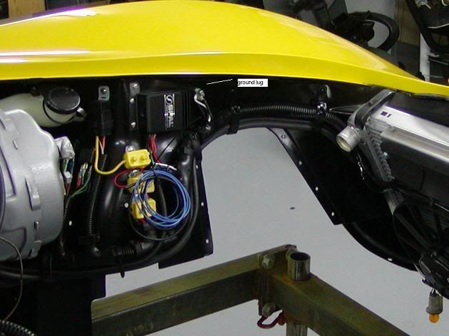 09-18-2006, 09:07 AM
#4
everything that pws69 said; a couple of adders:2) consider using the ACC terminal vs IGN terminal. that way the fans won't try to run when cranking the engine
3) all that electrical power has to make it's way to/from the battery. conecting the ground to the ALT means it has to travel through a 12 ga wire (i think 12 ga), through the harness to the connection at the drivers side lower front rad support; not good. better: run new wires to same ground and hide in harness, or find other ground that suits your appearance goals without overloading wiring.
09-18-2006, 09:44 AM
#6
Burning Brakes
One more thing, If you are having trouble with the SPAL temp sensor you can use the sending unit that is already there for your gauge. I had trouble with my sending unit working right (later discovered that I had a bent pin on the sensor), anyway, I used the OEM sending unit and reprogrammed the speed controller. It wasn't hard and it works great. Others have posted about having trouble with this but I'm not too sure that a lot of the problems are electrical installation problems. The SPAL sensor has its own ground while the OEM sending unit grounds through the eng block. I mentioned earlier that I had grounded everything back to the engine. This was a convient place for me to get a good ground but I know for a fact that I have a new battery cable sized jumper from my frame to the eng. with good clean connections. I have a new #10 power wire from my alt. post to power my accessories and the alt. grounds to the eng block. so this appeared to me that it would provide the best isolation from other electrical equip.
If you have any problems I would check my grounding straps, cables first.
If you have any problems I would check my grounding straps, cables first.
09-18-2006, 09:52 AM
#7
Xakk: Based on advice from Tom, I ran mine to the starter for power.
-heads-up for those who have a shunt ammeter with one end connected to bus and other to starter: doing this will cause the current used by whatever is connected to the starter to be added to the charging current indicated on the ammeter. it appears that the factory ammeter was originally wired to see only the charging current. it will work, but as long as you know . . . those without shunt ammeter, disregard
thanks
09-18-2006, 10:55 AM
#8
Safety Car

Member Since: Aug 2001
Location: North Easton Mass
Posts: 4,883
Likes: 0
Received 8 Likes
on
8 Posts

Originally Posted by Whiplash71
I'm almost done getting the whole car back together. Today was SPAL fan day...
I bought the Dewitt's Dual SPAL Fan package. I like the radiator I bought from Dewitt's earlier and figured my best bet was to stick with them for the fans too.
The fans mount up great. I had a little trouble with positioning them. I centered them on the radiator at first but they hit the upper A Arm on the drivers side. I moved them over 3/4 of an inch and they fit great now.
Wiring the fans up has been something of a challenge. The diagrams are straight forward but my brain hurt trying to figure it all out. Although that's probably just me.
The questions I have are related to the wiring
1) Fuse - The kit came with two fuses. Essentially they were one wire in a ring back into the fuse. I'm assuming the red wire gets cut so you can run this in-line. It was a bit strange the way they came. Am I right?
2) Switched Power/Power From Ignition - The relays each have an orange wire that I assume controls power to the fans when the ignition is on. The instructions say connect these wires to a power source controlled from the ignition if you want the fans only to run when the car is on. Or you can run the orange wires to a constant power source and the fans will run whenever the engine exceeds the temperature setting.
For now I have the orange wires run to the horn relay which is constant power. I figure in Texas this isn't such a bad idea as the fans will keep the motor from heating up after it's turned off. (It's been over 106 degrees here the last few weeks.)
However, this is also a great way to drain the battery when I'm not paying attention. What source do you use for the Switched/Ignition controlled power for these orange wires? I've gone through the wiring diagram and I'm at a loss for the best place in the engine compartment to wire them.
3) Ground! - The SPAL controller has two wires 1 black and 1 white that need ground and the second fan has a black wire that needs ground. The relay does not have a separate ground. Where do you guys ground these wires? I'm thinking of drilling a hole in the frame and bolting them all together to this point. I was going to use the alternator but the ground bolt stripped the threads in the new alternator (well I did, not the bolt) and I was able to get the wires that are supposed to go there connected. I don't want to tempt fate adding the fan wires to the alternator. There is a small threaded hole on the block just above the motor mount on the driver side but I'm afraid to run the wires between/close to the headers.
Any suggestions on a good grounding point would be appreciated.
4) Temperature sensor - I installed the temp sender that came with the kit to the passenger head location between cylinders 6-8. The gauge sending unit that I ordered is too big for the Vortec heads so I put it in the rear hole on the intake. I'm hoping this will be OK. I'm thinking this area will be 10-15 degrees cooler than the head so the gauge will be lower than the actual temp. I'm also assuming the aluminum intake will be adequate ground.
5) Really dumb question - Is chrome an acceptable conductor of electricity? Can I ground something to a chrome bracket? (I'm assuming yes. I'm not sure why this isn't obvious to me.)
Thanks in advance.
Whiplash
I bought the Dewitt's Dual SPAL Fan package. I like the radiator I bought from Dewitt's earlier and figured my best bet was to stick with them for the fans too.
The fans mount up great. I had a little trouble with positioning them. I centered them on the radiator at first but they hit the upper A Arm on the drivers side. I moved them over 3/4 of an inch and they fit great now.
Wiring the fans up has been something of a challenge. The diagrams are straight forward but my brain hurt trying to figure it all out.
Although that's probably just me.The questions I have are related to the wiring
1) Fuse - The kit came with two fuses. Essentially they were one wire in a ring back into the fuse. I'm assuming the red wire gets cut so you can run this in-line. It was a bit strange the way they came. Am I right?
2) Switched Power/Power From Ignition - The relays each have an orange wire that I assume controls power to the fans when the ignition is on. The instructions say connect these wires to a power source controlled from the ignition if you want the fans only to run when the car is on. Or you can run the orange wires to a constant power source and the fans will run whenever the engine exceeds the temperature setting.
For now I have the orange wires run to the horn relay which is constant power. I figure in Texas this isn't such a bad idea as the fans will keep the motor from heating up after it's turned off. (It's been over 106 degrees here the last few weeks.)
However, this is also a great way to drain the battery when I'm not paying attention. What source do you use for the Switched/Ignition controlled power for these orange wires? I've gone through the wiring diagram and I'm at a loss for the best place in the engine compartment to wire them.
3) Ground! - The SPAL controller has two wires 1 black and 1 white that need ground and the second fan has a black wire that needs ground. The relay does not have a separate ground. Where do you guys ground these wires? I'm thinking of drilling a hole in the frame and bolting them all together to this point. I was going to use the alternator but the ground bolt stripped the threads in the new alternator (well I did, not the bolt) and I was able to get the wires that are supposed to go there connected. I don't want to tempt fate adding the fan wires to the alternator. There is a small threaded hole on the block just above the motor mount on the driver side but I'm afraid to run the wires between/close to the headers.
Any suggestions on a good grounding point would be appreciated.
4) Temperature sensor - I installed the temp sender that came with the kit to the passenger head location between cylinders 6-8. The gauge sending unit that I ordered is too big for the Vortec heads so I put it in the rear hole on the intake. I'm hoping this will be OK. I'm thinking this area will be 10-15 degrees cooler than the head so the gauge will be lower than the actual temp. I'm also assuming the aluminum intake will be adequate ground.
5) Really dumb question - Is chrome an acceptable conductor of electricity? Can I ground something to a chrome bracket? (I'm assuming yes. I'm not sure why this isn't obvious to me.)
Thanks in advance.
Whiplash
1. Yes, you do cut the red wire to the fuse holder so it can be connected inline. The fuse that you need depends on the model fan you are using. If you put in a 20 amp fuse and it blows the first time the fan turns on switch to the 30 amp fuse.
3. You can wire the grounds to the frame. Just make sure you clean the contact area with something abrasive so that you make good contact. I connected the controller power and main ground wires to the battery connections at the starter and frame. I gounded the white wire to one of the fuel line clips.
If you ground the second fan to the frame, check the resistance between it's ground point and the main ground. There should be only single ohms of resistance at most.
I'm only using a single fan so I'll leave the discussion of relay hookups to others. Good luck with the installation.

Rick B.
09-18-2006, 11:12 AM
#9
Melting Slicks
S489:
2) consider using the ACC terminal vs IGN terminal. that way the fans won't try to run when cranking the engine
2) consider using the ACC terminal vs IGN terminal. that way the fans won't try to run when cranking the engine
3) all that electrical power has to make it's way to/from the battery. conecting the ground to the ALT means it has to travel through a 12 ga wire (i think 12 ga), through the harness to the connection at the drivers side lower front rad support; not good. better: run new wires to same ground and hide in harness, or find other ground that suits your appearance goals without overloading wiring.
General:
Everybody has mentioned grounding - and for good reason. It is probably the most overlooked potential for problems. Most say to go to the block - which is a good point AS LONG AS THE ENGINE IS SUFFICIENTLY GROUNDED. Don't forget that, in our beasts, the battery ground attaches to the FRAME - not the engine. It is EXTREMELY important that you have a good, solid ground connection from the frame to the battery AND to the motor. I have a 0 gauge cable (not a strap) bolted to the engine and frame to ensure there is essentially 0 voltage differential between the frame and the engine.
And finally, if you are not aware of them, MAD Electronics has some excellent information on upgrading Chevy electrical systems that you can use a a reference for any part of this that may be unclear or confusing.
09-18-2006, 12:45 PM
#10
Race Director

Originally Posted by pws69
Everybody has mentioned grounding - and for good reason. It is probably the most overlooked potential for problems. Most say to go to the block - which is a good point AS LONG AS THE ENGINE IS SUFFICIENTLY GROUNDED. Don't forget that, in our beasts, the battery ground attaches to the FRAME - not the engine. It is EXTREMELY important that you have a good, solid ground connection from the frame to the battery AND to the motor. I have a 0 gauge cable (not a strap) bolted to the engine and frame to ensure there is essentially 0 voltage differential between the frame and the engine.
I have my ground hooked to the bellhousing bolt. It is also the ground for my ignition box. I run a heavy cable from the engine to the frame also. Never had a ground problem. I also run my power lines right from the starter lug tha tthe positive battery cable is attached to. This gives me direct power.
09-18-2006, 02:05 PM
#11
Instructor
Thread Starter
Member Since: Jan 2005
Location: Formerly DFW Missing Texas Now in NJ
Posts: 162
Likes: 0
Received 0 Likes
on
0 Posts
[QUOTE=pws69]
I ran a wire back into the fuse panel and plugged into the IGN terminal. I don't believe this is fused so you might want to put one inline or out near the other fuses.
The Junction is wired to the Horn Relay which is fed from the Alternator (you can see the additional 8 gauge wire in the last picture)
All "High Drain" components now connect here
QUOTE]
IGN or ACC it is thanks!
I'll ground everything to the frame. The ground that goes to the radiator support concerns me as the entire frame and support were painted. When I put them back together I'm not sure they ever made a metal to metal connection. I'm going to run this ground back to the same point that I ground the fans too.
Where did you get that junction? I tried an Orielly at lunch and they didn't have a clue. The wiring at the horn relay is a bit jumbled and this would certainly clean things up.
Thanks!
09-18-2006, 02:39 PM
#12
Melting Slicks
Originally Posted by Whiplash71
Where did you get that junction? I tried an Orielly at lunch and they didn't have a clue. The wiring at the horn relay is a bit jumbled and this would certainly clean things up.
Thanks!
They have very high quality products at very good prices. Also excellent support if you have questions.
Last edited by pws69; 09-18-2006 at 02:50 PM.
09-18-2006, 07:33 PM
#13


Nice job guys as an electrcian I try to do the best wiring I can neat being # 1, sometimes I get side tracked on over kill, and over the obivous places get power and what not!!