
SI alternator wiring question on 74
 12-17-2013, 10:39 PM
#1
Drifting

Thread Starter

Gentlemen,
Im having a hard time deciphering wiring diagrams. I am working on the voltage regulator two prong connector on the alternator and the main power-up wire to the dash.
Question 1. My Limited Lectric wiring diagram for 74 seems to be missing the brown wire that connects to the #1 pin (field) on the alternator (pen point to finger tip). Where does that wire actually go? What does it do?
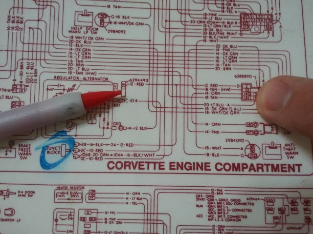
Question 2. This diagram kinda shows what I have now. I am trying to clean up the "nasty splice". I added a red line in to show the current #2 (sensing) wire that attaches to a splice between the junction block and the dash power wire.
What would happen if I ran the #2 sensing wire to the junction block, instead of that splice into the main power up wire? (dash line)
Thank you,
John

***Update***
I got Mark from MADelectrical.com on the phone and he recommend to go ahead and delete the splice and run the main power and fusible link to the terminal block and a separate wire from the voltage sensing pin on the alternator to the terminal block.
Im having a hard time deciphering wiring diagrams. I am working on the voltage regulator two prong connector on the alternator and the main power-up wire to the dash.
Question 1. My Limited Lectric wiring diagram for 74 seems to be missing the brown wire that connects to the #1 pin (field) on the alternator (pen point to finger tip). Where does that wire actually go? What does it do?
Question 2. This diagram kinda shows what I have now. I am trying to clean up the "nasty splice". I added a red line in to show the current #2 (sensing) wire that attaches to a splice between the junction block and the dash power wire.
What would happen if I ran the #2 sensing wire to the junction block, instead of that splice into the main power up wire? (dash line)
Thank you,
John
***Update***
I got Mark from MADelectrical.com on the phone and he recommend to go ahead and delete the splice and run the main power and fusible link to the terminal block and a separate wire from the voltage sensing pin on the alternator to the terminal block.
Last edited by johnt365; 12-18-2013 at 10:45 PM.
 12-19-2013, 03:17 PM
#2

 12-19-2013, 06:23 PM
#3
Melting Slicks


Think of it as a switch that "turns the alternator on"
Question 2. This diagram kinda shows what I have now. I am trying to clean up the "nasty splice". I added a red line in to show the current #2 (sensing) wire that attaches to a splice between the junction block and the dash power wire.
What would happen if I ran the #2 sensing wire to the junction block, instead of that splice into the main power up wire? (dash line)
Interesting that the wire is missing from the harness - perhaps ordered for a "1 wire" alternator (I have no idea if Lectric Limited offers that - or assumes it!!)
.
Last edited by pws69; 12-19-2013 at 06:33 PM.