When you click on links to various merchants on this site and make a purchase, this can result in this site earning a commission. Affiliate programs and affiliations include, but are not limited to, the eBay Partner Network.
Did I mention the pump cost me $30 at the pick and pull and included the connectors and shock mounts? When I told the guy it was for a project, he cut me a deal.
I just swapped the regulator in my alternator from 4 pin to 2 pin, so now it's like a 2006 or newer alternator. Why??? Because GM thinks it's better than the older 4 pin one and they must know something.
Oh but everyone says you need a late model 2006+ ECM/BCM to run it or it only gives you 13.7 volts. Not necessarily.
Here's the secret why GM puts it in later model cars. The computer can command the alternator to put out any voltage from 11V to 15.5V.
Before the late model engine is started, and also after its shut off, GM can check the condition of your battery. Then they can decide how to charge it and they command the alternator to put out the voltage needed to maintain the battery. Also, the alternator tells the computer if it's having trouble putting out the voltage that the computer commanded. To help the alternator, the computer might raise the idle speed for example.
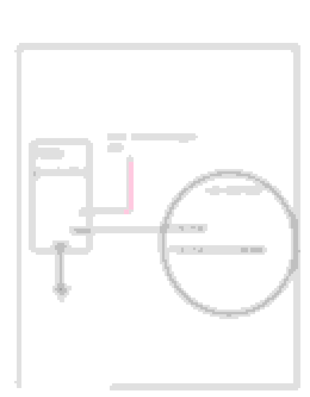
The L pin is the command voltage pin. A 5V PWM signal is sent from the ECM/BCM at a frequency of 128hz. If the duty cycle is less than 10% or more than 90% or just plain not connected, the alternator will go into default mode and put out about 13.7 volts. Enough to keep your car running, but not enough to charge the battery well. Here are the voltages and duty cycles:
10% = 11.0 V
20% = 11.56 V
30% = 12.12 V
40% = 12.68 V
50% = 13.25 V
60% = 13.81 V
70% = 14.37 V
80% = 14.94 V
90% = 15.5 V
The F terminal is also a PWM signal. But it's put out by the alternator and read by the computer. The lower the duty cycle the easier the alternator is working. If you want to use the alternator and aren't connected to the correct ECM/BCM then you don't need to connect the F terminal.
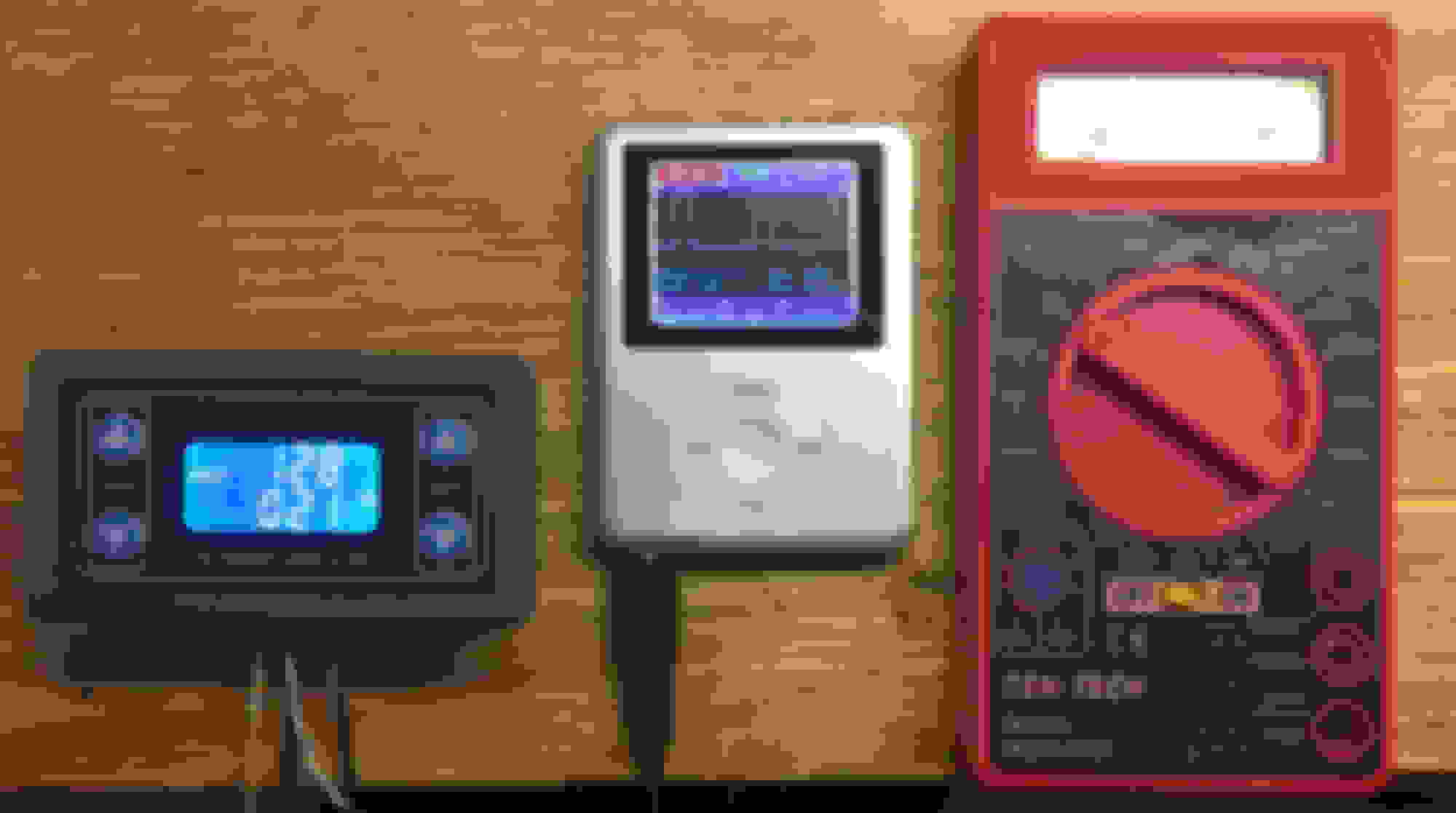
It remembers the last setting even after it's turned off so once you set it, that's where it will stay. Set the frequency to 128 and then set the duty cycle to whatever voltage you want the alternator to put out. Let's say you're at the track and you want a little more voltage for you fuel pump and coils. Easy. Just raise the duty cycle. Or you left the lights on and your battery is low.... Easy.
Here's how you wire it:
Ignore the Power input -. Apply 5V to the Power input + terminal. You can probably use the 5V signal from the ECM. The PWM controller takes very little power. Connect the ground to signal ground and connect the PWM out to the L terminal of the alternator.
Now go pull that 2 pin alternator out of the trash bin.
Ok, I don't need to use that PWM controller in my Vette. Instead, I PWM it directly from my DIY transmission/car controller. I can command the alternator not to do any work till a few seconds after the car started and then slowly ramp up the voltage to normal levels. I may also measure the batteries voltage before the engine starts and increase the charge for a while if it was low.
Over the past 2 years, I've completely redesigned the DIY 4L80E controller and body module.
The first version was based on an Arduino Due processor board and LCD display. The reason I used the Due was because it was blazing fast. But it had some down sides as well. These down sides included inconsistent power up, 3.3v instead of 5 volt operation and no built in NVRAM (can't store settings when powered off). I worked around these and got it to work, but I wasn't happy with it and the display sucked.
The new (final) version is based on the Arduino Mega board. As it turns out, the Mega is more than plenty fast enough for the task. It's a 5 volt board, so no jumping through hoops to interface it. It can store and retrieve settings after being powered off. Has lots of I/O pins to connect to the rest of the world.
Here is some of the basic functionality:
It controls the 4l80E
PWMs all the fans: 2 radiator, 2 intercooler, trans cooler and oil cooler
PWMs the two fuel pumps
PWMs the alternator
Connects to the AEM infinity with CANBUS
Controls Boost
Controls the BOV
Displays alarms from AEM or itself.
Triggers the AEM two step
Controls the backup lights
Controls the brake lights
Scramble button
Fuel level sensor
Paddle shifting input
Line pressure input
4L80E temperature input
7" touch screen display and control center
I don't plan on having any gauges in the Vette. The touch screen I designed has more than I need to use this car as both a cruiser and strip car.
This is the display/control with the 6.0 running. This is not the final enclosure, just something I 3D printed.
The Vette can be operated in a bunch of different modes. Each mode has it's own shift logic, shift points, boost in each gear and display screens.
This is cruise mode. Automatic upshifting and downshifting is based on load and MPH or optional paddle shift. Cruise mode and be switched to sport mode which is like cruise mode, but with higher shift points and more boost per gear.
Each mode has many nuances and rules. For example burnout mode can be locked out if the shifter is not in 3. shifting is triggered by RPM only. It only shifts from first to second and has it's own set of boost levels for each gear. When the MPH comes back down at the end of the burnout, it automatically changes to drag mode.
Upshifts are by RPM and only go to 3rd gear. No lockup. Downshifts are normal.
Two step is automatically turned on at launch time and automatically turned off when the brake pressure is reduced past a set point. I might implement a "Sloppy Brake" when the two step is on.
Drag mode is locked out unless shifter is in 3rd.
Boost targets are different for each gear and two step.
Back in the day- we would just put a diode on the exciter wire-it'd drop the voltage about a �V - which tricked the Alternator... The stereo played a few DB louder!!!
I'm busy climbing under my car making sure there are no leaks as I fill it up with fluids... I'd rather be soldering!!!
Richard and Rod... Thanks, I can almost see the light at end of the tunnel.
Originally Posted by Richard454
Back in the day- we would just put a diode on the exciter wire-it'd drop the voltage about a �V - which tricked the Alternator... The stereo played a few DB louder!!!
Richard
Ah yes, back in the day. Before we had engine management, in my twin turbo, we tricked the map sensor reading with a diode to trick the computer into letting us raise the boost past factory setting. And I built a fuel pressure regulator that raised 3psi of fuel for every psi of boost so we could run bigger injectors and more boost.
Speaking of fooling the alternator, I plan to increase the voltage at high boost to get a little more out of my fuel pump. I may also cut some of the fans at thigh boost to reduce the load. I can't see being in high boost for more than few seconds.
Originally Posted by Richard454
I'm busy climbing under my car making sure there are no leaks as I fill it up with fluids... I'd rather be soldering!!!
Richard
I like soldering as well, but now that I dropped the body to the frame for hopefully the last time, all my soldering will be under the dashboard which I don't look forward to. Gotta tie all my stuff the the original Vette wiring and install the heat/AC.
Built an adapter plate so now my truck, electronic gas pedal mounts to the original gas pedal mounting holes.
Now that the body and chassis are togehter, I hope they will stay that way for a long time. Installed the body with those red poly body mounts.
The original shifter in the Vette was a three speed and was mangled anyway. I adapted an OD shifter from an 85-92 Camaro/Firebird with a 700R4. It took some persuading, but now it shifts the 4l80E in the Vette.
When I bought the Vette project, it came with tons of brand new replacement parts but didn't include a center console. So I'm probably going to make something eventually. I can't stand the cigarette lighter and ashtray anyway, so I'm probably going to replace it with USB charging ports and I'm going to install and inverter and outlet to power a laptop. Funny, there is a brand new gauge panel in the parts boxes, that I'm not going to use.
Made a mount for the slightly modified truck accelerator pedal assembly so it bolts into the original pedal mounting holes in the vette bulkhead.
Installed a line lock.
Installed a Willwood proportioning valve.
Got the all brake lines plumbed in.
Fixed the slop in the steering column. It's a tilt and telescopic one. For the telescopic part, there is a key that slides in a groove and keyway. That's where the slop was. I didn't see any wear on the keyway and groove, but the key was too narrow somehow. So I welded some more material to the key and ground it flat again. Now it has no play.
The interior of the car was red. It's going to be black now. So I'll re-paint the steering column black before it goes back in.
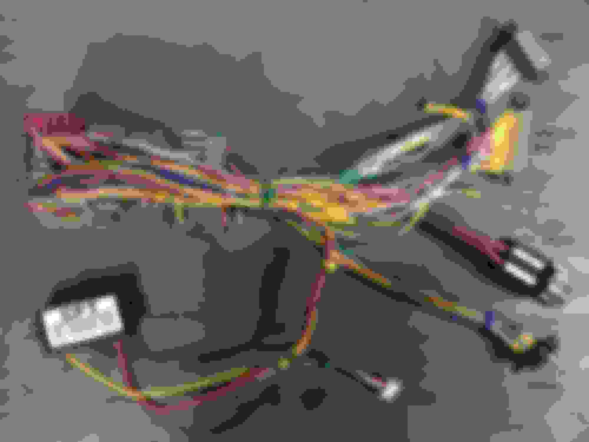
I started to look at combining my wiring and all of the existing wiring. Took some time to label all the existing wires and relays and connectors so I can figure out what gets trashed and what gets left. Willcox had a reasonable schematic of the 77 wiring.
I pulled out all the wiring in passenger area and the steering column so I could eliminate any unnecessary parts and figure out exactly what wire did what so I can merge the original wiring with the new engine and controller wiring. I dragged the whole thing onto a workbench and started testing, tagging and cutting.
The schematic 1977 schematics helped somewhat, but nothing lets you know how stuff works better than testing it.
I used a battery and some lights to let me know exactly what's connected to what and what happens when I turn the ignition key, etc.
I'm going to re-purpose some of the thru firewall wires for whatever I need. Most won't get re-used. I'll reuse some for line lock, underhood courtesy light.....
I got rid of all the instrument lighting, key warning, seat belt warning and a bunch of other stuff I don't need.
I'll tap the key start wire to supply power to the 4l80e neutral safety switch.
I'll tap the ignition on wire to let the AEM know the ignition is on.
I'll tie my chassis ground wire to the few black ground wires that are left.
I'll tie my 12 battery wire to the cluster of red battery power wires.
I'll tie the backup light wire and the brake light wire to something, I have a few choices.
I'll tap the accessory wire for the new radio.
I'm planning on adding remote door locks.
The rest of the lighting circuits will be unchanged. Turn signal lights, overhead courtesy light, exterior lights all as original.
I'm adding a 400 watt A/C inverter with USB ports so I can run a laptop in the car and power the phone chargers. I think I'll power that from the accessory wire. The ashtray and cigarette lighter are gone.
Ran across a problem with the fusebox. I'm really happy I pulled it out or it would have bitten me in the *** later. Turns out some of the contacts for the fuses have some grayish corrosion and the fuse and the terminals don't make contact, even though they look tight. I hate the location of the fusebox anyway so I'm replacing the old fusebox with something a little more modern and relocate it near where the gauges used to be.
I'm going to incorporate the horn relay inside the new fusebox and some other relays I'm adding.
I would have really pulled out what little hair I had left if I hadn't caught this fusebox problem.
Nice- I got rid of the OEM fusebox and OEM horn relay too. The other thing I did was just use the ignition switch to just switch relays- no current at all going through it...Not butt connectors??Carry on!!!

 12-18-2018, 05:08 PM


 sQAAOSwMudblh4p:rk:13:pf:0
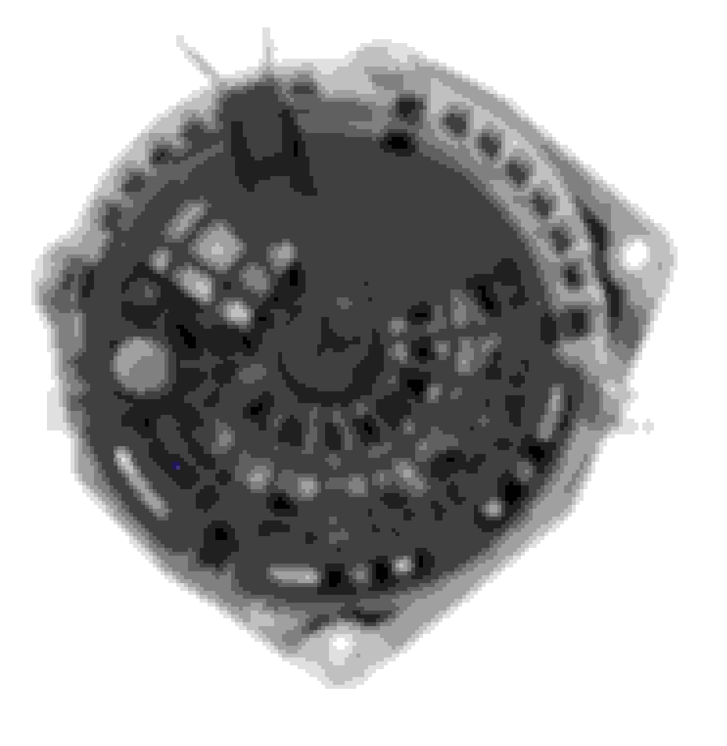


 Carry on!!!
