When you click on links to various merchants on this site and make a purchase, this can result in this site earning a commission. Affiliate programs and affiliations include, but are not limited to, the eBay Partner Network.
Honestly no photo is going to do you any good....or maybe they will.
What you need to do...if I may suggest...it so look at the bulkhead connector on the right side...and compare the terminals that are still in your bulkhead and those that are in the connector you removed. Simple as that.
Thanks but,
I thought it would that easy as well.
But the two different wiring diagrams are different and neither matches
What are in the bulkhead connector on the "right" side.
More than one of the mail pins slide in and out without latching while C3 leads me to think that they have been purposely removed and possibly moved..
Both front marker and turn signals work.. just no headlights that we're working since the green wire came out of the bulkhead and unsure which s the correct "hole" to put it back in
Here are some more photos. The ones with the factory goop are a 68 convertible with manual steering brakes windows and no a/c. The second set with shiny WD40 wash are a second 68 convertible with power brakes, power steering and no a/c. Hope this might help, I am thinking I would take the 68 AIM electrical dwg and a VOM meter and chase all of the wiring out which is a tedious job I know. Not sure why there are 2 different 68 wiring diagram, must have changed during the run. The 68 with the goop is an Oct build and the second is a late Feb build if that helps. Good luck to you. Over 50yrs who know what has been spliced where and how.
Thanks but,
I thought it would that easy as well.
But the two different wiring diagrams are different and neither matches
The bad part is that many wiring diagrams that are GM licensed for reproduction are actuality incorrect from the factory.
Originally Posted by garyguinn
What are in the bulkhead connector on the "right" side.
That usually deals withe ignition for your distributor and your starter and so on.
Look at your wiring diagram and follow the wires and see where they end at . That is how we all learn about this stuff.
Originally Posted by garyguinn
More than one of the mail pins slide in and out without latching while C3 leads me to think that they have been purposely removed and possibly moved..
Yes it is possible and if you post a photo of the terminal that goes into your bulkhead connector. IF it is the correct GM terminal..it can be spread apart and hopefully lock into the connector when ypu push it back in.
Both front marker and turn signals work.. just no headlights that we're working since the green wire came out of the bulkhead and unsure which s the correct "hole" to put it back in[/QUOTE]
The only way to verify that it is the correct 'hole' in the bulk head connector....check on the one mounted in the firewall and if it is... making sense that putting that loose terminal in that hole is correct...because you have another terminal in the firewall side to accept that loose terminal....I would also take my ohmmeter and make sure that the wire in the firewall bulkhead is the wire that I want...because I would check the light green at the high beam /dimmer switch.
Here are some more photos. The ones with the factory goop are a 68 convertible with manual steering brakes windows and no a/c. The second set with shiny WD40 wash are a second 68 convertible with power brakes, power steering and no a/c. Hope this might help, I am thinking I would take the 68 AIM electrical dwg and a VOM meter and chase all of the wiring out which is a tedious job I know. Not sure why there are 2 different 68 wiring diagram, must have changed during the run. The 68 with the goop is an Oct build and the second is a late Feb build if that helps. Good luck to you. Over 50yrs who know what has been spliced where and how.
The bad part is that many wiring diagrams that are GM licensed for reproduction are actuality incorrect from the factory.
That usually deals withe ignition for your distributor and your starter and so on.
(By on the right, i mean looking at the bulkhead from the front.. so the 1/2 of the connector closest to the drivers fender.. if it help, the brake fluid pressure switch is in this half)
Look at your wiring diagram and follow the wires and see where they end at . That is how we all learn about this stuff.
Yes it is possible and if you post a photo of the terminal that goes into your bulkhead connector. IF it is the correct GM terminal..it can be spread apart and hopefully lock into the connector when ypu push it back in.
Both front marker and turn signals work.. just no headlights that we're working since the green wire came out of the bulkhead and unsure which s the correct "hole" to put it back in
The only way to verify that it is the correct 'hole' in the bulk head connector....check on the one mounted in the firewall and if it is... making sense that putting that loose terminal in that hole is correct...because you have another terminal in the firewall side to accept that loose terminal....I would also take my ohmmeter and make sure that the wire in the firewall bulkhead is the wire that I want...because I would check the light green at the high beam /dimmer switch.
DUB[/QUOTE]
Dub, I'll get back out to it tomorrow and see if I can use my meter to trace this down...
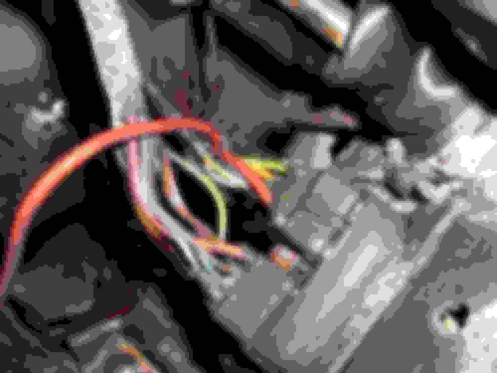
This looks like it..
The light green wire in this picture shows right next to the pink wire.
I have tried the "wayward" wire in this slot but without success..
Is there a fuse that will protect the headlights that possibly blew when the wire came out?
OK...this is going to be a long reply and should do it....or at least how I would do it if your car were in my shop.
With the bulkhead connector attached...I would take my ohmmeter and connect one end to the LIGHT GREEN wire on the dimmer switch..and then go out to my headlights a pull one of the connectors and plug the other end of my ohmmeter in it and see if I have darn near 0 ohms, IF I do...then that is telling me that the wire is continuous and that circuit should be fine....and I wrote SHOULD be fine.
Just because a wire shows continuity or 0 ohms DOES NOT mean that the wire is good...especially IF that wire carries a lot of amps to power up whatever it is going to.
FOR EXAMPLE: IF your battery cable has 200 strands of copper in it to carry the huge load of amps in order to crank your engine, etc....and your battery cable got cut and only ONE strand remained intact. If a person were to check it for continuity it would pass that test..and if they ohmmed out that cable...it would pass that also...BUT when you went to crank the engine...that ONE strand could not handle the amp load and the starter would not work.
So..keep that in mind and that is why many times....depending on whatever it is I am working on...I have a test headlight and other parts (such as a blower motor) that require much higher amp load to run them on harnesses so i can check wires to make sure that they have the integrity needed to work.
Now...if your LIGHT GREEN wire does not show continuity when you have the bulkhead connector connected...you need to remove it and check to make sure the light green wire going to your headlight is good by finding the terminal in the bulkhead connector that you just removed and using your ohmmeter and checking it to one of your headlight bulb connectors. IF that is OK...then that wire should be fine.
NOW...mirror image the location in your firewall connector and going to the dimmer switch...check to make sure that you have close to 0 ohms or continuity.
IF the terminals do not line up...then switch them so they do.
If you put it back together and it is good in regards to ohmming it out...but still does not work.
Then you have to see if you are gettign 12 volts when you turn the headlight switch ON at the dimmer switch and you are checking the YELLOW wire.
IF you are not getting 12 volts....then it can be the 12 gauge RED wire that goes to your headlight switch having an issue.
There is NO fuse for your headlights....it is protected by a fusible link...and more than likely is out by your horn relay...and I might be incorrect on this due to I am not looking at my wiring diagram....but I think I am correct.
4 of the Packard male contacts had been pulled and put back into the
wrong place. in addtition, non were locked into place....
also, all the wires for the wipers had been pulled from the bulkhead connector and left hanging....good grief...
All now rewired correctly, locked into place and working as they should...
I just received Dr Rebuilds color wiring diagram and it helped
verify the correct wiring scheme...
Wow....that wasn't a fun few days...
the help on this forum is amazing...thank you again
Glad you got it repaired...and I run into this from time to time when someone got into an area and screwed it all up.

 10-21-2017, 08:14 PM