When you click on links to various merchants on this site and make a purchase, this can result in this site earning a commission. Affiliate programs and affiliations include, but are not limited to, the eBay Partner Network.
The following is a document I put together while installing my GM TBI system. Hoping it helps anyone wanting to do the same! I'm very pleased with the results, in the tuning process now. Please let me know any areas where details is lacking...
Background
Since buying my 78 last year, I�ve been working on upgrades that would make it a better, more modern vehicle. The best modification I�ve done to date has been installing a TKO600 in place of the original Borg-Warner 4-speed. (post is here: https://www.corvetteforum.com/forums...0-install.html) The overdrive gear makes the car so much more fun to drive on the highways. Since moving to Texas earlier this year, I�ve found that almost every road is 60-70 mph. Great for cruising, but with its 3.73 rear end, my RPMs were up in the 3600 range to do 65. Sounded like the engine was working way too hard. Now it cruises around 1300 RPM.
Next major item I wanted to tackle was the fuel system. I�ve got the original Quadrajet tuned in pretty well � no hesitation, bog, etc. However, I�m guessing one or two plugs are leaking underneath as the float bowls drain down overnight. Lots of cranking to get the car started in the morning, and I don�t like the idea of raw fuel seeping into the cylinders.
I had started a TBI project on an older GMC motorhome a few years back. Sold it before finalizing the install, so I pulled out the harness, sensors, and computer and returned it to stock. I had built a Megasquirt for that application, but have decided for the Corvette to stick with GM products and use one of the original PCMs (more on that to follow).
In addition to the Megasquirt, there are many other very affordable injection options out there. Companies like FiTech revoltionized the industry by coming out with a very affordable option that bolts directly to the manifold, requires very little wiring, and easy to program. Holley and Edelbrock have followed suit. Why did I decide to go with a full GM system?
I love scrounging for parts. A day rooting through a salvage yard is nirvana for me.
Robust and proven design. The throttle body systems are so incredibly simple and the computer modules are rock solid. GM spent millions and millions on R&D, I figured I would piggyback on that.
Spark control. The lowest price option from FiTech (around $700) does not control spark, something that should certainly be taken advantage of when upgrading a system. The more expensive units do.
The challenge of doing it and keeping it looking factory-esque.
While my 78 is an L82, the engine was swapped out some time earlier with a plain-jane Goodwrench 350. Not cranking out big horsepower numbers, but a decent, reliable powerplant. The TBI system will be able to feed it without difficulty, plus provide a foundation for possibly later upgrades to TPI.
The February 2006 issue of Corvette Fever has a good article about doing the same thing, installing a TBI system from junkyard parts. I picked up a copy from eBay, had some really good tips and pictures. They claimed the install was a total of $400. I haven�t tracked every nickle and dime, but that may be close, depending on prices in your area. Of course, the $400 is just for the hardware. If you want to tune and burn your own chips, prices go up. The cheapest setup is a generic programmer (TL866CS) for around $40 on ebay and an adapter and chips from Moates.net. Which adapter depends on the ECM you are using, but plan around $55 with shipping. I found a deal on an Autoprom from Moates that included the adapter and chips, so went that route. New, that setup is around $370.
The CF issue referenced using fuel lines from a 90�s Caprice as they exited in the front near the original, mechanical fuel pump. That tip alone paid for the article. I had previously pulled lines from a Chevy truck (exit in rear and run down trans tunnel) and a third-gen Camaro (exit on driver side). Was planning to do a lot of pipe bending to get the lines in the right place until I read the article. Armed with the Caprice source, I hit a nearby salvage yard that listed inventory including a couple of Caprices. Sure enough, they dump right down where it would be easy to hook into pre-existing lines. I used a set from a 1993 Caprice Classic. There was another Caprice in the older body style that also had similar lines, but a little more crowded engine bay. Unhooked everything from the top, then followed the lines down below. Here I�m hoping I hit paydirt. The Caprice used nylon lines for both return and supply. There were also a series of clever plastic clips that held the lines in place along the frame. I removed all the clips and pulled the lines from all the way back to the tank. Fuel lines were $30, including the fuel filter that I kept for reference purposes. The replacement fuel filter is AC Delco GF580, using the lines from the Caprice. It fits directly into the quick-lock fittings. If you use steel/rubber lines, you�ll need a filter with hose barb ends.
Fuel Lines exiting near original mechanical fuel pump.
Fuel line clamps from the Caprice. Note the black plastic on the upper right. That is a piece of dash I cut from a Chevy pickup for the Check Gauges on the MIL.
The lines from the Caprice route down to near the original, mechanical fuel pump location. However, the lines point forward, where I needed them to point to the rear. Took some tube bending and heat to manipulate the lines. Purchased a tube bender for $25 to help shape the lines into the desired direction. May never use the tool again, but money well spent.
Because 1982 Corvettes were fuel-injected and the fuel sending unit was a drop-in for my 1978, I purchased that for $100 and an AC Delco Fuel Pump (EP241) for $34 on eBay. In addition, I needed to buy an adapter for the wiring harness to mate to the newer, plug-in style fuel pump (AC Delco FP51 - $15 � EDIT: Turned out this purchase was not required. The EP241 kit came with a connector for the new pump). A lower cost option is to use an inline fuel pump mounted on the frame rail, but I decided to keep it as factory as possible. Plus, I wanted to avoid the possibility of hearing the pump running.
I mounted the fuel filter along the frame, just to the rear of the passenger front wheel.
Fuel Filter, supply line from tank on right.
To mate the nylon lines to the fuel sender that uses a hose barb fitting, used a fitting for the plastic lines that is barbed on both ends. However, a 5/16� nylon line is a slightly smaller diameter than a 5/16� rubber line. To fix that, I pressed on a 5/16� nylon line to use as a spacer, then slid the 5/16� rubber line over. Is a tight fit, and with the fuel injection hose clamp, not coming off.
There are a couple of methods to work with the nylon lines and fittings, as they do not press on easily. Wherever possible, I used a set of wood jaws and a vice to hold the line securely, then tapped the fitting in with a driver. This link is to a youtube video that has great detail on the process.
. On the two spliced sections, I used a heat gun set on �Low� for about 90 seconds and pressed on the line.
Although not necessary, I ended up dropping the fuel tank. A prior owner had replaced the fuel tank, and I found that there was no vent provided to release pressure. The original line to the charcoal canister had been removed and a rubber hose was installed in a bung at the top of the tank to act as a vent. However, when I tested the setup in car, there was actual access into the tank. Turned out the bung for the vent was never opened, so the vent hose was not doing anything. Dropped the tank and drilled a 1/16� hole in the base of the bung, then took advantage of the extra space to run the wiring for the fuel pump and route the fuel lines. As easy as it was to drop the tank, I�m glad I did.
(Editor's Note: With the tank out of the way, running the fuel lines was VERY easy. While I'm sure it could be done with the tank in place, it would have to be an extreme exercise in patience).
On a positive note, I got to see these cool markings from the assembly line. Born-On Date?
I went through a couple of different paths on this. I initially planned to use an Edelbrock 2101 with a TransDapt adapter. Unfortunately, the 2101 I bought used was an older model, before Edelbrock made a change to the intake design to allow square bores to be mounted to it. There was interference in the mounting with the holes. The CF article used an intake manifold from a GM truck and it cleared the hood, so I went that route. I paid $30 for the intake at the junkyard. Now need to clean it and make it pretty. Took some scrubbing and soaking in the parts washer, but I'm pleased with the end result.
Manifold as removed from donor vehicle
Manifold after cleaning in the parts washer and starting to prime with High Temp Primer.
Finished, painted with Rustoleum Engine Paint, Aluminum Finish.
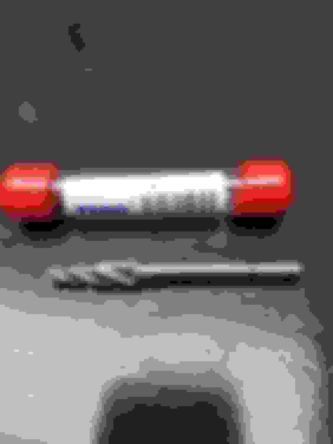
Once cleaned up, the manifold needs to have some slight modifications for the center bolts to fit. Up to 1986, all manifold-to-head bolts were canted at the same angle. From 1986-on, the center bolts were more upright, allowing easier access. To mount the TBI manifold to the pre-1986 heads, the four center bolts must be widened out to the same angle as the other eight bolts. In addition, the pad that the bolt mates to on the manifold needs to be angled to match the new position of the center bolts. There is plenty of material in the area, so just take care and check your work often. The tool I used to modify the manifold is a Temo SL-3 Cone bit and an air grinder. The bit cost $15 on Amazon and did an amazing job. It initially took much longer than I�d hoped, found out later that I�d turned the air pressure down too low on my compressor. Following up the next day with some further trial fitment, breezed right along once I correct the PSI to a little over 40.
SL-3 bit - worked great for widening the center intake bolts and flattening the area to mate with the Goodwrench heads.
Example of flattening required for the bolts to sit flush to the manifold. Nothing here to damage, just don't get too crazy with the bit.
I did lots of trial fitting to minimize the amount of material I removed. The SL-3 bit worked GREAT to trim out the areas.
Bonus pic of my engine with the intake off. Note the ratty valve covers. Those got removed and repainted as part of the project.
One advantage of using the stock TBI manifold is there are a variety of OEM brackets that you can use to fit the sensors and cables. These are plentiful at any junkyard. For the throttle assembly, I ended up using one from the Caprice as it fit most snugly with the cables and external coil. I plan to install a GM cruise control next, so I wanted a bracket that allowed for the cruise cable. Once everything was installed, I had to slightly bend the bracket forward to allow for the correct amount of travel in the throttle cable. As it was initially, the throttle blades on the TBI were just slightly opened.
Because the TBI manifold I pulled came with a function EGR valve, I ended up installing it on the Corvette. I wrestled with this, but decided to keep it as I could always opt later for a block-off plate. The PCM allows better control of the EGR versus the vacuum operated solenoid, and it can always be altered in the tuning to disable its function.
Last part of the fuel system modification was the block-off plate for the mechanical fuel pump. I chose Spectre 42463 for $7 on eBay, lots of other options out there.
One of the major parts you�ll need to change for this to work is swapping out the vacuum-advance HEI or points distributor for one that is computer controlled. I had a good distributor from a 1995 Suburban that I parted out to launch my TBI project a few years ago. It is a small cap distributor, meaning the coil is mounted externally, not housed in the cap like the large cap distributors. Other than swapping out the distributor and coil, not much else needed for Ignition. The only wiring change is to splice the original plug to the HEI that provides battery power and a tach feed to the plug that mates with the distributor.
Mark the ignition wires BEFORE removing the distributor. Trust me, you will be glad you did.
I marked the location of the rotor relative to a fixed spot on the firewall (thankfully it was pointing that way!). Made dropping in the electronic distributor a snap.
From my earlier GMC-intended install, I had an Innovate Motorsports LC-2 Wideband Oxygen sensor. These are pricey, but highly recommended for properly dialing in the tune for your particular engine. I also decided to mount a second, OEM narrowband sensor to talk directly to the PCM. From what I researched online, the while the LC-2 has the ability to mimic a narrowband sensor for the PCM, it doesn�t do it very well. Given I was having one bung installed in the exhaust, I figured a second would not be that much additional cost.
For the narrowband sensor, I am using a Bosch 13077. This is a three-wire, heated sensor. I went that route because � with the headers � the sensor would be further down the exhaust stream and might not get up to temp enough to get into closed loop. Since I was going to be wiring the area anyway, was an easy decision. Picked up the proper connector for $12 of eBay.
Another, while I�m there item for the exhaust was the installation of a new, coated set of Hedman Hedders that came with the car. Long-tube headers would not normally be on my list of things to do, but since they were free, I had a local shop replace the stock manifolds. My reasoning included:
Parts were free, and I was getting really tired of moving the box around the garage
Needed the oxygen sensor bungs welded in
After dialing in the tune for the engine using the stock manifolds, I�d have to dial it in again with the headers
I was going to be working in the engine bay, having to disconnect and reconnect a lot of things. The exhaust-related emissions equipment was crowding the engine bay, making it look cluttered and getting in the way for the injection swap.
As an added benefit, after the headers were installed, the sound of exhaust from the engine was significantly lower. I knew there had been a leak up by the passenger manifold, shop owner confirmed that also several of the AIR tubes were cracked.
Oxygen sensor bung I had welded into the collector on the long tube headers. Matching bung on the driver side unit.
I spent a lot of time thinking about where to locate the PCM, as that would determine everything around wire routing, access holes, etc. I wanted to have relatively easy access to the PCM as � at least during the initial tuning phase � I�d be popping chips in and out a lot. Once the car was up and running, access would not need to be very often. The two areas I considered most was under the radio in the center console and in the rear compartment behind the passenger seat. The rear compartment would provide the easiest access, but a much longer trunk of wires to route through the center console and into the engine bay. The area under the radio would need much less wire work, but I�d have to remove the side panel to the center console each time I needed access to the chip. Turns out all the time I spent thinking about options was completely wasted. Once I removed the center console, it became evident that the only space I had available was the rear compartment. Being an AC car, I had vents blocking any space behind the radio. I could have used the entire glove box space, but didn�t see that as a good tradeoff.
Access through the firewall was drilled just to the right of the support plate for the accelerator pedal. There was enough room for the harness to enter and then tuck into the center console, beneath the radio. I used a universal �� grommet from Home Depot. One tip � keep a light coating of Vasoline on the grommet as you slide the harness through. Will make it much easier and keeps the grommet from popping out. If you are not using a wideband oxygen sensor on your conversion, there is a good chance you can get by with a �� grommet. The cable for the LC-2 oxygen sensor takes up some space, but everything fit through. The harness trunk line exits the center console about halfway down to tuck behind the carpet on the passenger side, then enters the rear compartment.
Harness enters the cabin just to the right of the accelerator pedal. About the only spot where there was room.
Routing the harness through the center console, under the radio and behind the HVAC controls.
Seat removed to make room for the harness. Wires enter the passenger rear compartment just behind the rear carpet.
Regarding the junkyards in your area, do they allow you access to the yard?
Where I live, they will not allow you to walk the yard, you tell them your needs at the front counter. The days of being able to walk the yard to get ideas for adapting parts are long gone.
I didn't take good pics of my wiring for the fuel pump, but easy to describe. I did not have a mating connector to the harness that came with my 1982 fuel sending unit, but found one at the pull-a-part yard off a Ford pickup that worked great. Spliced that into the original harness, then spliced the original wire to the fuel gauge in the dash into the Ford connector. I ran a 12-gauge wire to the chassis where there was already a ground strap for the rear lights. The power wire to the fuel pump was tucked into the wire harness for the rear lights and routed into the cabin through the original hole behind the rear speaker on the driver side. From there, I routed the power wire under the window to the driver side door, then back across the car to the center console, behind the carpet.
If you look at the last picture in the post above, you can see a loose wire poking out of the center console a few inches above the main wiring harness. I spliced in my feed from the fuel pump relay to that wire.
I installed the knock sensor on the driver side drain plug, located in the center of the block near the oil pan. The shield for the spark plug wires was already torn up on that side, so I cut it off to make room to install the sensor. Still plenty of clearance with the headers.
I built my harness by modifying a complete TBI harness I pulled from a third gen Camaro. It ran the older, 1227747 computer and was too short for my routing into the rear compartment. Fortunately, I had a couple other harnesses I�d pulled over the years and plenty of extra wire in factory colors. It took some time to solder and heat shrink the connections, but will have the correct length and functionality. A tip I picked up while researching this conversion is to use the nylon ties that are designed for holding up plants and vines. About $1.50 for a pack of 30 at Home Depot. These are better than zip ties for initial harness building as they can be opened and closed all the time. Once all the wires were routed how I wanted, the ties were replaced with split loom and tape.
As I was mounting the computer in the rear compartment, I made a baseplate out of plywood to fit over the bottom of the compartment. To that I mounted the fuel pump relay, a relay for the ignition, a fuse panel, the wideband oxygen sensor, and the ALDL connector. To simplify wiring, I also created junction points for +12v and ground.
With the PCM mounted in the rear compartment, access was greatly improved by removing the passenger seat. That allowed me to run the wiring harness under the carpet. I used another �� grommet into the rear compartment, and then soldered the trunk harness to the connectors from the PCM. Having the seat gone made it much easier to reach into the rear compartment to connect the wires.
Plate to mount all the electrical items. From left is the LC-2 controller, ALDL connector, fuse block, fuel pump relay and ignition relay. Note ground and +12V terminals on the right.
I ran a +12v feed directly from the battery terminal and routed a chassis ground down to the point where the battery negative terminal attaches to the chassis. While I could have also tied that directly to the battery, I did not want to have to disconnect that separately each time I was disconnecting the battery. This way, while the positive line stays connected, removing the negative battery cable disconnects the whole system.
As they say, the devil is in the details. A few small items that played a role in my conversion:
a) Check Engine Light
One of my overall goals was to keep my conversion looking as close to a factory look as possible. That meant finding a subtle spot for the check engine light (CEL). I wanted to avoid drilling any unnecessary holes and putting it in a place that made it look like the light belonged there. After checking the original circuit diagrams, I opted to replace the �Fasten Belt� indicator with my CEL. (I had already repurposed the lower left light that was empty in my car for my alarm light). During one of my junkyard trips, I had cut out the CEL screen printing from a dash cluster. After disassembly of the Corvette�s center console, I carefully trimmed the CEL screen to fit into place of the seatbelt light. This made it look much closer to factory (if I could do it again, I would have attempted to remove the lettering on the Fasten Belt indicator and overlayed on the CEL lettering. One major obstacle in using the center cluster lights is that the original lamp shared a common ground and the Seatbelt Warning/Buzzer module activated the light by sending it a +12V signal. In the conversion, the CEL has a constant +12V and the computer sends a ground signal to activate the light. So, I needed to convert the ground signal to a +12V� Internet research found a fairly simple way to do this with a NPN Transistor and a couple of resistors. I built the circuit around the transistor, soldering it all together and covering in heat shrink tubing to protect it. The circuit is deep up under the dash and should be well protected.
MIL circuit to switch the ground pulse from the PCM to a +12V signal to use in the center console cluster.
Schematic for the MIL circuit. The transistor is a simple 2N2222.
To integrate it into the car, I removed the entire Seatbelt/Headlight Buzzer and used the three connections for my circuit (+12V, Ground, and the yellow wire that runs to the former Seatbelt Light). The +12V line also provides power to my brake switch (below).
Completed harness for under the dash. The black shrinkwrap at the top is surrounding the small circuit for the MIL light. Blade connectors tie into the original hookups for the seatbelt buzzer.
b) Brake Switch
If your car comes with cruise control, this is likely already installed in your car and you can skip this section. My car was not optioned with cruise, so I began what became a much longer project to fit one into my car. The good news is that the brake switches should be fairly standard. I don�t recall which vehicle I pulled mine from, something in the 90s. When looking, there are going to be two switches mounted above the brake pedal. You want the top switch that has a slightly larger diameter hole than the lower switch. While there, grab the bushing that fits into the hole and the switch slides into. I didn�t and had to find a way to get my switch to fit in snug. Space is tight to wire everything in and fit the connector. I used the +12V that originally powered the Seatbelt Buzzer as one leg of the switch and routed the purple line down to the main wiring harness trunk in the center console, through a connector to keep things clean.
Relay Box
I had always planned to mount a relay/fuse box in the engine bay. A switched power source (hot in start and run) is required for the PCM, fuel pump, injectors, heated oxygen sensor and EGR valve solenoid. I always wanted to take advantage of my CS144 alternator and planned to upgrade the wiring for my headlights with some 12 AWG wire and relays. I sourced the relay box on eBay, had housings for six relays (although one of the housings is an odd shape that I have yet to identify). Since my PCM is in the rear, I mounted the fuel pump relay in back and a relay to provide power for the PCM and wideband module. I still needed two slots for the headlights (one for high beam, one for low) and the switched ignition for the engine bay. All my switched ignition devices are fed with a 20Amp fuse and connect at a junction point near the relay box. Of note for the headlight upgrade, you can pull dual output relays from 90s Volvos. This will allow each headlamp to have its own relay output. The relays are located under the hood, up by the driver side windshield. The correct relays have a �J� printed on them.
Orange relay provides power to the fuel injection items running off the ignition - injectors, EGR solenoid, and heated oxygen sensor. The J relays send power to the headlamps through heavier gauge wire.
Electric Fans
Planning ahead for the next project, I set up my harness to include two outputs from the PCM to control a two-speed fan I pulled from a 1990 Lincoln Continental with the 3.8L engine. This is the same fan used in the Taurus that has been written up in many spots as a very good unit for the C3. I�ll be controlling it with a two-speed fan controller from a Volvo 850. This is a very cool, compact unit that I�m excited to try out. The PCM leads connect directly to the controller. Power is routed through each speed based on the temperature that the PCM is programmed. Will be a slick setup.
Variable Speed Sensor / DRAC
I�m experimenting with the speed sensor buffer. My TKO600 has an electronic speed output, but it signals at 17 pulses per tailshaft revolution. The 4L60E that my PCM was initially paired to had 40 pulses per revolution. My first attempt is to modify the original VSSB with DIP switches to try and get a close approximation between the two pulse readings. I will not be running an electronic speedometer and have a manual transmission, so I only need to get close enough between computed and actual speed to keep the computer happy when knowing the vehicle is moving versus stationary. One possibility with using the 16197427 PCM is it can control the 4L60E � would be a slick upgrade from the three-speed automatic to have a computer-controlled transmission with overdrive. Next conversion�
First thing that should be done before installing a fuel injection system is to upgrade the alternator and wiring. I swapped out the original 10SI for a CS144 pulled from a 1994 Cadillac Deville. Super easy upgrade, only involved work was grinding out a bit of the adjustment arm to allow the slightly larger metric bolt to move through the position. In addition, I ran heavy, 4-gauge wire to a junction post that will provide power needs, including a heavy gauge wire (8-gauge, as I recall) to the starter lug. With those in place, electrical system will have no problem powering the needs of the computer, injectors, etc.
In order to adapt the TBI system to an application it was not originally intended for, you�ll need to do some tuning. This could be as simple as contacting a vendor such as TBIChips for a custom PROM to a full-blown hardware setup including chip burning and emulation from Moates.net for $329. I went middle of the road with my setup. I already had an OBD1 cable that I built years ago based off the MAX233 chip and paired that with a TL866CS chip programmer off eBay for $37. Depending on the ECM/PCM you use, you�ll need an adapter from Moates.net. I am using a later model PCM #16197427 that operates on 8192 baud, so a G1 adapter is required. The package of the adapter, two chips, and a ZIF socket is $55 with shipping. After purchasing the adapter and programmer, I scored a deal on eBay, winning an auction for an APU1 Autoprom and GP1 adapter set for $210. I�ll have to sell the programmer and other adapter, but was too good of a deal to pass up.
The Autoprom is a pretty slick setup. Emulating is a nice feature, I can buzz around the area for a bit, check my readings and make adjustments on the fly. Then retest and see if any changes. I've also made use of the add-on ADC channels that come with the device to read and log my wideband oxygen sensors. There are ways to do this without the Autoprom, including using the EGR feed on the PCM. I wanted to keep that functional, so went this route instead.
For software, I found the TunerPro RT from Moates.net very simple to use. It is free to use, with a $39 donation requested to remove the 10-second wait screen at bootup. Lots of info online on specifcs for the software program.
After I had installed the fuel lines and intake manifold, plus begun to route the wiring harness, I went to bed thinking � �Maybe I should have just replaced my Quadrajet with an Edelbrock.� This project consumed a lot of time. I spent probably close to 90 hours working on the conversion. This does not include time spent at salvage yards pulling parts, time spent researching, or tuning. Not to mention all the nights I would wake up at 2am thinking � what are the next steps I need to accomplish. I was certainly expecting the conversion to take some time, but this was far more than I was expecting. Part of the amount of time is my own undoing � a goal I had from the beginning was to keep the install as minimalist appearing as possible. Hence, almost a full day figuring out a way to mount the check engine light in the center console versus drilling a hole for an LED in the center console that would take less than 5 minutes. Or the occasional project creep, like a day spent running wires for an upgraded headlight harness since I was building the relay box. Or a day cleaning and painting the valve covers because they looked even worse after I had cleaned and painted the intake manifold.
Of course, while switching to a new carburetor would hopefully fix the leaking float bowl issues I was having, it would not have been the more complete upgrade I was looking for.
Now that it is all done, I can cheerfully say it was worth it. The car starts right up with the first turn of the key. I'm still working through the tuning tables to dial in the cold idle, optimum spark vs. RPM and MAP, and accelerator enrichment.
Regarding any MPG improvement, too early to tell. I've refilled the tank once and measured about 10 mpg, but that was with a lot of idle time and working the accelerator pretty hard through several cycles to dial in my fuel map and test the accelerator enrichment tables. Fuel economy wasn't one of my big goals of the project, but will be checking on that as I get the system more dialed in.
Another site with tons of info is thirdgen.org. Focused on the Camaro/Firebirds of the 80s and early 90s, these guys have really figured out how to dial in the setups. https://www.thirdgen.org/forums/diy-prom/
As mentioned earlier, Craig Moates is likely the only source for OBD1 equipment. Great stuff that hopefully continues to be available for many years to come. http://www.moates.net/
Lastly, Tunerpro is an excellent setup for programming. There is a bit of a learning curve, but nothing too drastic. If you are comfortable taking on this type of conversion, you'll be savvy enough to figure out the software! http://www.tunerpro.net/
Hope this info helps. When I started this project, I was piecing together information from multiple sites, magazine articles, youtube videos, etc.
While not a definitive guide as each install will have its own nuances, hopefully this can be a guidebook on things to consider before and during the conversion.
In addition, after all the information I've gleaned from this site, I wanted the opportunity to give something back to the community.
That's it, my fingers are worn down to the nubs from the typing!
Regarding the junkyards in your area, do they allow you access to the yard?
Where I live, they will not allow you to walk the yard, you tell them your needs at the front counter. The days of being able to walk the yard to get ideas for adapting parts are long gone.
I've been lucky finding pull-a-part yards nearby. I first started collecting parts while living in southeastern Iowa. Couple of great yards along the river in the Quad Cities. Moved the family to Austin this summer and there is a LKQ yard about 30 miles away, and another yard a little further on.
I imagine these yards are getting tougher and tougher to come across. Maybe an issue of insurance rates, rising property values, fewer people playing with cars?

 10-29-2017, 03:01 PM