When you click on links to various merchants on this site and make a purchase, this can result in this site earning a commission. Affiliate programs and affiliations include, but are not limited to, the eBay Partner Network.
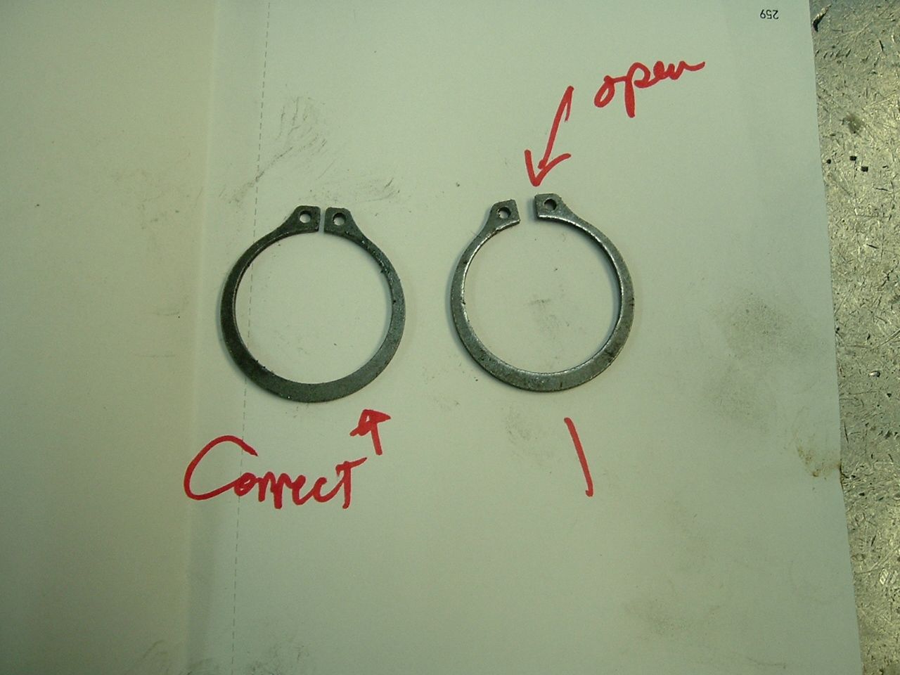
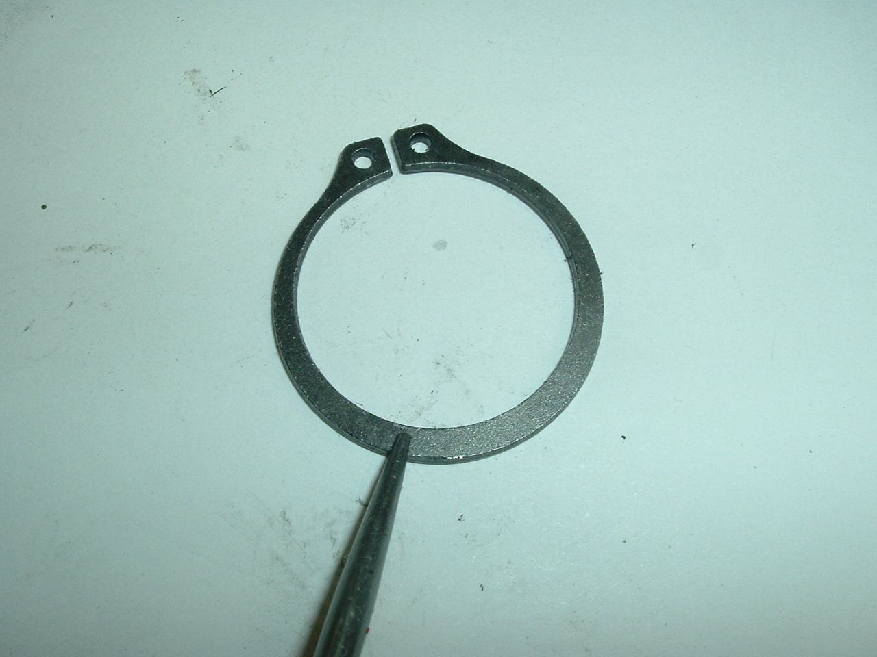
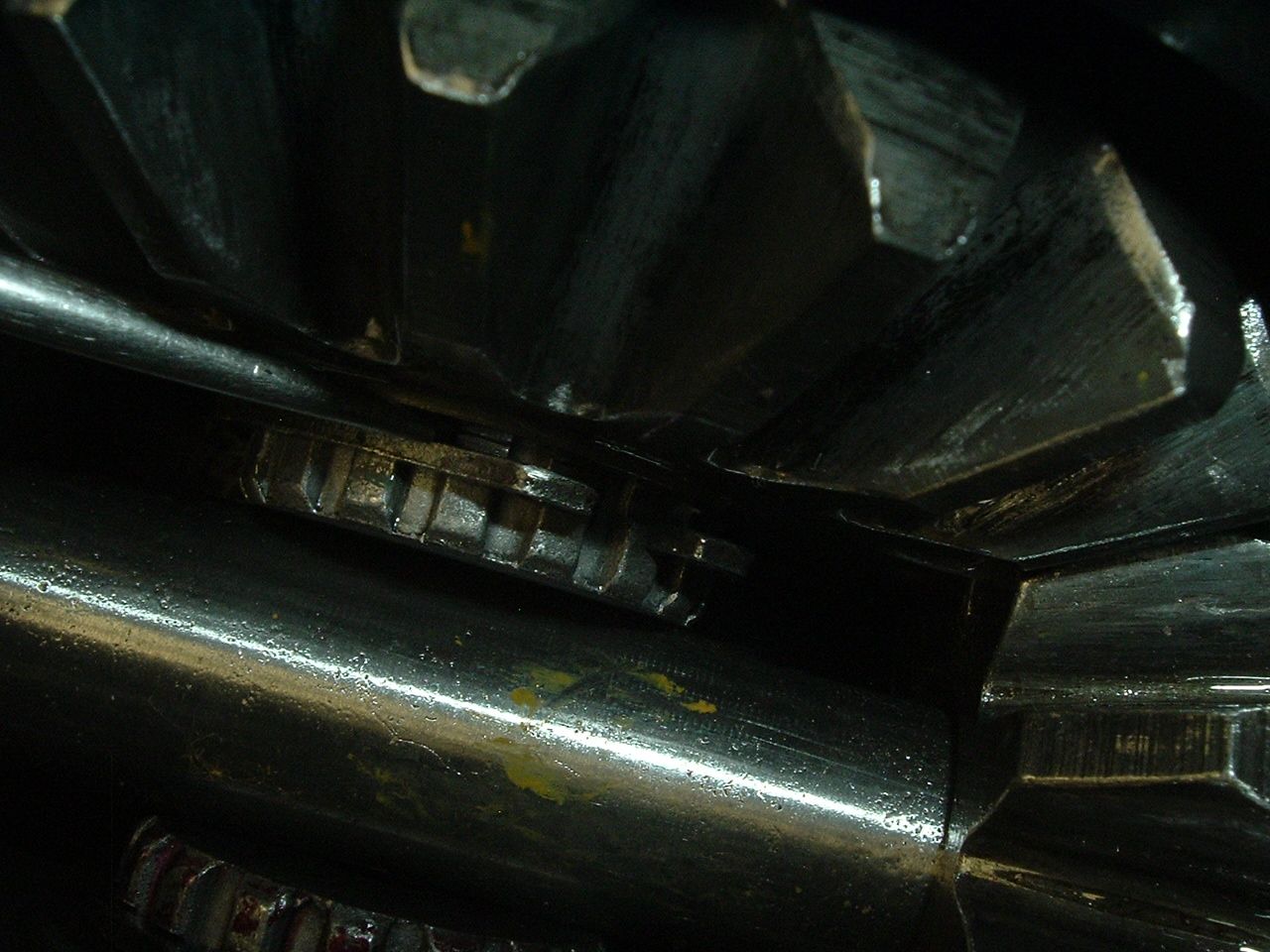
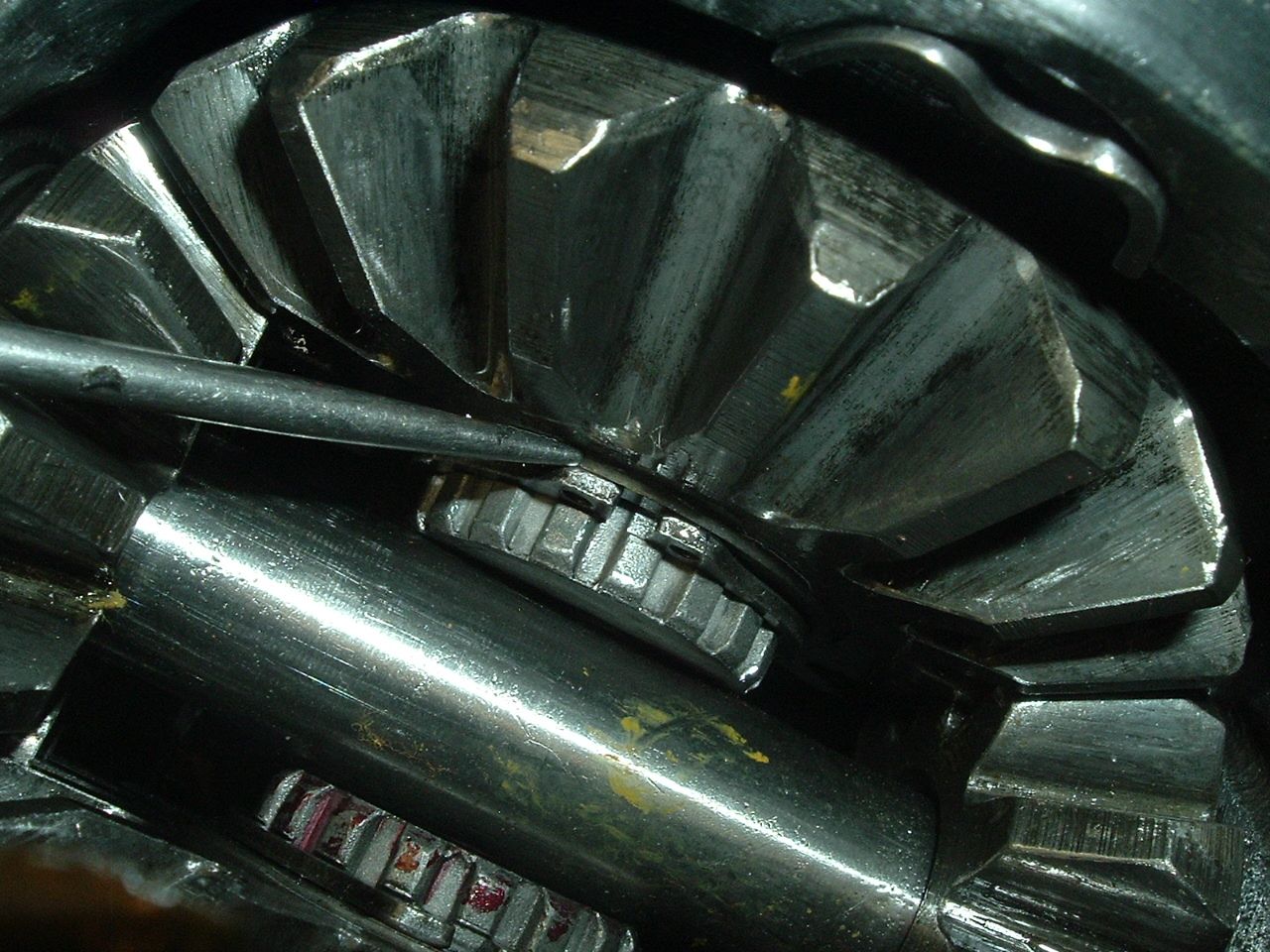
DUB, are your sure about the snap ring rounded side facing outside? The snap ring is only loaded when the stub axle is being pulled outward, therefore the retaining snap ring's rounded side should face inwards.and the flat side (load bearing side) to the outside.
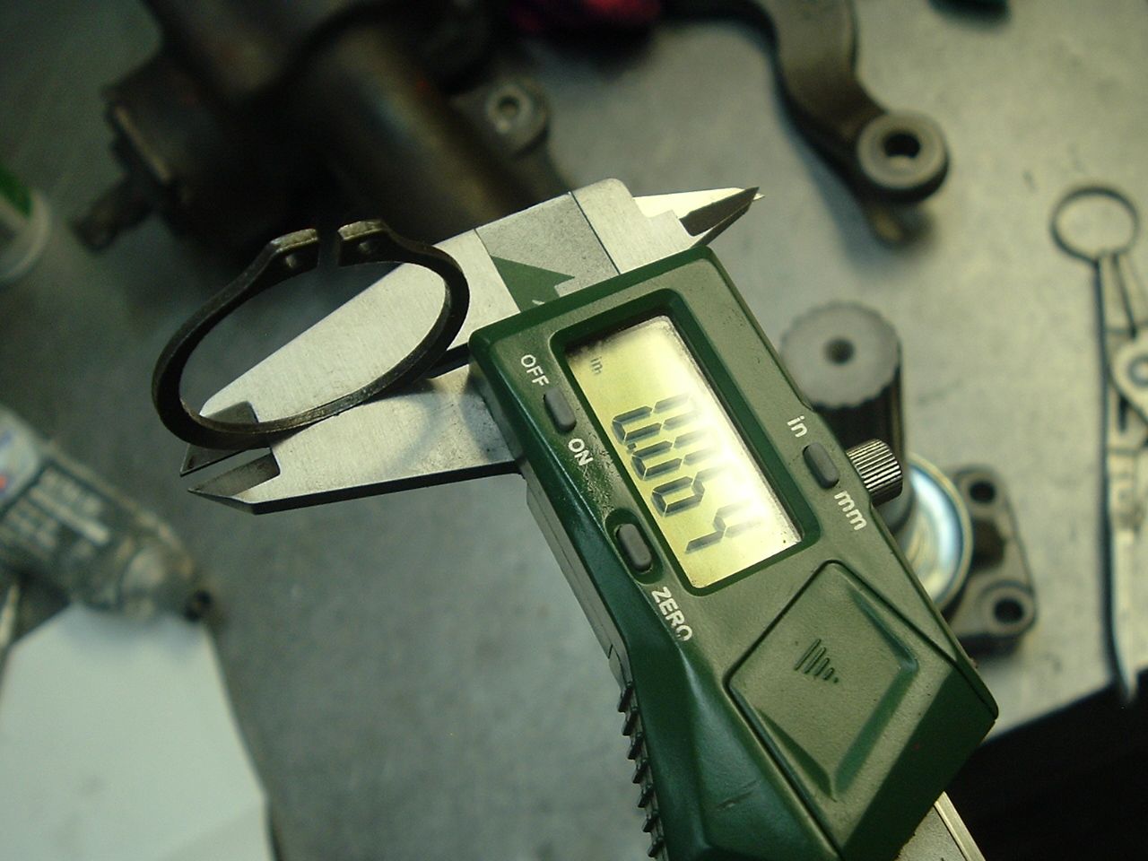
Snap ring position. I check the snap rings I got from Ecklers and fortunately there is no rounded side. They are either made in the USA or they have a bunch of little Chinese ladies with files sitting at the end of the assembly line sharpening the edges of the rings. Either way, looks like these will work.
DUB, are your sure about the snap ring rounded side facing outside? The snap ring is only loaded when the stub axle is being pulled outward, therefore the retaining snap ring's rounded side should face inwards.and the flat side (load bearing side) to the outside.
The snap ring is not doing anything when the side yoke is contacting the pinion shaft when it is on the ground.
SO the snap ring is not touching anything but the groove of the side yoke it is installed on. When the car is raised up or unloaded when driving and the side yoke begins to come out of the differential....the snap ring stops the side yoke from coming out.,
SO that means the force is beign applied on the snap ring...which means that the outer edge of the groove that is closest to the END of the side yoke which is where you want the sharp defined and NOT ROUNDED of edge of the snap ring to go so it stays locked in and can not slip out of the groove.
DUB, thanks for the detailed explanation w/drawing! Yeah, groove in the spline is the way to look at it. Super Chevy got it wrong also
Your last (edited) sentence was funny
thanks again, Greg
Now I can be wrong and Super Chevy is RIGHT...but my logic on how I see it...I have it right ...due to the guys who told me all about it explained it to me and I felt they are correct and it makes sense if you think about it.
Since then....every snap ring that has a rounded edge gets installed as how I showed it to prevent the rounded edge allowing for it to be like a ramp and allowing it to come off.
Glad that me taking the time to draw this up and explain the way I do it aided in our discussion on this.
AS always ..those of you who read this can do it as you see fit.
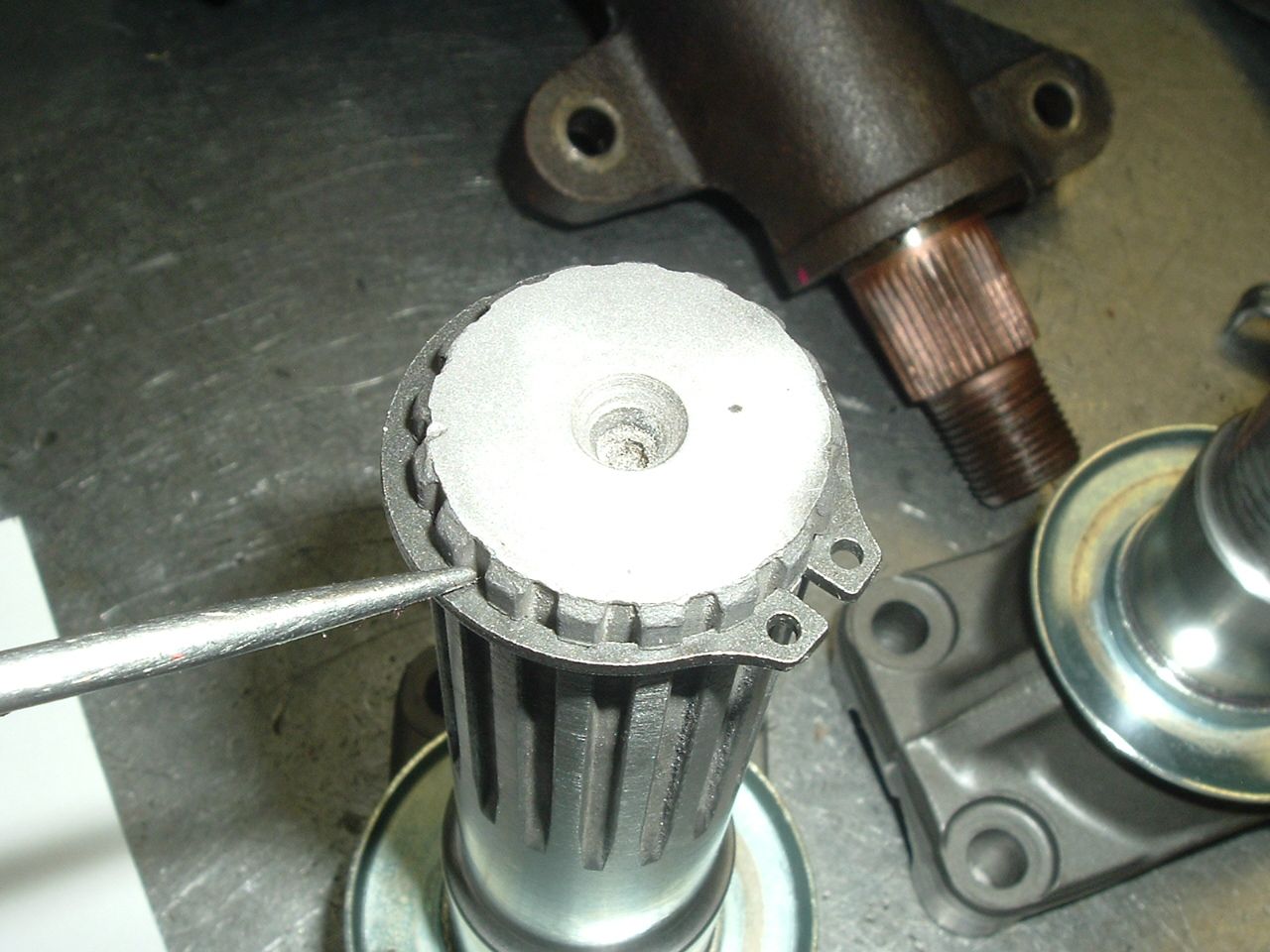
Another "Bubba" surprise on this job. Bubba had the spindle nut on finger tight with a half-destroyed cotter pin twisted in place. I'm thinking OMG one more way the thing could have come loose while driving. However, the spindle is so frozen to the bearings and shims it will not budge. I have another post asking for advice how to get the @#$%^&* thing out.
DUB, you are correct. The critical snap ring load area is on the shaft spline, easy to see when looking at your drawing.
Sorry to have spent so much of your time with this. I did make sure both of my differentials have the clips installed corrrectly, one had both clips backwards so potential disaster avoided
No need to feel sorry about the time I spent on this...Remember I can walk away and not comment on stuff like this if I choose to do so.......so it was my choice to 'pay it forward'.
'ronarndt'
I will look at your other thread due to having dealt with my fair share of REALLY SEIZED bearings before.
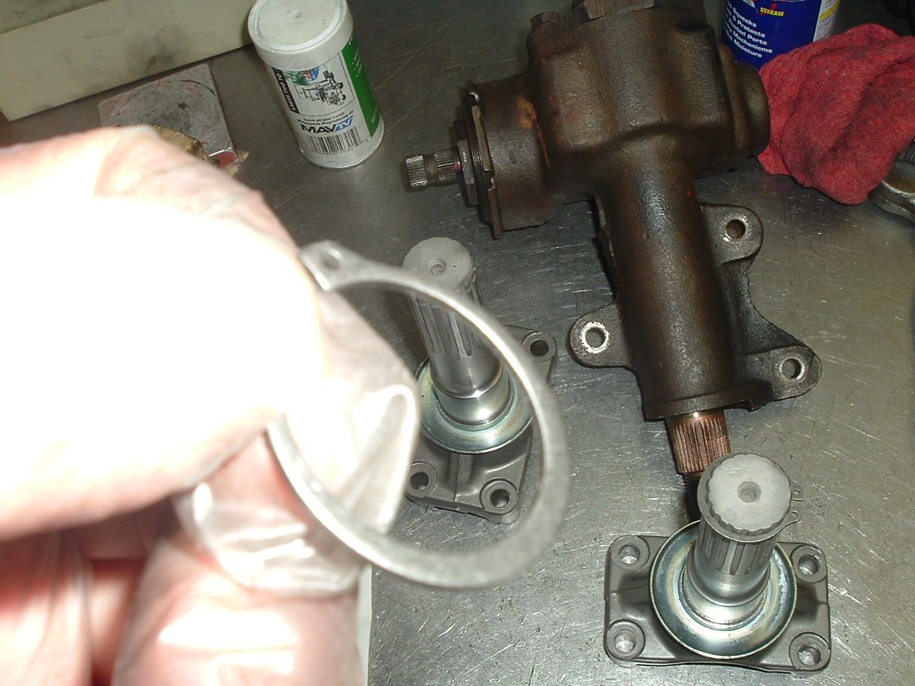
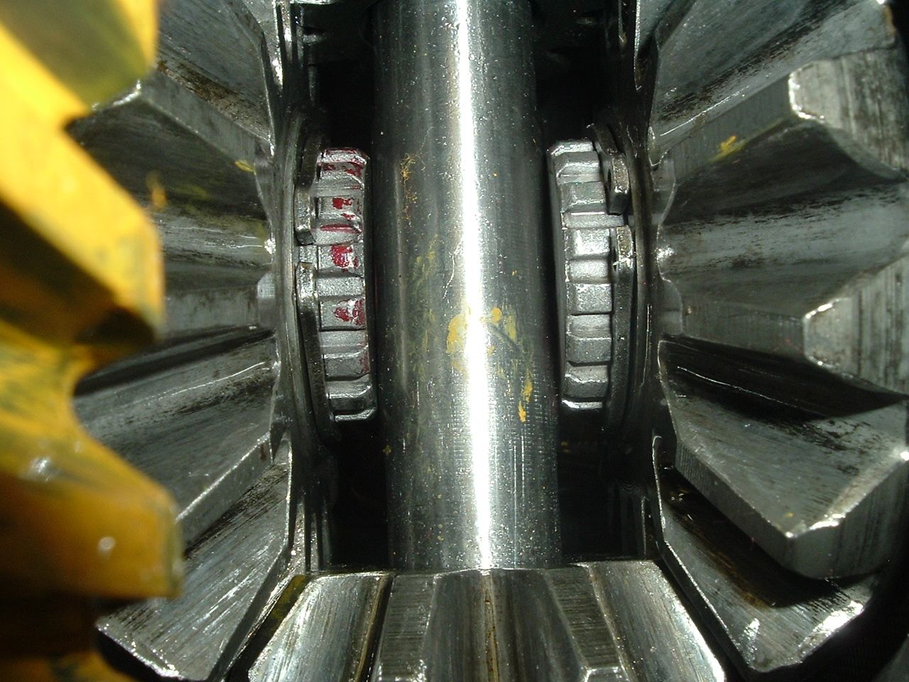
Must be something in the air... I'm refreshing mine at the moment too. This is when I pulled it apart 2 weeks ago.
Part way through polishing the posi case. Sill me, I didn't take a photo of it when completed.
I haven't taken the photos I should have... Diff is back together and in the car (raised in the chassis and now solid mounted), new offset trailing arms are in the car with refreshed handbrake assembly and wheel bearings. Just gotta chuck the second halfshaft and strut rod in, spring, brake callipers, bleed brakes, wheel alignment, and back on the road! Hoping to compete in an event on Sunday, will have to see how I go getting it back together.
After days of ripping stuff off the car, I have turned the corner and am re-installing the rear end components. All of the bushings arrived, so I was able to put the diff back in place today. I will be delayed slightly, since I sent my left side bearing assembly and spindle to Eckler's for a rebuild. Hope they have quick turn-around.

 01-28-2019, 05:53 PM