When you click on links to various merchants on this site and make a purchase, this can result in this site earning a commission. Affiliate programs and affiliations include, but are not limited to, the eBay Partner Network.
C3 Door Ajar Warning Switch Mounting Plate and Door Ajar Alarm Switch
1972 C3 Corvette Door Ajar Warning Switch Mounting Plate and Door Ajar Alarm Switch Replacement
First let me say thanks for all the knowledge I’ve gained from this forum. This is my attempt to contribute back.
During the replacement of my 1972 dash and rear harness I worked to get the factory installed alarm system working which meant replacing my faulty door ajar switches that refused to come apart/out regardless of every shop trick in the book. One side needed the switch core and rivets drilled out, the other side, the plate just fell into the lower cavity due to weak rivets backs.
After the old switches and plates were out of the way, with some paint chipping that I’ll have to address (knife scoring the perimeter of the rivets helped), the new ones needed installing. I found no way to install the switch mounting plates. On my vehicle, there was no access point that I could see on the inside, even with all the pillar trim removed. The hole accessed through the body mount cover plate, forward of the rear tires, was too small for the plate or my hand to fit through. The following is how I installed my plates and switches.
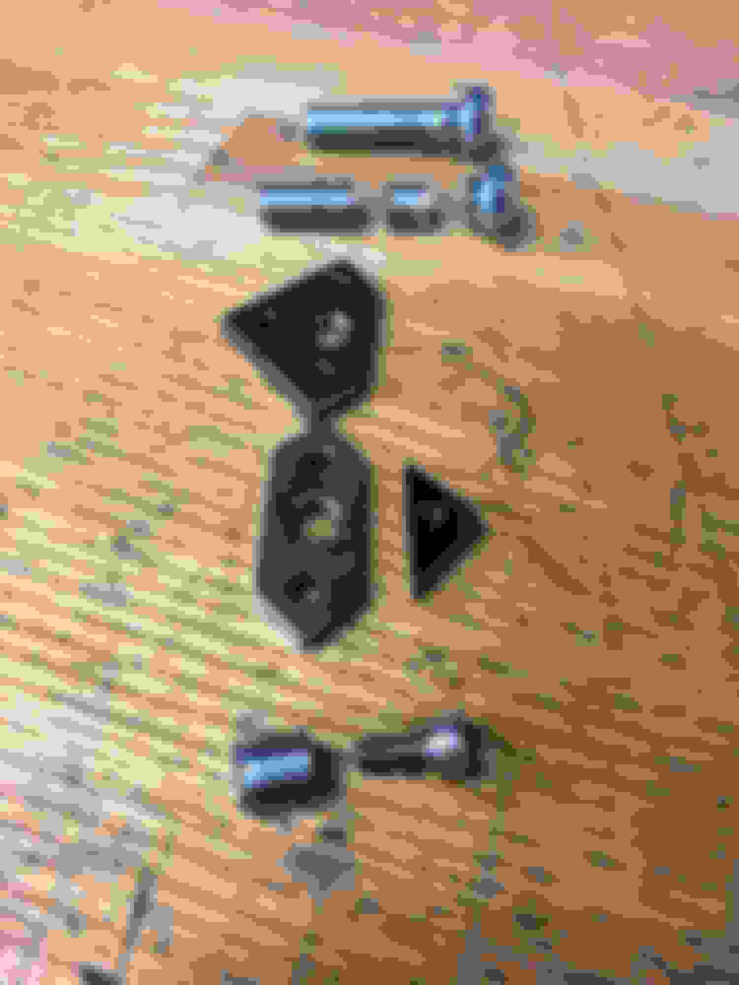
1. Modified a 3/8-24 shoulder bolt: Cut head off leaving 1/6” of the shoulder as a screw stop, center drill the core so a 3/32” wire rope will fit through, opposite the short 1/16” shoulder, cut a flat for a flat head screwdriver (I also 10-32 threaded mine but it was not needed.); call it a “bolt stub”.
2. Trim the switch mounting plate. I removed the side/corner that has a thread hole; I think some vehicles need that plate grounded so make sure you don’t need the ground before cutting that side off.
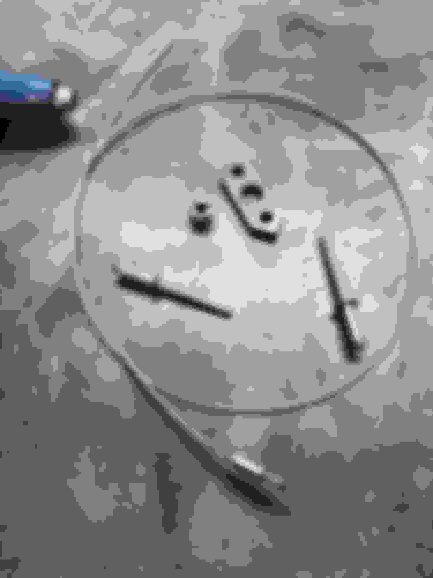
3. I used 3/32” wire rope with a crimped looped end to act as a back pull stop when seating the plate for riveting. The wire rope made it real easy to fish out the center through hole. Attach a string to the loop to retrieve the 3/8-24 bolt stub and wire rope while leaving a string to fish your connection wires.
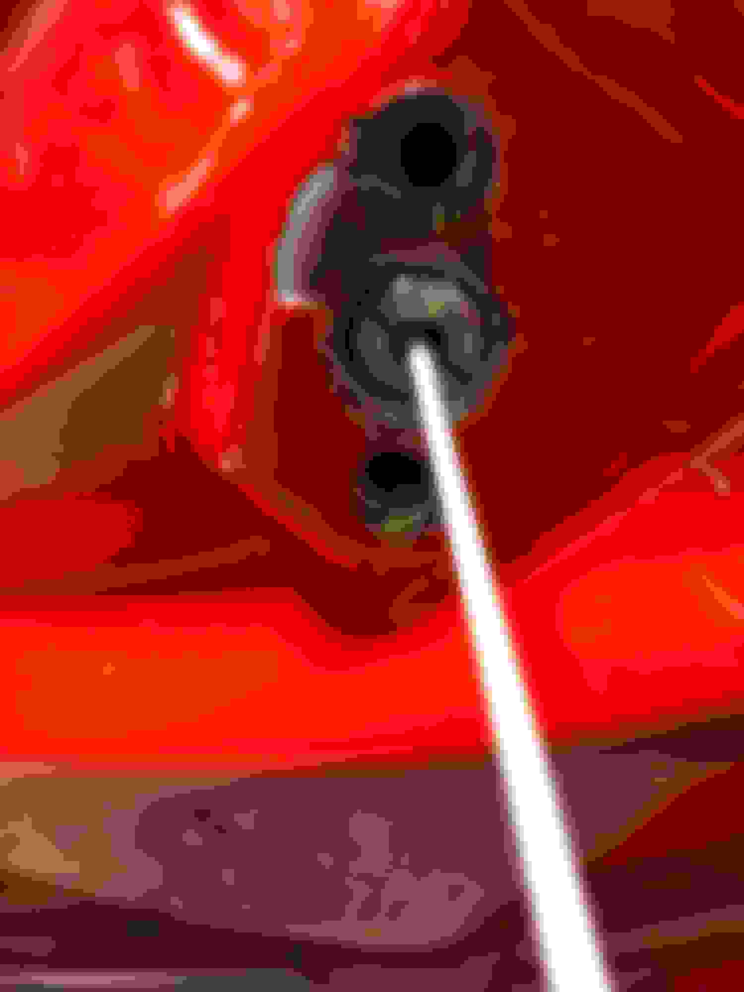
4. Assuming your access hole, accessed through the body mount cover plate forward of the rear tires, is large enough for the modified plate to fit through, fish the wire rope and switch plate through the small hole and into position. Align rivet holes and secure with two 3/16” rivets (in my case that was the previous size used). Unscrew, inward, the bolt stub and retrieve it with the wire rope. I tied the string together in loop so I would lose it during the wire fishing part. Now fish your wires to the outside, through the switch plate center hole, connect to switch and secure the switch into the switch plate… after testing the wires first for open/closed circuit. My reproduction switched wouldn’t hold the electrical pins very secure so I used a little super glue and hot glue gun to secure the wires on the backside, in the correct operating position, prior to installing the switch into the plate. Be mindful those wires and glue need to pass back through the 3/8-24 hole.
5. I added new switch bumpers to the doors. Please check your own switch clearance and travel as damage may occur when closing the door on a new switch. My bumpers were too tall. I checked the switch travel by placing a small o-ring on the plunger at the base, closed the door, opened the door and saw the o-ring traveled the whole length. I used a lower profile bumper so the switch wouldn’t bottom out.
Please remember every corvette is a little different. This worked for my vehicle and might not for yours so please evaluate prior to attempting this. I have no idea how this would affect vehicle judging… I just wanted my switches to work.
Hardware prep Hardware Hardware ready to install Fished Plate in position Wire rope and String Backing out bolt stub Pulled bolt stub and wire rope Wires fished Switch connected Final Install
For my 69 project the door button areas were kinda not there. I had the opportunity do go a little different route. You know I was going to make a mold for all of the small cures and things, anyway for those who have serious damage to that area. Just another option!
RVZIO
Nothing their! A little adhesive to hold it in place. Make a splash mold to get all the small profiles. Pop it of and size to repair area. Finished piece ready for installing Glued to area , a little VPA and sanded POP riveted and cleaned up ready to prime,

 02-22-2019, 07:27 AM